EP0160295B1 - Dispositif de liage pour presse à balles rondes - Google Patents
Dispositif de liage pour presse à balles rondes Download PDFInfo
- Publication number
- EP0160295B1 EP0160295B1 EP85105229A EP85105229A EP0160295B1 EP 0160295 B1 EP0160295 B1 EP 0160295B1 EP 85105229 A EP85105229 A EP 85105229A EP 85105229 A EP85105229 A EP 85105229A EP 0160295 B1 EP0160295 B1 EP 0160295B1
- Authority
- EP
- European Patent Office
- Prior art keywords
- twine
- cord
- guide
- guide surface
- clamping plate
- Prior art date
- Legal status (The legal status is an assumption and is not a legal conclusion. Google has not performed a legal analysis and makes no representation as to the accuracy of the status listed.)
- Expired - Lifetime
Links
- 238000004804 winding Methods 0.000 description 11
- 238000000034 method Methods 0.000 description 7
- 230000001960 triggered effect Effects 0.000 description 4
- 230000036316 preload Effects 0.000 description 1
Images


Classifications
-
- A—HUMAN NECESSITIES
- A01—AGRICULTURE; FORESTRY; ANIMAL HUSBANDRY; HUNTING; TRAPPING; FISHING
- A01F—PROCESSING OF HARVESTED PRODUCE; HAY OR STRAW PRESSES; DEVICES FOR STORING AGRICULTURAL OR HORTICULTURAL PRODUCE
- A01F15/00—Baling presses for straw, hay or the like
- A01F15/08—Details
- A01F15/14—Tying devices specially adapted for baling presses
- A01F15/141—Tying devices specially adapted for baling presses for round balers
-
- A—HUMAN NECESSITIES
- A01—AGRICULTURE; FORESTRY; ANIMAL HUSBANDRY; HUNTING; TRAPPING; FISHING
- A01F—PROCESSING OF HARVESTED PRODUCE; HAY OR STRAW PRESSES; DEVICES FOR STORING AGRICULTURAL OR HORTICULTURAL PRODUCE
- A01F15/00—Baling presses for straw, hay or the like
- A01F15/07—Rotobalers, i.e. machines for forming cylindrical bales by winding and pressing
- A01F15/071—Wrapping devices
- A01F2015/076—Wrapping device incorporating sensors
-
- A—HUMAN NECESSITIES
- A01—AGRICULTURE; FORESTRY; ANIMAL HUSBANDRY; HUNTING; TRAPPING; FISHING
- A01F—PROCESSING OF HARVESTED PRODUCE; HAY OR STRAW PRESSES; DEVICES FOR STORING AGRICULTURAL OR HORTICULTURAL PRODUCE
- A01F15/00—Baling presses for straw, hay or the like
- A01F15/08—Details
- A01F15/14—Tying devices specially adapted for baling presses
- A01F15/141—Tying devices specially adapted for baling presses for round balers
- A01F2015/143—Guiding fingers for twines in order to avoid the slippage of twines to the sides of the bale when tying it
Definitions
- the invention relates to a binding device for machines for producing cylindrical bales from crop material in a winding chamber with the features of the preamble of claim 1.
- the cord guide arm which has to be swung back and forth in front of the wrapping chamber to wrap the bale with the binding cord, usually requires a sufficiently large length to cover the entire bale width and to trigger a cord end in the area of the in when the binding process is triggered to keep the winding chamber entering crops so that the cord with the crop can be drawn into the winding chamber. Sufficient resistance must be opposed to pulling the cord into the wrapping chamber so that the finished bale can also be wrapped sufficiently tightly with the cord.
- a binding device with the features of the preamble of claim 1 is known from FR-A-2 442 579.
- a bearing block is provided on the elongated U-shaped support part for a bearing bolt running transversely to the longitudinal direction of the cord guide surface, which is arranged outside the support part and receives a pivoting part to which an L-shaped part is attached, the longer leg of which is perpendicular to the Cord guide surface extends and is connected to the pivot pin, while the shorter leg is arranged in the direction of movement of the cord in front of the pivot pin and close to the cord guide surface and parallel to it.
- a tension spring also acts on the swivel part and is attached to a spring abutment fastened to the support part at a distance from the bearing block.
- the arrangement is such that the spring action of the pivoting part is pivoted about the pivot pin in one direction, so that the shorter leg of the L-shaped part forms a tensioning plate which is held elastically against the line-guiding surface, while the cord passing underneath it strives to pivot the swivel part against the spring preload and to lift the tensioning plate from the line guide surface.
- the guide pins and the mounting device of the tensioning device are arranged within the elongated U-shaped supporting part and delimit a line guide path between them in the region of the line guide surface.
- Guide pins and tensioning device are protected in the U-shaped cross section of the support member. Since the support part is open, the parts are still easily accessible. So that the cord is guided particularly securely in the open support part. Inserting the cord in the area of the tensioning device is easy, since the cord can easily be pulled under the tensioning plate after it has been placed on the guide pins.
- the two guide pins are used not only for guiding the cord but also for freely guiding the clamping plate according to the teaching of claim 2. This further simplifies the arrangement.
- the measures of claim 4 prevent damage to the cord when passing through the tensioning device and at the same time facilitate threading the cord in the area of the tensioning device.
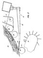
- a machine 11 for producing cylindrical bales of large dimensions from crop is shown with a binding device 12.
- the machine has two wheels 13 so that it can be pulled by a tractor by means of a trailer 15.
- the machine's equipment is driven from the PTO of the agricultural tractor.
- the winding chamber 22 is formed between two upright side walls 17 and 18 and belts or belts 14 which run over a plurality of transverse rollers 20.
- the crop is fed to the winding chamber by a pick-up 19 of conventional design.
- a tensioning device 21 monitors the density of the bale. It consists of control arms 23 and hydraulic cylinders 25 and spring devices 27. The tensioning device is tensioned accordingly as the bale diameter increases. As soon as the bale gets its target size, the binding process is triggered automatically.
- the binding device 12 comprises a cord dispensing device 30 for introducing a cord into the winding chamber 22, Drive means 32 for moving a line guide arm 34 back and forth, a control device 29 for triggering the binding cycle by sensing the increase in the bale 24, and drive means 37 for driving a hydraulic pump 38 with a control valve 39, by means of which the binding device is actuated.
- the cord 33 is severed and the finished bale can fall to the ground through the hydraulic cylinders 44 after the wrapping chamber has been opened.
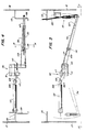
- Figures 3 to 6 show an embodiment of a binding device 30 with a cord guide arm 34.
- This consists of a tubular guide 107 for receiving the cord, and an elongated U-shaped support member 109 with a cord tensioning device 114 and a device for feeding the cord 33 to the Cord guide arm 34.
- the support part 109 has an elongated, freely accessible cord guide surface 116, along which the cord is guided from the dispensing device until it enters the tubular guide 107.
- the tubular guide 107 is considerably shorter than the support part 109, so that the threading of the cord is made considerably easier, since it is guided over the freely accessible cord guide surface 116 and only needs to be threaded through a tensioning device 114 which is arranged in the region of the cord guide surface and the cord holds on this surface. Since the tubular guide 107 is short, for example only 16 cm long, manual threading can be easily carried out without using any mechanical threading devices. Such threading devices are required in the known cord guide arms, which are tubular over their entire length. Such an auxiliary device can consist of a wire-shaped threading device.
- the tensioning device 114 is particularly simple to insert the cord 33 onto the open guide surface 116 and nevertheless provides sufficient tension for the cord 33 to prevent it from getting confused or improperly reaching the tubular guide 107.
- the tensioning device 114 comprises a plate 118 and a mounting device 122. This comprises a pin 124 and a spring 126 coaxially mounted thereon. The arrangement is such that the mounting plate 118 is tiltably mounted on the support part 109, the spring against the plate 118 biases the line guide surface 116.
- Two guide pins 128, 130 are arranged near the entry and exit sides 136, 138 of the tensioning plate 118 and, together with the pin 124, form a line path through the tensioning device 114.
- the entry side 136 has a beveled edge 136 which allows the line 33 to move freely through the Allows clamping device 114.
- the distance between the pins 128, 130 is approximately equal to the width of the tensioning plate 118 plus the diameter of the cord 33. This means that the cord 33 can be passed between the plate sides 136, 138 and the pins 128, 130, one after the other, during threading.
- An upper side 140 extends between the sides 136, 138 and also has a bevelled edge 142, which enables the cord 33 to be inserted easily under the plate 118.
- the trailing edge 138 is not beveled and lies in the plane of the tensioning plate 118, so that it engages the cord 33 and counteracts accidental threading out of the cord 33 during the movement from right to left in FIG. 4.
- the line guide arm 34 is moved in front of the winding chamber between a first position at approximately -15 ° (shown here as a fully extended position on the left side of the machine) and a second position at approximately 195 ° (shown here as a dashed position).
- the cord guide arm 34 is between the two positions moves a hydraulic cylinder 112 of the drive device 32.
- the line guide arm 34 is connected to a toothed member 110 which is mounted on the support part 109.
- the cylinder 112 is in driving engagement with the toothed member 110 through a member 103 which is pivotally hinged at one end to the piston rod 108 of the cylinder 112 and is attached at its other end to a driven gear 117.
- the latter is rotatably mounted on the support part 112 of the line guide arm in the middle between the side walls 17 and 18 and is in direct engagement with the toothed member 110.
- Cord guides 113 and 115 are each mounted on the side walls 18, 17 to limit the path of the cord 33 into the winding chamber. This prevents the cord 33 from moving closer to the side walls 18, 17 than the vertical legs 118, 119 of the guides allow. This results in additional windings at the end of the bale, in connection with the large swivel range of the line guide arm 34 between the positions at -15 ° and + 195 °.
- the cord guide arm 34 is initially on the left side wall 18.
- a binding cycle is triggered, namely by the control device 29, which scans the desired diameter of the bale
- a valve 39 is adjusted in order to activate the pump drive 37.
- the pump 38 feeds the cylinder 112 and the piston 108 is extended.
- the cord guide arm is pivoted from its first position on the left to its second position on the right.
- the arm 34 reaches the middle between the side walls, the free end of the cord 33 is gripped by the incoming crop and pulled into the bale wrapping chamber, whereby the binding process is triggered.
- the tying process starts in the middle of the bale, additional wraps will be applied at each end of the bale.
- the twine guide arm engages the actuating arm 101 to release the latch 95 when the piston rod 108 is fully extended.
- a valve control arm 89 is then moved from position B to position C under the bias of spring 91. This changes the position of the valve so that hydraulic cylinder 112 is retracted to return the line guide arm to its original position.
- the line guide arm 34 engages a line separator 35 to sever the line.
- the cord 33 is threaded through the tensioning device 114 by first inserting it between the bevelled edge 142 and the cord guide surface 116. Thereafter, the cord portion near the entry side 136 of the tension plate 118 is pulled out and down, causing the tension plate 118 to pivot clockwise. This allows the cord to pass between edge 136 and pin 128 and lies between pin 128 and pin 124. The cord is then pulled outward and downward near the trailing edge 138 to pivot the tension plate 118 counterclockwise so that the cord is between the Edge 138 and pin 130 can pass through and come to rest between pin 124 and pin 130. The threading process is ended by pushing the cord through the short tubular end piece 107 of the guide.
- tensioning device can also be used in connection with other line guide arms.
- FIG. 7 shows the parts of the hydraulic drive device 32 for moving the line guide arm 34 back and forth.
- the double-acting cylinder 112, the hydraulic pump 38, and a four-way / two-position slide valve 34 connecting the two parts are shown.
- a flow control valve device is shown at 211. This is designed so that the inflow through line 215 to the connection 217 of the cylinder 112 is free, ie uncontrolled, while the outflow through the line and via a filter 221 to the sump 219 takes place under precise flow control.
- Figure 7 shows the hydraulic circuit in a position between two binding operations.
- the control arm 89 for the valve is in position A.
- the pump 38 is not driven.
- the pump When the control device 29 triggers a pivoting of the control arm 89 from the position A to the position B, the pump is activated and the valve 39 is switched from the position shown, so that the pump 38 can feed the cylinder 112 freely via the connection 217 while the connection 223 the pressure medium flows back through filters to the sump.
- the piston 115 with the piston rod 108 are extended and the cord guide arm is pivoted.
- the valve 39 When the control arm 89 is moved from the B position to the C position, the valve 39 is reset and the pressure medium is supplied to the connection 223, while the discharge via the line 215 takes place under precise flow control.
- the piston 115 and the piston rod 108 retract and the line guide arm is pivoted back. At the end of the stroke, the cord 33 is cut by the cutting device 35. Then the bale is ejected.
- the control device 29 switches the pump off and moves the control arm 89 from position C to position A without the valve 39 its position is changed. The arrangement is ready for the next binding process.
Landscapes
- Life Sciences & Earth Sciences (AREA)
- Environmental Sciences (AREA)
- Basic Packing Technique (AREA)
- Storage Of Harvested Produce (AREA)
- Preliminary Treatment Of Fibers (AREA)
Claims (4)
- Dispositif de liage installé dans des machines servant à former des balles cylindriques d'une récolte dans une chambre d'enveloppement, comportant un bras guide-ficelle (34) déplaçable en va-et-vient devant la chambre d'enveloppement et qui est soutenu, de manière à pouvoir pivoter, à l'une de ses extrémités et comporte, au niveau d'une partie de support allongée en forme de U (109), une surface allongée (116) de guidage de la ficelle, librement accessible, et, au niveau de son extrémité libre, un guideficelle fermé (107), qui possède un passage central pour la ficelle et dont la longueur est nettement inférieure à celle de la surface (116) de guidage de la ficelle et dans lequel il est prévu un dispositif de serrage (114), qui retient le fil (33) sur la surface (116) de guidage de la ficelle, comporte une plaque de serrage (118) et peut être repoussé, au moyen d'un dispositif de précontrainte (126), contre la surface de guidage (116), caractérisé en ce que des broches de guidage (128,130) sont disposées à une certaine distance l'une de l'autre à l'entrée (136) et à la sortie (138) du dispositif de serrage (114) et qu'une voie de guidage de la ficelle est délimitée entre les broches de guidage d'un côté et un dispositif de montage (122) du dispositif de serrage de l'autre côté.
- Dispositif de liage selon la revendication 1, caractérisé en ce que la plaque de serrage (118) s'étend entre les deux tiges de guidage (128,130), qui sont disposées respectivement à proximité de l'entrée (136) de la ficelle et de la sortie (138) de la ficelle de la plaque de serrage (118).
- Dispositif de liage selon la revendication 1 ou 2, caractérisé en ce que le dispositif de montage (122) comporte, pour la fixation de la plaque de serrage (118) sur la surface de guidage (116), une tige (14) insérée dans une ouverture de la partie supérieure (106) et un ressort (126) emmanché sur la tige et servant à maintenir, avec possibilité de basculement, la plaque de serrage (118) entre les tiges de guidage (128,130).
- Dispositif de liage selon la revendication 2 ou 3, caractérisé en ce que côté entrée (136), le bord d'entrée de la plaque de serrage (118) forme un biseau s'écartant de la surface (116) de guidage de la ficelle et possède une troisième face (142) qui est parallèle à la direction de passage de la ficelle et possède un bord (140) comportant un biseau s'écartant de la surface de guidage.
Applications Claiming Priority (2)
| Application Number | Priority Date | Filing Date | Title |
|---|---|---|---|
| US303274 | 1981-09-17 | ||
| US06/303,274 US4457226A (en) | 1981-09-17 | 1981-09-17 | Twine-wrapping mechanism for a large round baler |
Related Parent Applications (1)
| Application Number | Title | Priority Date | Filing Date |
|---|---|---|---|
| EP82108465.4 Division | 1982-09-14 |
Publications (3)
| Publication Number | Publication Date |
|---|---|
| EP0160295A2 EP0160295A2 (fr) | 1985-11-06 |
| EP0160295A3 EP0160295A3 (en) | 1989-01-04 |
| EP0160295B1 true EP0160295B1 (fr) | 1991-06-05 |
Family
ID=23171306
Family Applications (5)
| Application Number | Title | Priority Date | Filing Date |
|---|---|---|---|
| EP82108465A Expired EP0075252B1 (fr) | 1981-09-17 | 1982-09-14 | Dispositif de liage automatique pour une machine à former des balles de fourrage cylindriques |
| EP85105228A Expired - Lifetime EP0159048B1 (fr) | 1981-09-17 | 1982-09-14 | Dispositif de liage automatique pour balles cylindriques dans une chambre d'enroulage |
| EP85105229A Expired - Lifetime EP0160295B1 (fr) | 1981-09-17 | 1982-09-14 | Dispositif de liage pour presse à balles rondes |
| EP85105230A Expired - Lifetime EP0159049B1 (fr) | 1981-09-17 | 1982-09-14 | Dispositif de liage pour balles cylindriques |
| EP85105231A Expired EP0156400B1 (fr) | 1981-09-17 | 1982-09-14 | Dispositif de liage pour balles cylindriques |
Family Applications Before (2)
| Application Number | Title | Priority Date | Filing Date |
|---|---|---|---|
| EP82108465A Expired EP0075252B1 (fr) | 1981-09-17 | 1982-09-14 | Dispositif de liage automatique pour une machine à former des balles de fourrage cylindriques |
| EP85105228A Expired - Lifetime EP0159048B1 (fr) | 1981-09-17 | 1982-09-14 | Dispositif de liage automatique pour balles cylindriques dans une chambre d'enroulage |
Family Applications After (2)
| Application Number | Title | Priority Date | Filing Date |
|---|---|---|---|
| EP85105230A Expired - Lifetime EP0159049B1 (fr) | 1981-09-17 | 1982-09-14 | Dispositif de liage pour balles cylindriques |
| EP85105231A Expired EP0156400B1 (fr) | 1981-09-17 | 1982-09-14 | Dispositif de liage pour balles cylindriques |
Country Status (6)
| Country | Link |
|---|---|
| US (1) | US4457226A (fr) |
| EP (5) | EP0075252B1 (fr) |
| AU (4) | AU559134B2 (fr) |
| CA (1) | CA1202817A (fr) |
| DE (4) | DE3280342D1 (fr) |
| ES (1) | ES515757A0 (fr) |
Families Citing this family (28)
| Publication number | Priority date | Publication date | Assignee | Title |
|---|---|---|---|---|
| US4437399A (en) | 1982-05-28 | 1984-03-20 | Deere & Company | Twine-wrapping mechanism for mechanism for a large round baler |
| NL8304136A (nl) * | 1983-12-01 | 1985-07-01 | Texas Industries Inc | Inrichting voor het vormen van balen gewas. |
| DE3772409D1 (de) * | 1986-03-05 | 1991-10-02 | Deere & Co | Maschine zur bildung von rundballen. |
| US4677807A (en) * | 1986-07-08 | 1987-07-07 | Deere & Company | System for automatically enveloping a large round bale with a wrapping |
| FR2604857B1 (fr) * | 1986-10-10 | 1989-01-06 | Rivierre Casalis | Procede et dispositif de commande de bras de guidage de ficelle de liage de balles cylindriques dans une presse ramasseuse |
| US4800811A (en) * | 1987-06-01 | 1989-01-31 | Deere & Company | Dwell-effecting twine arm drive link |
| US4793249A (en) * | 1987-06-01 | 1988-12-27 | Deere & Company | Double twine arm for dispensing twine into a bale chamber |
| GB2210322B (en) * | 1987-09-30 | 1991-05-01 | Deere & Co | Machine for forming cylindrical bales of crop |
| US5215006A (en) * | 1992-03-09 | 1993-06-01 | Ford New Holland, Inc. | Twine clamp for round baler twine wrapping apparatus |
| US5437226A (en) * | 1994-05-02 | 1995-08-01 | New Holland North America, Inc. | Twine cutter for a round baler |
| US5450787A (en) * | 1995-01-12 | 1995-09-19 | New Holland North America, Inc. | Twine clamp for round baler twine wrapping apparatus |
| US5709143A (en) * | 1995-11-21 | 1998-01-20 | Hay & Forage Industries | Round baler twine cutter |
| US6209450B1 (en) * | 1998-08-03 | 2001-04-03 | New Holland North America, Inc. | Round baler with improved twine wrap control |
| US6016646A (en) * | 1998-08-26 | 2000-01-25 | Deere & Company | Adjustable, resilent twine guide finger for twine wrap mechanism of large round baler |
| US6035773A (en) * | 1998-11-03 | 2000-03-14 | Vermeer Manufacturing Company | Method of controlling application of twine to a bale in an agricultural baler |
| DE10121831A1 (de) * | 2001-05-04 | 2002-11-07 | Lely Maschinenfabrik Gmbh | Rundballenpresse für Abfallmaterialien |
| DE10333592B4 (de) * | 2003-07-24 | 2012-08-02 | Deere & Company | Bindearm einer Bindevorrichtung |
| DE102004033436A1 (de) * | 2004-07-10 | 2006-02-16 | Deere & Company, Moline | Vorrichtung zum Sichern eines losen Garnendes auf einem Rundballen |
| US7337713B1 (en) * | 2006-08-01 | 2008-03-04 | Agco Corporation | Bale wrapping pattern controller and method |
| US20100077716A1 (en) * | 2008-09-26 | 2010-04-01 | Sonne Randy D | Baler with hydraulic clutch |
| US8333146B2 (en) * | 2010-03-29 | 2012-12-18 | Cnh America Llc | Twine end wrap adjustment for agricultural baler |
| DE102010003878A1 (de) | 2010-04-12 | 2011-10-13 | Alexander Moreno-Stolz | Bandverbindungs-und Austauschsystem |
| US9185847B2 (en) * | 2013-05-03 | 2015-11-17 | Deere & Company | Binding apparatus |
| US10736272B2 (en) * | 2018-03-09 | 2020-08-11 | Deere & Company | Material wrap system with automatic drive tension compensation |
| CN109775006B (zh) * | 2019-01-19 | 2024-07-02 | 中山天威龙自动化科技有限公司 | 一种捆绑机 |
| CN113057027A (zh) * | 2021-03-31 | 2021-07-02 | 中国农业科学院兰州畜牧与兽药研究所 | 一种高效的畜牧牧草打捆绑扎装置 |
| CN115413520B (zh) * | 2022-08-24 | 2023-08-29 | 桂林电子科技大学 | 一种可实现草绳螺旋升降缠绕树干的装置 |
| CN115562070B (zh) * | 2022-10-11 | 2025-03-11 | 郑州捷安高科股份有限公司 | 一种液压杆的仿真控制方法、装置、设备及存储介质 |
Family Cites Families (16)
| Publication number | Priority date | Publication date | Assignee | Title |
|---|---|---|---|---|
| US2468641A (en) * | 1944-03-03 | 1949-04-26 | Allis Chalmers Mfg Co | Rotary baler |
| US2667729A (en) * | 1949-07-30 | 1954-02-02 | Allis Chalmers Mfg Co | Control mechanism for rotary balers |
| US3913473A (en) * | 1974-07-17 | 1975-10-21 | Deere & Co | Bale wrapping mechanism for large cylindrical bales |
| US3894484A (en) * | 1974-07-17 | 1975-07-15 | Deere & Co | Bale wrapping mechanism for large cylindrical bales |
| US4024804A (en) * | 1975-11-17 | 1977-05-24 | Gehl Company | Rotary baling machine with twine feeding mechanism and articulated drive assembly |
| US4009559A (en) * | 1976-02-09 | 1977-03-01 | Sperry Rand Corporation | Synchronizing roll forming and wrapping operations in a crop material roll forming machine |
| US4057954A (en) * | 1976-02-09 | 1977-11-15 | Sperry Rand Corporation | Material layer diverting means for a crop material roll forming machine |
| US4062279A (en) * | 1976-08-30 | 1977-12-13 | Sperry Rand Corporation | Twine wrapping mechanism for a roll forming machine |
| US4072095A (en) * | 1976-08-30 | 1978-02-07 | Sperry Rand Corporation | Twine wrapping mechanism for a roll forming machine |
| DE2801309A1 (de) * | 1978-01-13 | 1979-07-19 | Claas Maschf Gmbh Geb | Verfahren und vorrichtung zum binden von rundballen aus landwirtschaftlichem erntegut |
| US4150614A (en) * | 1978-02-21 | 1979-04-24 | Schwartz Dale R | Automatic round bale wrapping assembly |
| US4158331A (en) * | 1978-04-07 | 1979-06-19 | Sperry Rand Corporation | Center pivot dispensing apparatus |
| US4167844A (en) * | 1978-04-07 | 1979-09-18 | Sperry Rand Corporation | Automatic twine wrapping apparatus |
| DE2947442A1 (de) * | 1978-11-28 | 1980-07-17 | Sperry Nv | Maschine zum formen von rundballen aus erntegut |
| US4253387A (en) * | 1979-07-03 | 1981-03-03 | Hesston Corporation | Twine actuated cutter in a rotary crop baler |
| FR2488770A1 (fr) * | 1980-08-20 | 1982-02-26 | Deere John Cie Francaise | Dispositif de liage pour presses a balles cylindriques |
-
1981
- 1981-09-17 US US06/303,274 patent/US4457226A/en not_active Expired - Lifetime
-
1982
- 1982-08-25 AU AU87585/82A patent/AU559134B2/en not_active Ceased
- 1982-08-26 CA CA000410203A patent/CA1202817A/fr not_active Expired
- 1982-09-14 DE DE8585105229T patent/DE3280342D1/de not_active Expired - Lifetime
- 1982-09-14 EP EP82108465A patent/EP0075252B1/fr not_active Expired
- 1982-09-14 EP EP85105228A patent/EP0159048B1/fr not_active Expired - Lifetime
- 1982-09-14 EP EP85105229A patent/EP0160295B1/fr not_active Expired - Lifetime
- 1982-09-14 DE DE8585105230T patent/DE3280385D1/de not_active Expired - Lifetime
- 1982-09-14 DE DE8585105228T patent/DE3280341D1/de not_active Expired - Lifetime
- 1982-09-14 DE DE8282108465T patent/DE3276044D1/de not_active Expired
- 1982-09-14 EP EP85105230A patent/EP0159049B1/fr not_active Expired - Lifetime
- 1982-09-14 EP EP85105231A patent/EP0156400B1/fr not_active Expired
- 1982-09-16 ES ES515757A patent/ES515757A0/es active Granted
-
1987
- 1987-01-19 AU AU67676/87A patent/AU6767687A/en not_active Abandoned
- 1987-01-19 AU AU67677/87A patent/AU574002B2/en not_active Withdrawn - After Issue
- 1987-01-19 AU AU67678/87A patent/AU573468B2/en not_active Expired - Fee Related
Also Published As
| Publication number | Publication date |
|---|---|
| EP0156400B1 (fr) | 1988-11-30 |
| EP0159048B1 (fr) | 1991-06-05 |
| EP0159048A2 (fr) | 1985-10-23 |
| AU559134B2 (en) | 1987-02-26 |
| EP0159048A3 (en) | 1989-01-04 |
| DE3276044D1 (en) | 1987-05-21 |
| DE3280341D1 (de) | 1991-07-11 |
| ES8308198A1 (es) | 1983-08-16 |
| EP0159049B1 (fr) | 1992-01-02 |
| EP0160295A3 (en) | 1989-01-04 |
| EP0159049A3 (en) | 1989-01-18 |
| EP0159049A2 (fr) | 1985-10-23 |
| EP0160295A2 (fr) | 1985-11-06 |
| ES515757A0 (es) | 1983-08-16 |
| AU6767887A (en) | 1987-04-30 |
| CA1202817A (fr) | 1986-04-08 |
| AU6767787A (en) | 1987-04-30 |
| US4457226A (en) | 1984-07-03 |
| DE3280342D1 (de) | 1991-07-11 |
| EP0156400A2 (fr) | 1985-10-02 |
| AU574002B2 (en) | 1988-06-23 |
| EP0075252A2 (fr) | 1983-03-30 |
| AU6767687A (en) | 1987-04-30 |
| AU573468B2 (en) | 1988-06-09 |
| EP0075252B1 (fr) | 1987-04-15 |
| EP0075252A3 (en) | 1984-10-17 |
| AU8758582A (en) | 1983-03-24 |
| EP0156400A3 (en) | 1986-01-08 |
| DE3280385D1 (de) | 1992-02-13 |
Similar Documents
| Publication | Publication Date | Title |
|---|---|---|
| EP0160295A2 (fr) | Dispositif de liage pour presse à balles rondes | |
| DE2851035C2 (de) | Erntegut-Rundballenformmaschine | |
| DE69102990T2 (de) | Anbringervorrichtung für umhüllnetz in eine rundballenpresse. | |
| DE2645762C3 (de) | Vorrichtung zum Umschnüren eines Rollballens aus landwirtschaftlichem Halmgut | |
| DE3150614C2 (de) | Automatische Umschnürungsvorrichtung an landwirtschaftlichen Rollballenpressen | |
| DE2801309C2 (fr) | ||
| DE3418681A1 (de) | Rollballenpresse fuer landwirtschaftliche halmgueter mit einer huellvorrichtung | |
| DE69015338T2 (de) | Ballenumwickelvorrichtung für Rundballenpressen. | |
| EP2225948A2 (fr) | Dispositif d'entrée pour éléments de suspension | |
| DE2947388C2 (fr) | ||
| DE3617155C2 (fr) | ||
| DE2530320C3 (de) | Bindevorrichtung für Wickelballenpressen | |
| EP0197952A1 (fr) | Procede et dispositif pour la confection de bottes a partir de vegetaux coupes | |
| EP0095689B1 (fr) | Presse à balles rondes dont la chambre de compactage comprend une entrée pour le matériau | |
| DE3024101A1 (de) | Bindegarnbetaetigter abschneider fuer eine rollballen-formvorrichtung | |
| DE2620807A1 (de) | Vorrichtung zum umschnueren eines rollballens aus landwirtschaftlichem halmgut | |
| DE10153517A1 (de) | Bindevorrichtung für eine Rundballenpresse | |
| DE3002988C2 (fr) | ||
| DE3330757A1 (de) | Grossballenpresse fuer landwirtschaftliches erntegut | |
| DE3633428C2 (de) | Vorrichtung zum Durchtrennen eines Faserbandes bei einer Spinnereivorbereitungsmaschine, insbesondere einer Strecke | |
| EP0095681B1 (fr) | Presse à balles rondes | |
| EP0464651B1 (fr) | Presse pour grandes balles | |
| DE3344992A1 (de) | Rundballenpresse | |
| EP1099367B1 (fr) | Dispositif d'alimentation de gaine pour enrubannage | |
| DE2525491A1 (de) | Rollballenpresse fuer landwirtschaftliche halmgueter mit einer bindegarn- abschneidevorrichtung |
Legal Events
| Date | Code | Title | Description |
|---|---|---|---|
| PUAI | Public reference made under article 153(3) epc to a published international application that has entered the european phase |
Free format text: ORIGINAL CODE: 0009012 |
|
| AC | Divisional application: reference to earlier application |
Ref document number: 75252 Country of ref document: EP |
|
| AK | Designated contracting states |
Designated state(s): BE DE FR GB IT LU NL |
|
| 17P | Request for examination filed |
Effective date: 19851029 |
|
| PUAL | Search report despatched |
Free format text: ORIGINAL CODE: 0009013 |
|
| AK | Designated contracting states |
Kind code of ref document: A3 Designated state(s): BE DE FR GB IT LU NL |
|
| 17Q | First examination report despatched |
Effective date: 19891213 |
|
| GRAA | (expected) grant |
Free format text: ORIGINAL CODE: 0009210 |
|
| AC | Divisional application: reference to earlier application |
Ref document number: 75252 Country of ref document: EP |
|
| AK | Designated contracting states |
Kind code of ref document: B1 Designated state(s): BE DE FR GB IT LU NL |
|
| GBT | Gb: translation of ep patent filed (gb section 77(6)(a)/1977) | ||
| ITF | It: translation for a ep patent filed | ||
| REF | Corresponds to: |
Ref document number: 3280342 Country of ref document: DE Date of ref document: 19910711 |
|
| ET | Fr: translation filed | ||
| PLBE | No opposition filed within time limit |
Free format text: ORIGINAL CODE: 0009261 |
|
| STAA | Information on the status of an ep patent application or granted ep patent |
Free format text: STATUS: NO OPPOSITION FILED WITHIN TIME LIMIT |
|
| 26N | No opposition filed | ||
| PGFP | Annual fee paid to national office [announced via postgrant information from national office to epo] |
Ref country code: LU Payment date: 19920826 Year of fee payment: 11 |
|
| PGFP | Annual fee paid to national office [announced via postgrant information from national office to epo] |
Ref country code: BE Payment date: 19920923 Year of fee payment: 11 |
|
| PGFP | Annual fee paid to national office [announced via postgrant information from national office to epo] |
Ref country code: NL Payment date: 19920930 Year of fee payment: 11 |
|
| EPTA | Lu: last paid annual fee | ||
| PG25 | Lapsed in a contracting state [announced via postgrant information from national office to epo] |
Ref country code: LU Free format text: LAPSE BECAUSE OF NON-PAYMENT OF DUE FEES Effective date: 19930914 |
|
| PG25 | Lapsed in a contracting state [announced via postgrant information from national office to epo] |
Ref country code: BE Effective date: 19930930 |
|
| BERE | Be: lapsed |
Owner name: DEERE & CY Effective date: 19930930 |
|
| PG25 | Lapsed in a contracting state [announced via postgrant information from national office to epo] |
Ref country code: NL Effective date: 19940401 |
|
| NLV4 | Nl: lapsed or anulled due to non-payment of the annual fee | ||
| PGFP | Annual fee paid to national office [announced via postgrant information from national office to epo] |
Ref country code: GB Payment date: 19940726 Year of fee payment: 13 |
|
| PGFP | Annual fee paid to national office [announced via postgrant information from national office to epo] |
Ref country code: FR Payment date: 19940914 Year of fee payment: 13 |
|
| PGFP | Annual fee paid to national office [announced via postgrant information from national office to epo] |
Ref country code: DE Payment date: 19941122 Year of fee payment: 13 |
|
| PG25 | Lapsed in a contracting state [announced via postgrant information from national office to epo] |
Ref country code: GB Effective date: 19950914 |
|
| GBPC | Gb: european patent ceased through non-payment of renewal fee |
Effective date: 19950914 |
|
| PG25 | Lapsed in a contracting state [announced via postgrant information from national office to epo] |
Ref country code: FR Effective date: 19960531 |
|
| PG25 | Lapsed in a contracting state [announced via postgrant information from national office to epo] |
Ref country code: DE Effective date: 19960601 |
|
| REG | Reference to a national code |
Ref country code: FR Ref legal event code: ST |