EP0160319A2 - Kreuzgelenk - Google Patents
Kreuzgelenk Download PDFInfo
- Publication number
- EP0160319A2 EP0160319A2 EP85105386A EP85105386A EP0160319A2 EP 0160319 A2 EP0160319 A2 EP 0160319A2 EP 85105386 A EP85105386 A EP 85105386A EP 85105386 A EP85105386 A EP 85105386A EP 0160319 A2 EP0160319 A2 EP 0160319A2
- Authority
- EP
- European Patent Office
- Prior art keywords
- connecting piece
- pivot shaft
- universal joint
- pivot shafts
- pivot
- Prior art date
- Legal status (The legal status is an assumption and is not a legal conclusion. Google has not performed a legal analysis and makes no representation as to the accuracy of the status listed.)
- Withdrawn
Links
Images


Classifications
-
- F—MECHANICAL ENGINEERING; LIGHTING; HEATING; WEAPONS; BLASTING
- F16—ENGINEERING ELEMENTS AND UNITS; GENERAL MEASURES FOR PRODUCING AND MAINTAINING EFFECTIVE FUNCTIONING OF MACHINES OR INSTALLATIONS; THERMAL INSULATION IN GENERAL
- F16D—COUPLINGS FOR TRANSMITTING ROTATION; CLUTCHES; BRAKES
- F16D3/00—Yielding couplings, i.e. with means permitting movement between the connected parts during the drive
- F16D3/16—Universal joints in which flexibility is produced by means of pivots or sliding or rolling connecting parts
- F16D3/26—Hooke's joints or other joints with an equivalent intermediate member to which each coupling part is pivotally or slidably connected
- F16D3/38—Hooke's joints or other joints with an equivalent intermediate member to which each coupling part is pivotally or slidably connected with a single intermediate member with trunnions or bearings arranged on two axes perpendicular to one another
- F16D3/40—Hooke's joints or other joints with an equivalent intermediate member to which each coupling part is pivotally or slidably connected with a single intermediate member with trunnions or bearings arranged on two axes perpendicular to one another with intermediate member provided with two pairs of outwardly-directed trunnions on intersecting axes
-
- F—MECHANICAL ENGINEERING; LIGHTING; HEATING; WEAPONS; BLASTING
- F16—ENGINEERING ELEMENTS AND UNITS; GENERAL MEASURES FOR PRODUCING AND MAINTAINING EFFECTIVE FUNCTIONING OF MACHINES OR INSTALLATIONS; THERMAL INSULATION IN GENERAL
- F16D—COUPLINGS FOR TRANSMITTING ROTATION; CLUTCHES; BRAKES
- F16D2300/00—Special features for couplings or clutches
- F16D2300/12—Mounting or assembling
Definitions
- the present invention relates to a universal joint and, more particularly, to a universal joint which is easy to assemble and which operates with high reliability.
- Cross-spider type universal joints have been used in various fields of technology.
- a typical example of this type of universal joint is shown in Fig. 1 of Japanese Utility Model Laid-Open No. 191427/1983.
- This universal joint has a connecting piece disposed between the forks of a pair of joint barrels.
- the universal joint further has a first pivot shaft received in one of the bores formed in the connecting piece, and a second pivot shaft constituted by a pair of segments received by bores formed in the connecting piece at right angles to the first pivot shaft.
- the second pivot shaft is then caulked and fixed by means of a fixing pin extending through the center of the pivot shaft. From the view point of workability and productivity, however, it is almost impossible to finish these pieces with zero tolerance. In consequence, gaps are inevitably formed between the parts in the assembled state of the universal joint, and the gaps increase in size during long use of the joint thus allowing a certain degree of play in operation. For these reasons, the known universal joint cannot withstand vibration and, hence, cannot operate with sufficiently high reliability.
- an object of the invention is to provide a universal joint which is easy to assemble and which can operate with high reliability.
- a universal joint of cross-spider type wherein the pivot shafts which are orthogonally inserted into the connecting piece can be fixed to each other while being held between a pair of joint barrels.
- a joint barrel assembly includes a first joint barrel 1 made of a metallic tubular member and having a fork la, and a second joint barrel 2 made of a metallic tubular member and having a fork 2a which meshes with the fork la of the first joint barrel 1.
- a connecting piece 3 made of a cubic metallic member is disposed between the forks la and 2a such that its four lateral sides are surrounded by the fingers of these forks la, 2a.
- the connection between the forks la, 2a and the connecting piece 3 is achieved through a first cylindrical pivot shaft 4 and a second cylindrical pivot shaft which is constituted by two pivot shaft segments 5, 6.
- first pivot shaft 4 is received in a bore 3a formed in the connecting piece 3, while the segments 5, 6 of the second pivot shaft are received in a bore 3b orthogonal to the bore 3a.
- the first and second pivot shafts fit in holes lb, 2b in the fingers of the first and second joint barrels 1, 2, thus connecting the joint barrels 1 and 2 to the connecting piece 3, through metal bushes 7.
- the connecting piece 3 further has lubricating oil ports 3c formed orthogonally with respect to the bores 3a, 3b, such as to communicate with oil grooves 4a, 5a and 6a formed in the first and second pivot shafts 4 and 5, 6. These oil grooves are formed at 180° offset on each pivot shaft by, for example, a milling cutter.
- Figs. 2 to 5 in combination show the detail of the connection between the connecting piece 3 and the pivot shafts 4, 5, 6 constituting a cross-spider 10.
- the first pivot shaft 4 is made of a metallic material having a resistance which is at least the same as that of the connecting piece 3 and projects at its both ends beyond the connecting piece 3 by amounts equal to the thickness of the finger of the fork la.
- the segments 5, 6 of the second pivot shaft project beyond the connecting piece 3 by amounts equal to the thickness of the fingers of the fork 2a.
- the segments 5, 6 are beforehand provided with W-shaped grooves in the peripheral surfaces thereof such as to provide anchoring double grooves 5b, 6b. These segments are inserted through the upper and lower openings of the bore 3b as viewed in Fig.
- the brims of the openings of the bore 3b are pressed by dies to cause a plastic deformation of the material of the connecting piece 3 such that the inner walls of the bore 3b firmly engage and grip the anchoring grooves 5b, 6b.
- the surfaces of the connecting piece 3 are depressed as at 3d around the openings of the bore 3b.
- the other pivot shaft .4 is provided with anchoring grooves 4b, 4c which are firmly engaged and gripped by the inner peripheral surface of the bore 3a as a result of pressing by dies to leave recesses 3e which communicate with the oil groove 4a.
- the pivot shaft segments 5, 6 have flat ends which make line contact with the pivot shaft 4 which extends horizontally, so that vacant spaces 8 are formed at the corners where both bores 3a and 3b meet each other.
- the aforementioned oil grooves 4a, 5a and 6a open to these vacant spaces so that they can without fail communicate with the lubricating oil ports 3c.
- the other or outlet ends of the oil grooves 4a, 5 a and 6a commonly open to the recesses 3d, 3e formed by the dies.
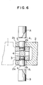
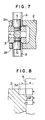
- the universal joint of the invention having the described construction is assembled in a manner which will be explained hereinunder with reference to Figs. 6 and 7.
- the connecting piece 3 is placed between the forks la and 2a of the first and second joint barrels 1 and 2 such that all the surfaces are covered.
- the pivot shaft 4 is inserted into the bore 3a (see F ig. 1) through the hole lb formed in the fork la, while correctly orienting the oil groove 4a. In this state, a certain clearance is left between the wall of the hole lb and the pivot shaft 4 but the pivot shaft 4 does not come off because it closely fits in the bore 3a of the connecting piece 3.
- These dies A and B have an outside diameter somewhat smaller than the diameter of the hole 2b, and an inside diameter suitable just for making a sliding fit around the pivot shaft segments 5, 6.
- These dies are provided with annular pressing portions A 1 and A 2 , respectively, formed on the inner peripheral parts thereof. These dies A and B are inserted into the holes 2b and are pressed onto the opposing surfaces of the connecting piece 3 around the pivot shaft segments 5, 6 vertically, so that the material of the connecting piece 3 is plastically deformed at the portions around thereof disposed the pivot shaft segments 5, 6 such as to cause an increase in the internal pressure. In consequence, an elastic stress greater than the yielding stress of the connecting piece is produced, which tends to cause an outward expansion. As a result, the annular anchoring grooves 4b, 4c are firmly engaged and gripped by the plastically deformed material of the connecting piece 3, so that the pivot shaft segments 5, 6 are securely held by the compacting force and shearing resistance.
- the assembly as a whole is turned 90° and the dies A, B are operated in the same way as explained above, thus securely fixing the other pivot shaft 4 to the connecting piece 3.
- the metal bushes 7 are inserted into the spaces which have been occupied by the dies A, B, thus completing the assembly of the universal joint.
- the sizes of all the portions shown in Fig. 8 are preferably determined to meet the following conditions.
- the axial width S of each anchoring groove i.e., one half of the whole axial width of the double grooves, is calculated as follows:
- the width S is calculated to be about 0.3 mm.
- the radial width L is calculated to be about 0.5 mm.
- the height or depth H is calculated to be about 0.4 mm.
- the apex angle 6 of the double groove is usually selected to be 90° and each groove preferably has a circularly arcuate groove bottom.
- the height or depth H is selected preferably selected such that the bottom of the recess 3d is slightly above or almost at the same level as the top of the double grooves.
- connection thus obtained exhibits a high resistance to vibration because the connecting piece 3 are fixed to both pivot shafts 4 and 5, 6 firmly without any play.
- connection itself is achieved by a cold plastic flow of the metallic material of the connecting piece 3, a high precision can be obtained because of elimination of any unfavourable effect which may otherwise be caused by heat during the work.
- connection can be achieved with a high mass-producibilit; by quite a simple press work which can be conducted without substantial difficulty even by who lacks substantial experience or skill.
- the pivot shafts can be fixed after they are assembled together with the connecting piece, so that the connecting piece can be held securely and with a high precision by the forks of the joint barrels without substantial play.
- the oil grooves 4a, 5a and 6a are arranged in quite a reasonable way with respect to the lubricating oil port 3c so that the metal bush 7 is lubricated smoothly.
- the annular recesses 3d formed by the dies effectively serve as oil wells so that lubrication is conducted in quite a stable manner.
- the joint barrel is constituted by a tubular member, this is not exclusive and the joint barrel may be constituted by a cylindrical member having a fork. It is also possible to use materials other than metals as the material of the joint barrel, provided that such materials can provide strength which is equivalent to the metals. It is also possible to have such an arrangement that both pivot shafts are composec of pairs of segments whereby these segments are inserted from all four directions until they abut at the central portion of the connecting piece.
- pivot shafts need not always be contacted by each othe J and the arrangement may be such that segments of pivot shaft or shafts abut steps or seats formed in the bores and then fixed by the plastic deformation of the wall of the bores
- the anchoring grooves on the pivot shaft may be in the form of serrations but the outside diameter of the projections between adjacent grooves should not project beyond the outside diameter of the pivot shaft.
- the invention provides a universal joint which is easy to assemble and which operates with high reliability.
Landscapes
- Engineering & Computer Science (AREA)
- General Engineering & Computer Science (AREA)
- Mechanical Engineering (AREA)
- Forging (AREA)
- Pivots And Pivotal Connections (AREA)
Applications Claiming Priority (2)
| Application Number | Priority Date | Filing Date | Title |
|---|---|---|---|
| JP59088304A JPS60234125A (ja) | 1984-05-04 | 1984-05-04 | ユニバ−サルジヨイントとその製法 |
| JP88304/84 | 1984-05-04 |
Publications (2)
| Publication Number | Publication Date |
|---|---|
| EP0160319A2 true EP0160319A2 (de) | 1985-11-06 |
| EP0160319A3 EP0160319A3 (de) | 1986-01-15 |
Family
ID=13939185
Family Applications (1)
| Application Number | Title | Priority Date | Filing Date |
|---|---|---|---|
| EP85105386A Withdrawn EP0160319A3 (de) | 1984-05-04 | 1985-05-03 | Kreuzgelenk |
Country Status (3)
| Country | Link |
|---|---|
| EP (1) | EP0160319A3 (de) |
| JP (1) | JPS60234125A (de) |
| AU (1) | AU4177985A (de) |
Cited By (10)
| Publication number | Priority date | Publication date | Assignee | Title |
|---|---|---|---|---|
| GB2361983A (en) * | 2000-05-01 | 2001-11-07 | Torrington Co | Universal Joint Spider |
| FR2902357A1 (fr) * | 2006-06-20 | 2007-12-21 | Fuji Autotech France Sas Soc P | Procede d'obtention d'un alesage de precision dans une aile de fourche de cadran, procede correspondant de fabrication d'une fourche de cardan, et fourche de cardan ainsi obtenue |
| US7338273B2 (en) * | 2002-05-15 | 2008-03-04 | Kobe Steel, Ltd. | Cutter machine |
| WO2011107609A1 (de) * | 2010-03-05 | 2011-09-09 | Automatik Plastics Machinery Gmbh | Schneidvorrichtung für einen granulator zum schneiden von granulat |
| US8500565B2 (en) | 2011-03-14 | 2013-08-06 | Omar Associates, Llc | Non-collinear shaft coupling |
| WO2017093044A1 (de) * | 2015-11-30 | 2017-06-08 | Robert Bosch Gmbh | Verfahren zur herstellung einer pendelanordnung einer pendellaservorrichtung sowie pendellaservorrichtung |
| CN110815254A (zh) * | 2019-12-06 | 2020-02-21 | 深圳优艾智合机器人科技有限公司 | 一种柔性结构、柔性连接件、执行机构、机械臂及机器人 |
| CN110948435A (zh) * | 2019-11-22 | 2020-04-03 | 广东电网有限责任公司 | 一种间隔棒拆装工具 |
| US20210156434A1 (en) * | 2014-08-22 | 2021-05-27 | Re-Dai Precision Tools Co., Ltd. | Elastic short-pin type universal joint |
| CN115247677A (zh) * | 2021-04-27 | 2022-10-28 | 赛莱默欧洲有限公司 | 一种自动补偿联轴器 |
Families Citing this family (2)
| Publication number | Priority date | Publication date | Assignee | Title |
|---|---|---|---|---|
| US6893350B2 (en) * | 2003-05-08 | 2005-05-17 | American Axle & Manufacturing, Inc. | Universal joint with torsionally-compliant spider assembly |
| US7641560B1 (en) * | 2006-10-16 | 2010-01-05 | Drum Workshop, Inc. | Take-up in drum actuation drive trains |
Family Cites Families (4)
| Publication number | Priority date | Publication date | Assignee | Title |
|---|---|---|---|---|
| GB962808A (en) * | 1960-07-11 | 1964-07-01 | Piatti Sanzio Pio Vincenzo | Improvements in universal joints |
| US3313127A (en) * | 1964-01-20 | 1967-04-11 | Vincenzo Sanzio Pio | Universal joints |
| GB1146663A (en) * | 1965-06-01 | 1969-03-26 | Clifford Grundy | Improvements in universal joints |
| US3930381A (en) * | 1974-01-24 | 1976-01-06 | Alves Precision Engineered Products, Inc. | Universal joint |
-
1984
- 1984-05-04 JP JP59088304A patent/JPS60234125A/ja active Pending
-
1985
- 1985-04-29 AU AU41779/85A patent/AU4177985A/en not_active Abandoned
- 1985-05-03 EP EP85105386A patent/EP0160319A3/de not_active Withdrawn
Cited By (19)
| Publication number | Priority date | Publication date | Assignee | Title |
|---|---|---|---|---|
| GB2361983A (en) * | 2000-05-01 | 2001-11-07 | Torrington Co | Universal Joint Spider |
| US6383081B1 (en) | 2000-05-01 | 2002-05-07 | The Torrington Company | Spider for use in a compact universal joint assembly |
| GB2361983B (en) * | 2000-05-01 | 2004-05-12 | Torrington Co | A spider for use in a compact universal joint assembly |
| US7338273B2 (en) * | 2002-05-15 | 2008-03-04 | Kobe Steel, Ltd. | Cutter machine |
| FR2902357A1 (fr) * | 2006-06-20 | 2007-12-21 | Fuji Autotech France Sas Soc P | Procede d'obtention d'un alesage de precision dans une aile de fourche de cadran, procede correspondant de fabrication d'une fourche de cardan, et fourche de cardan ainsi obtenue |
| EP1870180A1 (de) * | 2006-06-20 | 2007-12-26 | Fuji Autotech France SAS | Verfahren zum Präzisionsbohren in einem Flügel einer Kardangelenkgabel, entsprechendes Verfahren zur Herstellung einer Kardangelenkgabel und so erhaltene Kardangelenkgabel |
| TWI490103B (zh) * | 2010-03-05 | 2015-07-01 | Automatik Plastics Machinery | 用以切割粒狀物的造粒機切割器裝置 |
| CN102791450A (zh) * | 2010-03-05 | 2012-11-21 | 奥托马蒂克塑料机械有限公司 | 用于通过切割获取颗粒的造粒机的切割装置 |
| US8851410B2 (en) | 2010-03-05 | 2014-10-07 | Automatik Plastics Machinery Gmbh | Cutting device for a granulator for obtaining granules by cutting |
| CN102791450B (zh) * | 2010-03-05 | 2015-04-08 | 奥托马蒂克塑料机械有限公司 | 用于通过切割获取颗粒的造粒机的切割装置 |
| WO2011107609A1 (de) * | 2010-03-05 | 2011-09-09 | Automatik Plastics Machinery Gmbh | Schneidvorrichtung für einen granulator zum schneiden von granulat |
| US8500565B2 (en) | 2011-03-14 | 2013-08-06 | Omar Associates, Llc | Non-collinear shaft coupling |
| US8635779B2 (en) | 2011-03-14 | 2014-01-28 | Omar Associates, Llc | Method of servicing a coupling connecting two non-collinear shafts |
| US20210156434A1 (en) * | 2014-08-22 | 2021-05-27 | Re-Dai Precision Tools Co., Ltd. | Elastic short-pin type universal joint |
| WO2017093044A1 (de) * | 2015-11-30 | 2017-06-08 | Robert Bosch Gmbh | Verfahren zur herstellung einer pendelanordnung einer pendellaservorrichtung sowie pendellaservorrichtung |
| US10704906B2 (en) | 2015-11-30 | 2020-07-07 | Robert Bosch Gmbh | Method for producing a pendulum arrangement of a pendulum laser device, and pendulum laser device |
| CN110948435A (zh) * | 2019-11-22 | 2020-04-03 | 广东电网有限责任公司 | 一种间隔棒拆装工具 |
| CN110815254A (zh) * | 2019-12-06 | 2020-02-21 | 深圳优艾智合机器人科技有限公司 | 一种柔性结构、柔性连接件、执行机构、机械臂及机器人 |
| CN115247677A (zh) * | 2021-04-27 | 2022-10-28 | 赛莱默欧洲有限公司 | 一种自动补偿联轴器 |
Also Published As
| Publication number | Publication date |
|---|---|
| AU4177985A (en) | 1985-11-07 |
| EP0160319A3 (de) | 1986-01-15 |
| JPS60234125A (ja) | 1985-11-20 |
Similar Documents
| Publication | Publication Date | Title |
|---|---|---|
| EP0331412B1 (de) | Verbindungsvorrichtung und ihr Herstellungsverfahren | |
| EP1239986B1 (de) | Schneidkopf und werkzeugkörperzusammenbau | |
| US4376333A (en) | Method of joining members of metal by forced insertion | |
| EP1590515B1 (de) | Schnell herstellbare, ermüdungsbeständige mit schultern versehene drehverbindung | |
| US8142293B2 (en) | Universal joint assembly for an automotive driveline system | |
| JPH0262731B2 (de) | ||
| GB2116672A (en) | Universal joints | |
| JP2000190242A (ja) | 締りばめ継手、同継手を用いる方法および割出し可能なラチェット・レンチ | |
| US6108895A (en) | Method of axially swaging a male end fitting assembly | |
| US5015136A (en) | Rivet joint and method of manufacture | |
| US4015908A (en) | Multiple-piece crankshaft | |
| JPH041239B2 (de) | ||
| US4678350A (en) | Bearing assembly | |
| JPS60234125A (ja) | ユニバ−サルジヨイントとその製法 | |
| DE4210824A1 (de) | Elastisches Kreuzgelenk | |
| US2841967A (en) | Universal joint | |
| US4887828A (en) | Fixing structure of fork stem and fork shoulder | |
| EP0195150A1 (de) | Satz von Hohlwellen zur Übertragung von Drehmomenten | |
| JPH0233884B2 (de) | ||
| US2904975A (en) | Universal joint | |
| KR102096868B1 (ko) | 수직재 | |
| EP0163296A2 (de) | Sphärisches Lager | |
| US4004434A (en) | Universal joint | |
| US3526950A (en) | Method of assembling elements | |
| JPH08135674A (ja) | 自在継手 |
Legal Events
| Date | Code | Title | Description |
|---|---|---|---|
| PUAI | Public reference made under article 153(3) epc to a published international application that has entered the european phase |
Free format text: ORIGINAL CODE: 0009012 |
|
| AK | Designated contracting states |
Designated state(s): CH DE FR GB IT LI NL SE |
|
| PUAL | Search report despatched |
Free format text: ORIGINAL CODE: 0009013 |
|
| AK | Designated contracting states |
Designated state(s): CH DE FR GB IT LI NL SE |
|
| 17P | Request for examination filed |
Effective date: 19860117 |
|
| 17Q | First examination report despatched |
Effective date: 19860926 |
|
| STAA | Information on the status of an ep patent application or granted ep patent |
Free format text: STATUS: THE APPLICATION HAS BEEN WITHDRAWN |
|
| 18W | Application withdrawn |
Withdrawal date: 19870204 |
|
| RIN1 | Information on inventor provided before grant (corrected) |
Inventor name: YUKITA, HISASHI Inventor name: KANAMARU, HISANOBU Inventor name: SASAYA, KAZUSHI |