EP0160340A2 - Appareil de radiologie muni d'une partie coulissante - Google Patents
Appareil de radiologie muni d'une partie coulissante Download PDFInfo
- Publication number
- EP0160340A2 EP0160340A2 EP85200612A EP85200612A EP0160340A2 EP 0160340 A2 EP0160340 A2 EP 0160340A2 EP 85200612 A EP85200612 A EP 85200612A EP 85200612 A EP85200612 A EP 85200612A EP 0160340 A2 EP0160340 A2 EP 0160340A2
- Authority
- EP
- European Patent Office
- Prior art keywords
- cylinder
- piston
- pressure
- membrane
- counterweight
- Prior art date
- Legal status (The legal status is an assumption and is not a legal conclusion. Google has not performed a legal analysis and makes no representation as to the accuracy of the status listed.)
- Granted
Links
- 239000012528 membrane Substances 0.000 claims abstract description 54
- 239000007788 liquid Substances 0.000 claims description 35
- 238000005096 rolling process Methods 0.000 claims description 19
- 230000005540 biological transmission Effects 0.000 claims description 17
- 239000012530 fluid Substances 0.000 claims description 11
- 238000006073 displacement reaction Methods 0.000 claims description 8
- 230000001133 acceleration Effects 0.000 abstract description 4
- 238000007789 sealing Methods 0.000 abstract description 4
- 230000000694 effects Effects 0.000 abstract description 3
- 230000006835 compression Effects 0.000 description 8
- 238000007906 compression Methods 0.000 description 8
- PEDCQBHIVMGVHV-UHFFFAOYSA-N Glycerine Chemical compound OCC(O)CO PEDCQBHIVMGVHV-UHFFFAOYSA-N 0.000 description 3
- 230000008901 benefit Effects 0.000 description 3
- 230000008859 change Effects 0.000 description 3
- 239000004744 fabric Substances 0.000 description 3
- IJGRMHOSHXDMSA-UHFFFAOYSA-N Atomic nitrogen Chemical compound N#N IJGRMHOSHXDMSA-UHFFFAOYSA-N 0.000 description 2
- 230000001419 dependent effect Effects 0.000 description 2
- 239000007789 gas Substances 0.000 description 2
- 238000004519 manufacturing process Methods 0.000 description 2
- 230000001360 synchronised effect Effects 0.000 description 2
- 235000014676 Phragmites communis Nutrition 0.000 description 1
- 230000009471 action Effects 0.000 description 1
- 230000001154 acute effect Effects 0.000 description 1
- 230000015572 biosynthetic process Effects 0.000 description 1
- 239000000356 contaminant Substances 0.000 description 1
- 230000008878 coupling Effects 0.000 description 1
- 238000010168 coupling process Methods 0.000 description 1
- 238000005859 coupling reaction Methods 0.000 description 1
- 230000002950 deficient Effects 0.000 description 1
- 238000009792 diffusion process Methods 0.000 description 1
- 230000008030 elimination Effects 0.000 description 1
- 238000003379 elimination reaction Methods 0.000 description 1
- 230000009969 flowable effect Effects 0.000 description 1
- 230000006870 function Effects 0.000 description 1
- 238000010438 heat treatment Methods 0.000 description 1
- 239000002184 metal Substances 0.000 description 1
- 238000000034 method Methods 0.000 description 1
- 229910052757 nitrogen Inorganic materials 0.000 description 1
- 230000035515 penetration Effects 0.000 description 1
- 230000036316 preload Effects 0.000 description 1
- 230000008569 process Effects 0.000 description 1
- 230000037303 wrinkles Effects 0.000 description 1
Images

Classifications
-
- A—HUMAN NECESSITIES
- A61—MEDICAL OR VETERINARY SCIENCE; HYGIENE
- A61B—DIAGNOSIS; SURGERY; IDENTIFICATION
- A61B6/00—Apparatus or devices for radiation diagnosis; Apparatus or devices for radiation diagnosis combined with radiation therapy equipment
- A61B6/44—Constructional features of apparatus for radiation diagnosis
- A61B6/4429—Constructional features of apparatus for radiation diagnosis related to the mounting of source units and detector units
Definitions
- the invention relates to an X-ray device with a device part that can be moved thereon and a counterweight that is hydraulically coupled to it and that can be moved in the opposite direction to the device part, and with a cylinder arrangement that serves to transmit hydraulic power.
- Such an X-ray device is known from DE-GM 172 886.
- the counterweight is connected to the piston and the device part - an X-ray target device - to the cylinder.
- the piston divides the cylinder into two parts, which are connected via lines to a liquid pump or the like, so that liquid can be pumped from one part of the piston to the other, with the result that the piston inside the cylinder or the x-ray target device is moved.
- the x-ray target device is held in its position by the counterweight in the idle state, ie when no force acts on it. When a force acts on the target device, the counterweight and the target device first move in opposite directions to one another, so that the user only has to do work at this stage to overcome the acceleration and friction forces.
- X-ray devices are also known in which the device part can be moved by the user by hand (DBP 23 24 699) because the counterweight is always moved in the opposite direction to the X-ray target device.
- the power transmission takes place with the help of ropes that are guided over a number of rollers.
- the forces required to overcome the friction in the ropes can reach unreasonably high values if the device part is heavy.
- the object of the present invention is to design a device of the type mentioned at the outset in such a way that the displacement can be carried out by hand without a pump.
- both the device part and the counterweight are each assigned a cylinder and a piston, of which one part is fixed and the other part is connected to the device part or the counterweight, and that of a piston and a cylinder-enclosed liquid space is connected via a hydraulic connection to the corresponding space enclosed by the other cylinder and the other piston.
- the device part is thus coupled to one of the cylinders or one of the pistons; the same applies to the counterweight.
- the volume enclosed by the associated cylinder and the associated piston changes. This change in volume forces an equal but opposite change in volume in the other cylinder and piston system. If, for example, the volume becomes larger in one system, it becomes smaller in the other system to the same extent. This change in the opposite direction of the liquid volumes enclosed by the cylinders and the pistons enables the device part and counterweight to move in opposite directions.
- piston is to be interpreted broadly in connection with the invention. It is not necessary for the piston, as in the known device, to divide the cylinder into two subspaces; rather, the piston can also have the shape of a tube. It is only important that the piston and the cylinder together close off a volume of liquid to the outside, apart from the opening contained therein for the hydraulic connection between the two systems consisting of cylinder and piston.
- the tension of the membrane could be caused by the fluid pressure of the fluid used for power transmission be generated. However, this presupposes that the liquid is always under pressure.
- this requirement is not met, however, if the X-ray examination device is vertical, so that the compression direction runs horizontally.
- a prestressing of the roller membranes of the two cylinder-piston systems could be generated in that both the device part (X-ray target device) and the counterweight under the action of equally large, mutually canceling forces, which are generated, for example, by means of a spring arrangement and possibly could be transmitted by a thin rope.
- a preferred development of the invention provides that the roller membrane is formed on two sides and is filled with a liquid or gaseous medium, the internal pressure of which is greater than the pressure in the liquid volume used for power transmission.
- the preload of the double-sided roller membrane is generated by the increased pressure in the medium it contains.
- a liquid medium is preferable to a gaseous medium because there is less diffusion loss.
- there is a constant pressure i.e. a constant tension of the roller membrane not to be maintained under all circumstances; A heating of the liquid contained in the rolling membrane could lead to an increase in pressure due to its coefficient of thermal expansion.
- this can be avoided in that the medium is coupled to a memory which is closed off by a membrane and contains gas under pressure.
- the forces that the user must exert in the case of an X-ray device designed in this way depend on the difference in the pressure in the roller membrane on the one hand and in the liquid used for power transmission on the other. The greater this difference, the more forces the user has to apply to move the device part. Since the pressure in the power transmission fluid depends on the inclination of the X-ray examination device in the case of a X-ray examination device which can be folded around a horizontal axis, the pressure difference or the force to be applied by the user to move the device part is also - with constant pressure in the pressure accumulator depending on the respective inclination.
- this dependency can be avoided by providing a container divided by a membrane, one part of which is connected to the liquid used for power transmission and the other part of which is connected to the medium inside the roller membrane, and by means for An additional force is exerted on the membrane in such a way that the pressure in the medium in the rolling membrane is greater than the pressure in the liquid used to transmit the force.
- the pressure difference is determined solely by the additional e.g. force applied to the membrane by means of a spring. By suitably dimensioning this force, the effort required for moving the device part can therefore be kept particularly small for the user.
- the cylinder-piston system In order to achieve a certain displacement between the cylinder and piston with a weight balance, the cylinder-piston system must have a length in the expanded state point that corresponds to around 2.5 times this shift. In order not to let the length of the cylinder-piston system become too long on the one hand and on the other hand to achieve a sufficient displacement path for the device part, a further development of the invention provides that the device part and / or the counterweight with the associated cylinder (piston) a lever arrangement is connected, which is designed such that when the device part or the counterweight is displaced, the cylinder (piston) coupled therewith is displaced to a lesser extent.
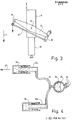
- Fig. 1, 1 denotes the frame of an X-ray examination apparatus which is mounted on the base 2 so as to be pivotable about a horizontal axis.
- a longitudinal carriage 3 can be moved within the frame 1 in its longitudinal direction.
- the longitudinal carriage 3 carries a transverse carriage 4 which can be moved on the longitudinal carriage transversely to the longitudinal direction of the device, ie in the direction of the arrow 5.
- On the cross carriage 4 is an X-ray tube, not shown, on the one hand and on the other hand, an X-ray target device 6 is arranged, which can be moved in the direction of arrow 7, ie perpendicular to the longitudinal and transverse directions - in the so-called compression direction.
- the weight of the longitudinal carriage together with the components carried by it is compensated for with the aid of a main counterweight 8 which can be moved in the longitudinal direction in the frame 1 and which is connected to the longitudinal carriage by means of ropes which are guided over rollers.
- the x-ray target device is coupled to a cylinder 9a, which, together with a piston 10a attached to the transverse carriage 4, encloses a volume of liquid.
- a compression counterweight 12 is coupled in the foot of the device to a cylinder 9b, which together with a piston 10b encloses a liquid volume which communicates with the liquid in the piston 10a and in the cylinder 9a via a hydraulic line in the form of a hose 11.
- the product of the weight 12 and the stroke of this counterweight is equal to the product of the weight of the target device 6 and the stroke of the target device.
- the target device 6 or the counterweight 12 is not coupled directly to the associated cylinder 9a or 9b, but via a lever arrangement in FIG Form of a parallelogram linkage which surrounds the cylinder 10 on two sides, one of which is shown in more detail in FIG. 3.
- the parallelogram linkage comprises a lever 13 which is articulated in the middle at 14 on the cylinder 9 and is articulated at one end to the end of a rod 15 and at the other end to the center of a rod 16.
- a rod 17 is articulated, which has the same length as the lever 13 and the other end of which is articulated to one end of the rod 16 such that the lever 13 and the rods 15, 16 and 17 form a parallelogram form.
- the free end of the rod 16 is articulated at a fixed point on the cross carriage 4 or in the frame 1, in such a way that this articulation point, the point 14 and the point of articulation between the rods 15 and 17 lie in one plane.
- the load i.e.
- the parallelogram linkage causes the cylinder 9 to experience half the stroke when the load is displaced relative to the fixed piston 10, like the load. As already mentioned, this allows the overall length of the cylinder 9-piston 10 system to be kept small.
- the described configuration of the parallelogram linkage also ensures that the articulation point 14 on the cylinder and the point at which the load is articulated always move on parallel (vertical in FIG. 3) straight lines which run in the direction of compression (arrow 7).
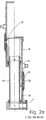
- the structure of a system consisting of cylinder and piston is shown in more detail in FIG. 2a, the system being shown on the right of the center line in a fully compressed state and on the left of the center line in a fully expanded state.
- the piston 10 consists of a Tube, which is provided at its lower end with a connection for the hose 11 (Fig. 1).
- the cylinder 9, which surrounds the piston 10, is closed at its upper end by an end face. Its inside diameter (eg 62 mm) is significantly larger than the outside diameter of the piston 10 (eg 46 mm), so that a relatively large space remains between the piston and the cylinder. This is sealed with the aid of a double-sided roller membrane 18 which surrounds the piston 10.
- the center of this rolling diaphragm is connected to the piston at 19 over the entire circumference.
- Their ends are connected by means of a press ring 20 to the lower end of the cylinder 9 and to a cylinder part 21, which serves only as a guide element and whose inside and outside diameters correspond to the corresponding dimensions of the cylinder 9.
- the two-sided roller membrane 18 thus seals on the one hand the space between the cylinder 9 and the piston 10 and on the other hand delimits a preferably liquid medium, for example glycerol.
- the pressure in this liquid is greater than the pressure in the liquid used for power transmission, the volume of which is limited by the cylinder 9 including its end face on one side of the roller membrane 18 and the piston 10.
- the roller membrane swells outwards and rolls on the inner surfaces and on the outer surface of the piston without wrinkles when the cylinder is displaced.
- the pressure inside the roller membrane also ensures that the cylinder 9 is aligned coaxially with the piston 10.
- the rolling diaphragm would form sharp folds on its side facing this fluid, which would practically block a displacement between the piston and the cylinder.
- the rolling membrane the elasticity of which should be as low as possible at least in the axial direction, can consist of a fabric of threads running in the axial direction, which is sealed on both sides by a rubber skin.
- the flex losses are also determined by the diameter of the inner surface of the cylinder on the one hand and the outer surface of the piston on the other. The greater the difference in diameter, the larger the diameter of the carded fold of the roll membrane and the smaller the flex losses.
- the load on the fabric increases with the size of the annular surface between the piston and the cylinder, so that thicker roller membranes may be required for larger diameter differences.
- the internal pressure in the rolling membrane must be greater than the pressure in the fluid for power transmission. This increased internal pressure can be maintained by hermetically sealing the inside of the rolling membrane from the outside. However, undesirable pressure fluctuations can still occur due to thermal expansion and the low flexibility of the roller membrane. However, these pressure fluctuations can be avoided if the inside of the rolling membrane is connected to a pressure accumulator via an opening 22 provided in the press ring 20. This pressure accumulator is shown schematically in Fig. 2b.
- It consists of a metal vessel 23, which is divided by an elastic membrane 24 into two chambers, of which the chamber 25 is filled with the liquid also in the rolling membrane and via the Outlet 22 communicates with it, while the second chamber, which is hermetically sealed to the outside, contains a pressurized gas, for example nitrogen.
- a pressurized gas for example nitrogen.
- the flex losses are the greater, the greater the pressure difference between the liquid in the rolling membrane and the atmospheric pressure on the one hand or the pressure in the liquid used for power transmission on the other.
- the greatest flexing losses therefore arise in an embodiment with constant pressure in the roll membrane when the table of the X-ray examination apparatus is vertical, because then the pressure in the fluid used for the power transmission is practically zero, so that there is a large pressure difference.
- This disadvantage can be avoided if, instead of a constant (maximum) pressure-generating accumulator, there is a pressure generator that only ever delivers the pressure difference required to maintain the tension of the roller membrane.
- This pressure generator shown in Fig. 2c consists of a vessel 28, which in turn is divided into two parts by a membrane 29, each of which has an outlet 30 and 31, respectively.
- the outlet 31 is connected to the outlet 22 and the outlet 30 to an outlet 32 in the vicinity of the end face of the cylinder 10 by means of a hose, not shown in each case.
- a compression spring 33 is additionally provided, which exerts a pressure on part of the membrane surface. Without this spring, this membrane would always be in such a position that the pressure inside the rolling membrane would be equal to the pressure in the fluid used for power transmission.
- the spring 33 By means of the spring 33, however, the pressure on the chamber provided with the outlet 31 is increased, so that the pressure in the rolling diaphragm is increased by a predetermined one, by the spring force dependent value is greater than the pressure in the fluid used for power transmission.
- the diaphragm 29 In the event of a leak in the roller diaphragm, the diaphragm 29 would be pushed all the way to the right by the spring force. If a suitable switch is placed there, e.g. a reed contact, which is actuated by a magnet on the membrane pushed into the extreme position, can generate an alarm signal.
- a suitable switch e.g. a reed contact, which is actuated by a magnet on the membrane pushed into the extreme position, can generate an alarm signal.
- the pressure in the fluid used for power transmission disappears when the X-ray examination device is pivoted into its vertical position. If the X-ray target device is pulled with little effort in this position, the counterweight can follow this movement. However, if the force acting on the target device 6 exceeds a critical value which corresponds to the product of the atmospheric pressure and the effective piston area, a vacuum or a vacuum is created, so that vapor is formed in the liquid; the counterweight then does not move as quickly as the target device, but follows with a delay and causes an annoyingly noticeable blow when the vapor bubble collapses.
- the desired function of the counterweight is only to support the x-ray target device 6 in the direction 7a (upward).
- a force effect. against this direction is not necessary and its elimination is even an advantage when operating the device vertically, because when the x-ray target device is moved in direction 7, the counterweight 12, once it has moved into its end position, does not participate in the movement and therefore also requires no acceleration forces to be applied by the operator.
- This decoupling in one direction is shown in FIG. 4, which on the one hand achieves the mentioned operating advantage and on the other hand eliminates the blow after vacuum formation mentioned above.
- the hose 11 is connected to an elastic bladder 34, which is located inside a rigid housing 35, which is provided with an opening or with a valve arrangement 36, so that air can flow into the housing and - possibly damped - out of the housing can.
- a force is now exerted in the direction of the arrow 37 or 7a, ie a tensile force on the target device 6 or the cylinder 9a connected to it, the cylinder 9a follows this force, with the increasing volume in the system 9a, 10a resulting from the liquid flowing after the elastic bubble 34 is filled.
- the cylinder 9b does not move relative to the cylinder 10b, ie the counterweight is then no longer coupled to the movements of the target device, which, as mentioned, has the advantage that in this position the user only has to move the mass of the target device.
- Cylinder-piston systems have identical dimensions. With different dimensions of the two systems, different transmission ratios can be achieved (that is, when the cylinder 9a is displaced, the cylinder 9b does not move the same distance), which can be used, if necessary, to counterbalance the weight with smaller counterweights or with smaller cylinder strokes to reach.
- the cylinder surround the piston. Rather, the cylinder could be arranged inside the tubular piston and connected to the piston via a rolling membrane.
- two pistons preferably of different diameters, could also be immersed in opposite directions from one cylinder so that they can penetrate one another.
- the pistons would then have to be closed on both sides by an end face and the cylinder diameter would have to be adjusted in the axial direction so that the center between the inner wall of the cylinder and the outer wall of the piston has the same distance from the cylinder axis.
- a system with more than two collapsible parts with stepped diameters could also be used, between each of which a roller membrane would be arranged. These parts would then be pushed apart or pushed together telescopically during a displacement, with a suitable synchronous selection making it possible to achieve a uniform, synchronous displacement of all the telescopic parts.
Landscapes
- Health & Medical Sciences (AREA)
- Life Sciences & Earth Sciences (AREA)
- Medical Informatics (AREA)
- Engineering & Computer Science (AREA)
- Radiology & Medical Imaging (AREA)
- Molecular Biology (AREA)
- Biophysics (AREA)
- Nuclear Medicine, Radiotherapy & Molecular Imaging (AREA)
- Optics & Photonics (AREA)
- Pathology (AREA)
- Physics & Mathematics (AREA)
- Biomedical Technology (AREA)
- Heart & Thoracic Surgery (AREA)
- High Energy & Nuclear Physics (AREA)
- Surgery (AREA)
- Animal Behavior & Ethology (AREA)
- General Health & Medical Sciences (AREA)
- Public Health (AREA)
- Veterinary Medicine (AREA)
- Actuator (AREA)
- Apparatus For Radiation Diagnosis (AREA)
Applications Claiming Priority (2)
| Application Number | Priority Date | Filing Date | Title |
|---|---|---|---|
| DE19843416000 DE3416000A1 (de) | 1984-04-30 | 1984-04-30 | Roentgengeraet mit einem daran verfahrbaren geraeteteil |
| DE3416000 | 1984-04-30 |
Publications (3)
| Publication Number | Publication Date |
|---|---|
| EP0160340A2 true EP0160340A2 (fr) | 1985-11-06 |
| EP0160340A3 EP0160340A3 (en) | 1987-04-22 |
| EP0160340B1 EP0160340B1 (fr) | 1988-09-07 |
Family
ID=6234670
Family Applications (1)
| Application Number | Title | Priority Date | Filing Date |
|---|---|---|---|
| EP85200612A Expired EP0160340B1 (fr) | 1984-04-30 | 1985-04-19 | Appareil de radiologie muni d'une partie coulissante |
Country Status (4)
| Country | Link |
|---|---|
| US (1) | US4630796A (fr) |
| EP (1) | EP0160340B1 (fr) |
| JP (1) | JPS61330A (fr) |
| DE (2) | DE3416000A1 (fr) |
Cited By (2)
| Publication number | Priority date | Publication date | Assignee | Title |
|---|---|---|---|---|
| WO1989009921A1 (fr) * | 1988-04-08 | 1989-10-19 | L.K. Tool Company Limited | Appareil de commande d'elements dans des machines de mesure |
| US5497408A (en) * | 1993-10-16 | 1996-03-05 | U.S. Philips Corporation | X-ray examination apparatus |
Families Citing this family (4)
| Publication number | Priority date | Publication date | Assignee | Title |
|---|---|---|---|---|
| US4964149A (en) * | 1987-02-09 | 1990-10-16 | Picker International, Inc. | Fluid controlled counterbalance and power-assist for radiation imaging |
| SE457744B (sv) * | 1987-05-29 | 1989-01-23 | Asea Ab | Utbalanseringsenhet foer t ex en roerlig arm i en industrirobot |
| DE4240791A1 (de) * | 1992-12-04 | 1994-06-09 | Philips Patentverwaltung | Röntgengerät mit einem Hydrauliksystem |
| DE102012100179B4 (de) * | 2012-01-11 | 2013-07-18 | Leica Microsystems (Schweiz) Ag | Stativ zum Halten von mindestens einem medizinischen Gerät, insbesondere einem Mikroskop, sowie Anordnung aus einem solchen Stativ und mindestens einem daran befestigten medizinischen Gerät |
Family Cites Families (14)
| Publication number | Priority date | Publication date | Assignee | Title |
|---|---|---|---|---|
| FR324518A (fr) * | 1902-09-17 | 1903-04-03 | Bonnechose Gaston Charles Emil | Joint pour piston |
| DE1728886U (de) * | 1955-04-18 | 1956-08-30 | Siemens Reiniger Werke Ag | Roentgengeraet. |
| US2866101A (en) * | 1955-08-29 | 1958-12-23 | Westinghouse Electric Corp | X-ray apparatus |
| FR1151677A (fr) * | 1956-06-18 | 1958-02-04 | Siegener Eisenbahnbedarf Ag | Dispositif basculant avec accumulateur hydropneumatique de pression pour véhicules |
| FR1307731A (fr) * | 1961-12-08 | 1962-10-26 | Philips Nv | Dispositif support d'une charge déplaçable verticalement à la main |
| GB1057600A (en) * | 1964-08-31 | 1967-02-01 | Gen Electric Co Ltd | Improvements in or relating to counterbalancing arrangements |
| FR1520875A (fr) * | 1966-03-22 | 1968-04-12 | Philips Nv | Dispositif comportant au moins un joint réalisé sous forme de membrane roulante |
| FR1558920A (fr) * | 1967-07-18 | 1969-03-07 | ||
| US3644735A (en) * | 1969-12-31 | 1972-02-22 | Litton Medical Products | Leveling mechanism for x-ray machines |
| BE815016A (fr) * | 1973-05-16 | 1974-11-14 | Appareil pour l'examen aux rayons x | |
| US4166602A (en) * | 1978-05-18 | 1979-09-04 | Pennwalt Corporation | Counterbalancing mechanism for X-ray tubeheads |
| US4241891A (en) * | 1979-04-06 | 1980-12-30 | Unirad Corporation | Overhead arm assembly |
| GB2074337B (en) * | 1980-04-15 | 1983-11-16 | Univ Technology | Adjustable support for an optical or other instrument |
| FR2536733B1 (fr) * | 1982-11-26 | 1986-03-07 | Mongon Systemes | Fleche de grue a portee variable, avec dispositif d'equilibrage automatique |
-
1984
- 1984-04-30 DE DE19843416000 patent/DE3416000A1/de not_active Ceased
-
1985
- 1985-04-19 EP EP85200612A patent/EP0160340B1/fr not_active Expired
- 1985-04-19 DE DE8585200612T patent/DE3564759D1/de not_active Expired
- 1985-04-22 US US06/725,881 patent/US4630796A/en not_active Expired - Fee Related
- 1985-04-27 JP JP60089952A patent/JPS61330A/ja active Granted
Cited By (2)
| Publication number | Priority date | Publication date | Assignee | Title |
|---|---|---|---|---|
| WO1989009921A1 (fr) * | 1988-04-08 | 1989-10-19 | L.K. Tool Company Limited | Appareil de commande d'elements dans des machines de mesure |
| US5497408A (en) * | 1993-10-16 | 1996-03-05 | U.S. Philips Corporation | X-ray examination apparatus |
Also Published As
| Publication number | Publication date |
|---|---|
| EP0160340B1 (fr) | 1988-09-07 |
| DE3416000A1 (de) | 1985-11-07 |
| JPH0529457B2 (fr) | 1993-04-30 |
| EP0160340A3 (en) | 1987-04-22 |
| US4630796A (en) | 1986-12-23 |
| DE3564759D1 (en) | 1988-10-13 |
| JPS61330A (ja) | 1986-01-06 |
Similar Documents
| Publication | Publication Date | Title |
|---|---|---|
| DE2462651B1 (de) | Betonpumpe | |
| WO1988003610A1 (fr) | Cylindre | |
| DE2510410B2 (de) | Regelvorrichtung fuer eine durchbiegungsausgleichswalze | |
| DE2631479A1 (de) | Arbeitskolbenvorrichtung | |
| DE1080876B (de) | Bremskraftregler fuer die Druckluft-bremseinrichtung an Fahrzeugen, insbesondere Kraftfahrzeugen, mit Luftfederung | |
| EP0363788A2 (fr) | Ensemble de pompage | |
| AT519803A2 (de) | Längenverstellbares Pleuel für einen Kolbenmotor | |
| DE2320363C3 (de) | Kalander | |
| DE2105236A1 (de) | Doppeltwirkender hydraulischer Servomotor | |
| DE2629909A1 (de) | Hydraulikzylinder mit eingebautem daempfer unter wiederfuellung der daempfungskammer | |
| EP0160340B1 (fr) | Appareil de radiologie muni d'une partie coulissante | |
| DE2704652A1 (de) | Anordnung zur dornhubbegrenzung bei metallstrang- und rohrpressen | |
| DE2431745A1 (de) | Rollmembrandichtung | |
| DE60116552T2 (de) | Gasfeder mit kontrolliertem Rückzugsverhalten und Einrichtung mit einer solchen Gasfeder | |
| DE1529642B1 (de) | Kraftausgleichseinrichtung | |
| DE3444978A1 (de) | Vorrichtung zur speicherung bzw. uebertragung von energie | |
| DE2147827B2 (de) | Vorrichtung zum Erzeugen akustischer Wellen | |
| DE3126206A1 (de) | Einrichtung zur daempfung von lastpendelbewegungen an kranen | |
| DE1001956B (de) | Hydraulischer Grubenstempel | |
| DE3329832A1 (de) | Einfachwirkender arbeitszylinder | |
| DE3587123T2 (de) | Balgdichtung. | |
| AT408851B (de) | Hydraulische presse | |
| DE2318545A1 (de) | Vorrichtung zur vervielfachung von kraeften | |
| DE3915860C2 (fr) | ||
| DE2336211B2 (de) | Einfach wirkender pneumatischer Arbeitszylinder |
Legal Events
| Date | Code | Title | Description |
|---|---|---|---|
| PUAI | Public reference made under article 153(3) epc to a published international application that has entered the european phase |
Free format text: ORIGINAL CODE: 0009012 |
|
| AK | Designated contracting states |
Designated state(s): DE FR GB IT |
|
| PUAL | Search report despatched |
Free format text: ORIGINAL CODE: 0009013 |
|
| AK | Designated contracting states |
Kind code of ref document: A3 Designated state(s): DE FR GB IT |
|
| 17P | Request for examination filed |
Effective date: 19870720 |
|
| RAP1 | Party data changed (applicant data changed or rights of an application transferred) |
Owner name: N.V. PHILIPS' GLOEILAMPENFABRIEKEN Owner name: PHILIPS PATENTVERWALTUNG GMBH |
|
| 17Q | First examination report despatched |
Effective date: 19871103 |
|
| GRAA | (expected) grant |
Free format text: ORIGINAL CODE: 0009210 |
|
| AK | Designated contracting states |
Kind code of ref document: B1 Designated state(s): DE FR GB IT |
|
| ITF | It: translation for a ep patent filed | ||
| REF | Corresponds to: |
Ref document number: 3564759 Country of ref document: DE Date of ref document: 19881013 |
|
| ET | Fr: translation filed | ||
| GBT | Gb: translation of ep patent filed (gb section 77(6)(a)/1977) | ||
| PLBE | No opposition filed within time limit |
Free format text: ORIGINAL CODE: 0009261 |
|
| STAA | Information on the status of an ep patent application or granted ep patent |
Free format text: STATUS: NO OPPOSITION FILED WITHIN TIME LIMIT |
|
| 26N | No opposition filed | ||
| PGFP | Annual fee paid to national office [announced via postgrant information from national office to epo] |
Ref country code: GB Payment date: 19930401 Year of fee payment: 9 |
|
| PGFP | Annual fee paid to national office [announced via postgrant information from national office to epo] |
Ref country code: FR Payment date: 19930428 Year of fee payment: 9 |
|
| ITTA | It: last paid annual fee | ||
| PGFP | Annual fee paid to national office [announced via postgrant information from national office to epo] |
Ref country code: DE Payment date: 19930628 Year of fee payment: 9 |
|
| PG25 | Lapsed in a contracting state [announced via postgrant information from national office to epo] |
Ref country code: GB Effective date: 19940419 |
|
| GBPC | Gb: european patent ceased through non-payment of renewal fee |
Effective date: 19940419 |
|
| PG25 | Lapsed in a contracting state [announced via postgrant information from national office to epo] |
Ref country code: FR Effective date: 19941229 |
|
| PG25 | Lapsed in a contracting state [announced via postgrant information from national office to epo] |
Ref country code: DE Effective date: 19950103 |
|
| REG | Reference to a national code |
Ref country code: FR Ref legal event code: ST |