EP0160381B1 - Walzwerk - Google Patents
Walzwerk Download PDFInfo
- Publication number
- EP0160381B1 EP0160381B1 EP85301996A EP85301996A EP0160381B1 EP 0160381 B1 EP0160381 B1 EP 0160381B1 EP 85301996 A EP85301996 A EP 85301996A EP 85301996 A EP85301996 A EP 85301996A EP 0160381 B1 EP0160381 B1 EP 0160381B1
- Authority
- EP
- European Patent Office
- Prior art keywords
- rolls
- work
- rolling
- coolant
- mill
- Prior art date
- Legal status (The legal status is an assumption and is not a legal conclusion. Google has not performed a legal analysis and makes no representation as to the accuracy of the status listed.)
- Expired
Links
- 238000005096 rolling process Methods 0.000 title claims abstract description 41
- 239000002826 coolant Substances 0.000 claims abstract description 61
- 239000000314 lubricant Substances 0.000 claims abstract description 41
- 229910052751 metal Inorganic materials 0.000 claims description 11
- 239000002184 metal Substances 0.000 claims description 11
- 238000000034 method Methods 0.000 claims description 9
- 239000007788 liquid Substances 0.000 claims description 7
- XLYOFNOQVPJJNP-UHFFFAOYSA-N water Substances O XLYOFNOQVPJJNP-UHFFFAOYSA-N 0.000 claims description 7
- -1 amine salt Chemical class 0.000 claims description 4
- 229910052783 alkali metal Inorganic materials 0.000 claims description 2
- 150000001732 carboxylic acid derivatives Chemical class 0.000 claims description 2
- 239000000203 mixture Substances 0.000 claims description 2
- 229920001515 polyalkylene glycol Polymers 0.000 claims description 2
- 230000004323 axial length Effects 0.000 claims 2
- 229920002635 polyurethane Polymers 0.000 claims 1
- 239000004814 polyurethane Substances 0.000 claims 1
- 239000007921 spray Substances 0.000 description 6
- 239000012530 fluid Substances 0.000 description 4
- 239000000463 material Substances 0.000 description 4
- 239000004411 aluminium Substances 0.000 description 3
- 229910052782 aluminium Inorganic materials 0.000 description 3
- 238000001816 cooling Methods 0.000 description 3
- 238000005461 lubrication Methods 0.000 description 3
- 239000003595 mist Substances 0.000 description 3
- 238000007789 sealing Methods 0.000 description 3
- XAGFODPZIPBFFR-UHFFFAOYSA-N aluminium Chemical compound [Al] XAGFODPZIPBFFR-UHFFFAOYSA-N 0.000 description 2
- 239000006260 foam Substances 0.000 description 2
- 229920003023 plastic Polymers 0.000 description 2
- 239000004033 plastic Substances 0.000 description 2
- 230000000694 effects Effects 0.000 description 1
- 230000004048 modification Effects 0.000 description 1
- 238000012986 modification Methods 0.000 description 1
- 239000011236 particulate material Substances 0.000 description 1
- 229920000573 polyethylene Polymers 0.000 description 1
- 229920003225 polyurethane elastomer Polymers 0.000 description 1
- 230000002035 prolonged effect Effects 0.000 description 1
- 230000000717 retained effect Effects 0.000 description 1
- 239000011435 rock Substances 0.000 description 1
- 238000010186 staining Methods 0.000 description 1
- 239000002569 water oil cream Substances 0.000 description 1
- 238000009736 wetting Methods 0.000 description 1
Images





Classifications
-
- B—PERFORMING OPERATIONS; TRANSPORTING
- B21—MECHANICAL METAL-WORKING WITHOUT ESSENTIALLY REMOVING MATERIAL; PUNCHING METAL
- B21B—ROLLING OF METAL
- B21B27/00—Rolls, roll alloys or roll fabrication; Lubricating, cooling or heating rolls while in use
- B21B27/06—Lubricating, cooling or heating rolls
- B21B27/10—Lubricating, cooling or heating rolls externally
-
- B—PERFORMING OPERATIONS; TRANSPORTING
- B21—MECHANICAL METAL-WORKING WITHOUT ESSENTIALLY REMOVING MATERIAL; PUNCHING METAL
- B21B—ROLLING OF METAL
- B21B3/00—Rolling materials of special alloys so far as the composition of the alloy requires or permits special rolling methods or sequences ; Rolling of aluminium, copper, zinc or other non-ferrous metals
- B21B2003/001—Aluminium or its alloys
Definitions
- This invention relates to rolling mills and methods of rolling metal in rolling mills.
- the coolant is usually water or is water-based, and includes a rolling lubricant; an oil-water emulsion is frequently employed.
- coolant which preferably contains rolling lubricant
- the coolant is applied to the rolls at the outgoing side ofthe mill by nozzles which are enclosed in casings sealed to the work rolls and ' their back-up rolls by the use of air seals.
- Lubricant contained in the coolant is said to be transferred to the ingoing side of the mill, and thence to the roll gap, through the nip between each work roll and its back-up roll.
- Air seals were employed, evidently because contact seals engaging the work rolls, in particular, were likely to cause damage to the roll surface and hence to the strip. Also the seals would be unable to withstand the high temperature and dryness of the work rolls leaving the roll bite. However, air seals can create a water mist which may escape from the casings adjacent the roll bite and contaminate the rolled product. More importantly, coolant is carried over to the ingoing side of the mill through the work roll/back-up roll bites and delivered by the work rolls to the work at the bite between the work rolls. Consequently, the strip is again contaminated with the disadvantages mentioned above.
- the British specification also has a Figure 3 which shows the rolls at each side of the pass-line enclosed in a casing and coolant/lubricant applied at both the ingoing and the outgoing sides of the mill. Gaps are left between the casings and the work rolls at the roll bite and, according to the provisional specification, the interior of each casing is evacuated with the intention of preventing coolant passing through the gaps to the rolled material. It would however be impossible in practice to obtain in the casings sufficiently low pressures to remove from the work rolls coolant retained thereon by surface tension. Coolant would be carried by the work rolls into the work- roll bite and thence delivered to the surfaces of the strip.
- the coolant is applied only on the ingoing side of the mill in a casing or casings from which unwanted egress of coolant is effectively prevented; because of the direction of rotation of the rolls, there is no possibility of coolant being transferred though the. bite between the work rolls and their back-up rolls and thence to the work at the outgoing side.
- contact seals are used. Such seals, which are more effective than air seals in preventing escape of moisture, are possible because the rolls at the ingoing side of the mill are at a reasonably low temperature and because the contact seals are lubricated by the coolant. No coolant mist is generated and there is no escape route for the mist even if it were generated.
- the contact seals further act as cleaners for the rolls and prevent particulate material being carried into the roll bite by the rolls and damaging the rolls and the work.
- rolling lubricant is applied separately from the coolant at the ingoing side of the mill and outside the casing or casings.
- the separate application of rolling lubricant is essential because of the effectiveness of the contact seals, but, apart from that, it enables the lubricant to be distributed more evenly, makes possible better control of the lubricant, and can result in better efficiency of lubricant usage.
- one aspect of the invention resides in a method of rolling metal in a rolling mill in which liquid coolant is applied to the rolls of the mill only on the ingoing side of the mill, and rolling lubricant is independently applied to the work andfor-the work rolls at the ingoing side of the mill, characterised in that the liquid coolant is directed on to the rolls within casings which extend for the length of the roll barrels and are contact sealed to the rolls to prevent unwanted egress of coolant from the casings and the rolling lubricant is applied to the work and/or the work rolls outside these casings.
- a rolling mill having means for directing liquid coolant on to the rolls on the ingoing side of the mill, and further means for directing rolling lubricant on to the work and/or the workrolls at the ingoing side of the mill, characterised in that said means direct the coolant on to the rolls within casings which extend for the length of the roll barrels and have contact seals in engagement with one or more of the rolls to prevent unwanted egress of coolant from the casings and the further means direct the lubricant on to the work and/or work rolls outside the casings.
- the contact seals are lubricated by the coolant and, when the coolant is mainly water, a useful life of the seals can be obtained.
- a lubricant which is particularly chosen to suit the material of the contact seals, the wear of the seals where they contact the moving rolls is reduced and, thus, the life of the seals. is increased.
- the liquid coolant is water based and the lubricant is miscible therewith.
- the contact seals may be of polyurethane elastomer, in which case the lubricant may be a composition comprising an amine salt or alkali metal salt of a dibasic carboxylic acid and a polyalkylene glycol.
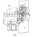
- the mill shown in part in Figures 1 to 8 of the drawings has upper and lower work rolls 12, 13 and upper and lower back-up rolls 14, 15.
- the work - aluminium strip - is indicated at 16, the direction of movement of the work being from left to right, and the strip passing through a guide 17 to the roll gap.
- Coolant is applied to the roll at the ingoing side of the mill, i.e. at the left-hand side of the rolls in the drawing; spray bars 20 and 21 located respectively above and below the pass line extend the full length of the rolls and have at closely spaced intervals sets of spray nozzles 22 directed at the work rolls, the back-up rolls, and the bites between the work rolls and the back-up rolls.
- the spray bars are preferably as described in European Patent No.
- Each spray bar is located within a casing which contains totally the coolant discharged by the nozzles 22 and prohibits the egress of coolant on to the strip 16.
- the upper casing comprises a lower wall 23 secured to the guide 17 and a rear wall 24.
- a contact seal 25 is carried by the casing in a manner to be subsequently described and is urged against back-up roll 14, while a similar contact seal 26 pivoted to the casing is urged against the lower work roll 12 at the bottom of the casing and adjacent the bite between the work rolls.
- the casing and the seals 25 and 26 extend over the whole length of the rolls and the casing carries edge seals 19 which engage against the back-up roll 14 and work roll 12.
- the lower spray bar 21 is contained in a lower, and similar, casing which is generally similar to the upper casing, except that it has an evacuation duct 27 by which coolant is removed from the two casings, which are connected together for that purpose.
- the lower casing is provided with contact seals 30 and 31 and edge seals 19 urged against the lower back-up roll 15 and the lower work roll 13, the mountings for those seals being similar in all respects to those for the upper work and back-up rolls.
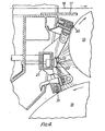
- Each end of the upper casing is provided with arms 40, 41 for mounting the seals 25, 26 respectively.
- a swinging arm 42 is pivoted at 43 to each arm 40 and has a bar 44 fixed thereto, the bar extending transversely across the width of the mill rolls and being formed with a groove 46 (see Figure 3).
- a sealing cartridge 47 comprising a locating bar 48 and a clamping bar 49, the seal 25 being clamped therebetween.
- the bar 44 has a series of cylinders 50 formed therein and pistons 51 in each of these cylinders are normally forced by hydraulic fluid under constant pressure against lugs 52 formed on the casing, to rock the seal carrying bar 44 about the pivot 43 to cause the seal to engage the roll 14.
- the provision of a number of pistons 51 and cylinders 50 along the length of the bar 44 ensures good sealing contact with the roll across its entire length and prevents unwanted egress of coolant.
- the hydraulic fluid is fed into the cylinders 50 by a pipe 53 and a bore 54 connecting each of the cylinders.
- An outlet pipe 55 from the bar 44 feeds the hydraulic fluid to a lower bar 56 where an arrangement somewhat similar to that of the bar 44 is provided.
- the bar 56 is fixed to swinging arms 57 pivoted at 58 to arms 41, and the seal is clamped by a clamping bar 59 to a locating bar 60.
- Pistons 61 acting on lugs 52' formed on the casing urge the seal 26 firmly against the roll 12.
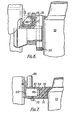
- end seals 19 are provided as shown in Figures 5 to 8, which illustrate the end seals relating to the two lower rolls.
- Attached to the endmost portions of the lower casing are hollow box members 62, each having a rear wall 63, a front wall 64 and a lower wall 65, the front and lower walls being perforated at 66.
- the cavity 67 formed in the box members 62 is connected to a source of vacuum at 68.
- the edge seal 19 is secured to the box member 62 by means of plates 69 fastened by screws 70 to the sides of the box.
- the seal is formed of foamed plastics material 71, being shaped to conform approximately to the contour of the work roll and back-up roll as seen clearly in Figure 5. That part of the seal which is adjacent the nip of the work roll and the back-up roll is formed as a semi-rigid polythene member
- the plastics foam 71 is provided with recesses 76, 77 located around the end portions of the transverse seal cartridges, and the entire edge seal, being of a resilient nature, conforms readily to the roll format and contour. As coolant fluid is wiped from the roll faces by the edge seal, it is sucked from the foam through the perforations 66 and evacuated by the vacuum source at 68.
- the edge seal described above is repeated at each end of the casing and a pair of similar seals are provided in respect of the upper pair of rolls.
- Rolling lubricant is applied to both the work rolls 12 and 13 and to the strip 16 at the ingoing side of the mill and outside the confines of the two casings.
- Lubricant is supplied by two sets of nozzles 80 ( Figure 3) located on opposite sides of the pass line, one set being shown in Figure 3; those nozzles are carried by the bar 56 and the corresponding bar of the lower work roll and are spaced apart over the length of the rolls and directed into the roll bite as shown.
- More effective lubrication of the roll bite is achieved by the separate application of rolling lubricant, than is obtainable by having lubricant included in the coolant.
- the lubricant is more evenly distributed over the width of the rolls and can be more accurately controlled according to the requirements.
- Each of the lubricant nozzles is capable of being controlled independently of the others on a mark/space basis; in other words, each nozzle 80 delivers lubricant in pulses, with the pulse length to duty cycle ratio and frequency being adjusted as required.
- the number and location of the nozzles applying lubricant can be varied according to the width of the strip 16 being rolled and for strip flatness control by varying the cooling effect of the lubricant along the strip width.
- the type of lubricant, and the rate at which it is delivered , by each nozzle can be varied from pass to pass, according to the nature of the metal being rolled.
- the rate at which coolant is delivered by the nozzles 22 and the widthwise distribution of delivered coolant are similarly controllable by the valves supplied for the sets of nozzles, as described in European Patent Application No. 0153532A. Differential cooling of the rolls is thus achieved again to control flatness of the strip.
- seal 100 engaging with the upper work roll 12 may be carried independently of the upper casing 101; the coolant stripped from work roll 12 is collected in receptacle 102 and removed therefrom.
- the contact seal for the upper back-up roll 14 and the edge seals for casing 101 may be as described above.
- lower casing 103 may carry the contact seal 30 for the lower work roll 13 and the casing edge seals.
- contact seal 104 for the lower back-up roll may be carried independently of casing 103 and deliver coolant stripped from that roll into receptacle 104 for removal.
Landscapes
- Engineering & Computer Science (AREA)
- Mechanical Engineering (AREA)
- Metal Rolling (AREA)
- Buildings Adapted To Withstand Abnormal External Influences (AREA)
Claims (12)
Priority Applications (1)
| Application Number | Priority Date | Filing Date | Title |
|---|---|---|---|
| AT85301996T ATE39421T1 (de) | 1984-03-23 | 1985-03-22 | Walzwerk. |
Applications Claiming Priority (2)
| Application Number | Priority Date | Filing Date | Title |
|---|---|---|---|
| GB08407669A GB2156255A (en) | 1984-03-23 | 1984-03-23 | Rolling mill |
| GB8407669 | 1984-03-23 |
Publications (2)
| Publication Number | Publication Date |
|---|---|
| EP0160381A1 EP0160381A1 (de) | 1985-11-06 |
| EP0160381B1 true EP0160381B1 (de) | 1988-12-28 |
Family
ID=10558610
Family Applications (1)
| Application Number | Title | Priority Date | Filing Date |
|---|---|---|---|
| EP85301996A Expired EP0160381B1 (de) | 1984-03-23 | 1985-03-22 | Walzwerk |
Country Status (6)
| Country | Link |
|---|---|
| US (1) | US4671091A (de) |
| EP (1) | EP0160381B1 (de) |
| JP (1) | JPS617009A (de) |
| AT (1) | ATE39421T1 (de) |
| DE (1) | DE3566959D1 (de) |
| GB (1) | GB2156255A (de) |
Families Citing this family (18)
| Publication number | Priority date | Publication date | Assignee | Title |
|---|---|---|---|---|
| GB8514598D0 (en) * | 1985-06-10 | 1985-07-10 | Davy Mckee Poole | Lubrication of rolling mills |
| DE3675985D1 (de) * | 1985-06-10 | 1991-01-17 | Davy Mckee Poole | Schmierung von walzwerken. |
| CH675974A5 (de) * | 1987-10-23 | 1990-11-30 | Lauener Eng Ag | |
| US5046347A (en) * | 1989-10-10 | 1991-09-10 | Alcan International Limited | Coolant containment apparatus for rolling mills |
| US5524465A (en) * | 1991-03-29 | 1996-06-11 | Hitachi, Ltd. | Work rolls crossing type mill, rolling system and rolling method |
| DE10043281B4 (de) * | 2000-04-08 | 2004-04-15 | ACHENBACH BUSCHHüTTEN GMBH | Walzenkühl- und/oder Schmiervorrichtung für Kaltbandwalzwerke, insbesondere Feinband- und Folienwalzwerke |
| DE10131369A1 (de) * | 2001-06-28 | 2003-01-09 | Sms Demag Ag | Verfahren und Vorrichtung zum Kühlen und Schmieren von Walzen eines Walzgerüstes |
| JP4123865B2 (ja) * | 2002-08-12 | 2008-07-23 | 株式会社Ihi | ピンチロールの潤滑ミストスプレー装置 |
| DE10352546A1 (de) * | 2003-09-04 | 2005-03-31 | Sms Demag Ag | Verfahren und Vorrichtung zum Aufbringen einer regelbaren Zugspannungsverteilung, insbesondere in den Kantenbereichen kaltgewalzter Metallbänder |
| US7185522B2 (en) * | 2005-05-10 | 2007-03-06 | T. Sendzimir, Inc. | Side supported 6-high rolling mill |
| US8562766B2 (en) | 2006-02-27 | 2013-10-22 | Nucor Corporation | Method for making a low surface roughness cast strip |
| US20070199627A1 (en) * | 2006-02-27 | 2007-08-30 | Blejde Walter N | Low surface roughness cast strip and method and apparatus for making the same |
| DE102006049161A1 (de) | 2006-10-18 | 2008-04-24 | Sms Demag Ag | Walzgerüst mit Stütz- und/oder Arbeitswalzen zum Walzen von Blechen oder Bändern |
| BE1017462A3 (fr) * | 2007-02-09 | 2008-10-07 | Ct Rech Metallurgiques Asbl | Dispositif et procede de refroidissement de cylindres de laminage en regime hautement turbulent. |
| KR101008112B1 (ko) | 2008-10-24 | 2011-01-13 | 주식회사 포스코 | 선재 냉각용 폴리머 솔루션 및 그 제조방법과 상기 폴리머 솔루션을 이용한 냉각방법 및 그 냉각방법에 의해 제조된 선재 |
| US8966951B2 (en) * | 2009-02-02 | 2015-03-03 | Siemens Vai Metals Technologies Sas | Spraying method and device for a rolling plant |
| DE102012216570A1 (de) * | 2012-05-11 | 2013-11-14 | Sms Siemag Ag | Vorrichtung zum Kühlen von Walzen |
| GB2511512B (en) * | 2013-03-05 | 2015-06-10 | Siemens Plc | Cooling device & method |
Family Cites Families (15)
| Publication number | Priority date | Publication date | Assignee | Title |
|---|---|---|---|---|
| US2056433A (en) * | 1933-04-26 | 1936-10-06 | Edgar J Griffiths | Rolling mill |
| US2107541A (en) * | 1934-09-06 | 1938-02-08 | American Rolling Mill Co | Wiping device for rolling mill rolls |
| DE914725C (de) * | 1950-09-15 | 1954-07-08 | Fritz Grah Dipl Ing | Kuehl- und Schmierkammern fuer Walzen |
| FR1289514A (fr) * | 1961-02-20 | 1962-04-06 | Spidem Ste Nle | Dispositif de lubrification et de refroidissement de la surface des cylindres de laminoirs |
| US3208253A (en) * | 1963-05-10 | 1965-09-28 | United States Steel Corp | Control of rolling mill lubricant |
| GB1172373A (en) * | 1967-02-28 | 1969-11-26 | Stell Company Of Wales Ltd | Improvements in or relating to the Cooling of Rolls |
| JPS4744867B1 (de) * | 1968-09-19 | 1972-11-13 | ||
| GB1511247A (en) * | 1974-06-11 | 1978-05-17 | Alcan Res & Dev | Method and apparatus for cooling the rolls of rolling mills |
| SU512810A1 (ru) * | 1974-11-04 | 1976-05-05 | Всесоюзный Научно-Исследовательский И Проектный Институт По Очистке Технологических Газов,Сточных Вод И Использованию Вторичных Энергоресурсов Предприятий Черной Металлургии | Устройство дл охлаждени и очистки поверхности прокатных валков |
| DE3049490A1 (de) * | 1975-07-26 | 1982-07-29 | Achenbach Buschhütten GmbH, 5910 Kreuztal | Vorrichtung zum zonenweisen aufbringen von fliessfaehigen stoffen auf die walzenballen bei walzwerken |
| CH617603A5 (de) * | 1976-10-21 | 1980-06-13 | Escher Wyss Ag | |
| US4247047A (en) * | 1979-01-15 | 1981-01-27 | Schaming Edward J | Modular zoned digital coolant control system for strip mill rolls |
| US4272976A (en) * | 1979-06-05 | 1981-06-16 | Mesta Machine Company | Hot strip rolling mill stand |
| IT1135049B (it) * | 1980-01-25 | 1986-08-20 | Escher Wyss Sa | Cilindro con una superficie cilindrica da riscaldare o raffreddare |
| US4467629A (en) * | 1981-10-02 | 1984-08-28 | Sms Schloemann-Siemag Ag | Method of flattening steel strip in rolling mill |
-
1984
- 1984-03-23 GB GB08407669A patent/GB2156255A/en not_active Withdrawn
-
1985
- 1985-03-22 DE DE8585301996T patent/DE3566959D1/de not_active Expired
- 1985-03-22 AT AT85301996T patent/ATE39421T1/de not_active IP Right Cessation
- 1985-03-22 JP JP60055701A patent/JPS617009A/ja active Pending
- 1985-03-22 EP EP85301996A patent/EP0160381B1/de not_active Expired
- 1985-03-25 US US06/715,938 patent/US4671091A/en not_active Expired - Fee Related
Also Published As
| Publication number | Publication date |
|---|---|
| GB8407669D0 (en) | 1984-05-02 |
| JPS617009A (ja) | 1986-01-13 |
| ATE39421T1 (de) | 1989-01-15 |
| EP0160381A1 (de) | 1985-11-06 |
| US4671091A (en) | 1987-06-09 |
| DE3566959D1 (en) | 1989-02-02 |
| GB2156255A (en) | 1985-10-09 |
Similar Documents
| Publication | Publication Date | Title |
|---|---|---|
| US4671091A (en) | Rolling mill | |
| EP0494212B1 (de) | Kühlvorrichtung für walzwerke | |
| US7159433B2 (en) | Method and device for cooling and lubricating rollers on a rolling stand | |
| US4061010A (en) | Apparatus for cooling the rolls of rolling mills | |
| EP0205296B1 (de) | Schmierung von Walzwerken | |
| EP0313516A1 (de) | Vorrichtung und Verfahren zum Kühlen von Walzen | |
| CA2117481A1 (en) | Process and Apparatus for Applying and Removing Liquid Coolant to Control Temperature of Continuously Moving Metal Strip | |
| EP0794023A3 (de) | Kaltwalzwerk und Kaltwalzverfahren | |
| EP0590682B1 (de) | Walzwerk mit gekreuzten Arbeitswalzen und Walzanlage | |
| EP0205295B1 (de) | Schmierung von Walzwerken | |
| GB1506462A (en) | Processes for cleaning the surfaces of continuously cast strips | |
| US4632722A (en) | Arrangement for applying a surface pressure upon movable workpieces | |
| CA2364078A1 (en) | Method and device for drying and keeping dry especially cold-rolled strip in the delivery area of cold-rolling and strip-rolling plants | |
| US2555021A (en) | Apparatus for lubricating metallic strips | |
| US5849098A (en) | Process and device for the reduction of the amount of liquids remaining on flat stock after a rolling process | |
| JPS60227906A (ja) | 調質圧延装置 | |
| JPS61293604A (ja) | 圧延機の潤滑に関する改良 | |
| CN222369758U (zh) | 一种用于擦拭包括至少一个润滑剂层的轧制带材的设备 | |
| EP0511478A1 (de) | Strasse zum Glühen und Beizen von Rostfreistahlbändern in Durchlaufverfahren | |
| SU768503A1 (ru) | Устройство дл нанесени смазки на рабочую поверхность валков прокатного стана | |
| JPH0615311A (ja) | 継目無鋼管の傾斜圧延方法 | |
| SU1720735A1 (ru) | Устройство дл смазки и охлаждени прокатных валков | |
| JP4000099B2 (ja) | 厚板材軽圧下矯正機のバックアップロール摩耗防止方法 | |
| JPH11254648A (ja) | チャンバドクタブレード式インキ供給装置 | |
| PL134032B1 (en) | Method of drying of rolled strip on reversing mill |
Legal Events
| Date | Code | Title | Description |
|---|---|---|---|
| PUAI | Public reference made under article 153(3) epc to a published international application that has entered the european phase |
Free format text: ORIGINAL CODE: 0009012 |
|
| AK | Designated contracting states |
Designated state(s): AT BE CH DE FR GB IT LI LU NL SE |
|
| 17P | Request for examination filed |
Effective date: 19860502 |
|
| 17Q | First examination report despatched |
Effective date: 19870708 |
|
| GRAA | (expected) grant |
Free format text: ORIGINAL CODE: 0009210 |
|
| AK | Designated contracting states |
Kind code of ref document: B1 Designated state(s): AT BE CH DE FR GB IT LI LU NL SE |
|
| REF | Corresponds to: |
Ref document number: 39421 Country of ref document: AT Date of ref document: 19890115 Kind code of ref document: T |
|
| ITF | It: translation for a ep patent filed | ||
| REF | Corresponds to: |
Ref document number: 3566959 Country of ref document: DE Date of ref document: 19890202 |
|
| ET | Fr: translation filed | ||
| PLBE | No opposition filed within time limit |
Free format text: ORIGINAL CODE: 0009261 |
|
| STAA | Information on the status of an ep patent application or granted ep patent |
Free format text: STATUS: NO OPPOSITION FILED WITHIN TIME LIMIT |
|
| 26N | No opposition filed | ||
| ITTA | It: last paid annual fee | ||
| PGFP | Annual fee paid to national office [announced via postgrant information from national office to epo] |
Ref country code: GB Payment date: 19930318 Year of fee payment: 9 |
|
| PGFP | Annual fee paid to national office [announced via postgrant information from national office to epo] |
Ref country code: SE Payment date: 19930319 Year of fee payment: 9 |
|
| PGFP | Annual fee paid to national office [announced via postgrant information from national office to epo] |
Ref country code: CH Payment date: 19930323 Year of fee payment: 9 |
|
| PGFP | Annual fee paid to national office [announced via postgrant information from national office to epo] |
Ref country code: LU Payment date: 19930324 Year of fee payment: 9 |
|
| PGFP | Annual fee paid to national office [announced via postgrant information from national office to epo] |
Ref country code: DE Payment date: 19930327 Year of fee payment: 9 |
|
| PGFP | Annual fee paid to national office [announced via postgrant information from national office to epo] |
Ref country code: FR Payment date: 19930330 Year of fee payment: 9 |
|
| PGFP | Annual fee paid to national office [announced via postgrant information from national office to epo] |
Ref country code: NL Payment date: 19930331 Year of fee payment: 9 Ref country code: AT Payment date: 19930331 Year of fee payment: 9 |
|
| PGFP | Annual fee paid to national office [announced via postgrant information from national office to epo] |
Ref country code: BE Payment date: 19930414 Year of fee payment: 9 |
|
| EPTA | Lu: last paid annual fee | ||
| PG25 | Lapsed in a contracting state [announced via postgrant information from national office to epo] |
Ref country code: LU Free format text: LAPSE BECAUSE OF NON-PAYMENT OF DUE FEES Effective date: 19940322 Ref country code: GB Effective date: 19940322 Ref country code: AT Effective date: 19940322 |
|
| PG25 | Lapsed in a contracting state [announced via postgrant information from national office to epo] |
Ref country code: SE Free format text: LAPSE BECAUSE OF NON-PAYMENT OF DUE FEES Effective date: 19940323 |
|
| PG25 | Lapsed in a contracting state [announced via postgrant information from national office to epo] |
Ref country code: LI Effective date: 19940331 Ref country code: CH Effective date: 19940331 Ref country code: BE Effective date: 19940331 |
|
| BERE | Be: lapsed |
Owner name: DAVY MCKEE (POOLE) LTD Effective date: 19940331 |
|
| PG25 | Lapsed in a contracting state [announced via postgrant information from national office to epo] |
Ref country code: NL Effective date: 19941001 |
|
| GBPC | Gb: european patent ceased through non-payment of renewal fee |
Effective date: 19940322 |
|
| NLV4 | Nl: lapsed or anulled due to non-payment of the annual fee | ||
| PG25 | Lapsed in a contracting state [announced via postgrant information from national office to epo] |
Ref country code: FR Effective date: 19941130 |
|
| REG | Reference to a national code |
Ref country code: CH Ref legal event code: PL |
|
| PG25 | Lapsed in a contracting state [announced via postgrant information from national office to epo] |
Ref country code: DE Effective date: 19941201 |
|
| REG | Reference to a national code |
Ref country code: FR Ref legal event code: ST |
|
| EUG | Se: european patent has lapsed |
Ref document number: 85301996.6 Effective date: 19941010 |