EP0160463A2 - Ventilelement zur Verwendung in einem Tintenstrahldruckkopf - Google Patents
Ventilelement zur Verwendung in einem Tintenstrahldruckkopf Download PDFInfo
- Publication number
- EP0160463A2 EP0160463A2 EP85302743A EP85302743A EP0160463A2 EP 0160463 A2 EP0160463 A2 EP 0160463A2 EP 85302743 A EP85302743 A EP 85302743A EP 85302743 A EP85302743 A EP 85302743A EP 0160463 A2 EP0160463 A2 EP 0160463A2
- Authority
- EP
- European Patent Office
- Prior art keywords
- valve
- ink
- valve element
- tongue
- jet printer
- Prior art date
- Legal status (The legal status is an assumption and is not a legal conclusion. Google has not performed a legal analysis and makes no representation as to the accuracy of the status listed.)
- Granted
Links
Images


Classifications
-
- F—MECHANICAL ENGINEERING; LIGHTING; HEATING; WEAPONS; BLASTING
- F16—ENGINEERING ELEMENTS AND UNITS; GENERAL MEASURES FOR PRODUCING AND MAINTAINING EFFECTIVE FUNCTIONING OF MACHINES OR INSTALLATIONS; THERMAL INSULATION IN GENERAL
- F16K—VALVES; TAPS; COCKS; ACTUATING-FLOATS; DEVICES FOR VENTING OR AERATING
- F16K99/00—Subject matter not provided for in other groups of this subclass
- F16K99/0001—Microvalves
-
- B—PERFORMING OPERATIONS; TRANSPORTING
- B41—PRINTING; LINING MACHINES; TYPEWRITERS; STAMPS
- B41J—TYPEWRITERS; SELECTIVE PRINTING MECHANISMS, i.e. MECHANISMS PRINTING OTHERWISE THAN FROM A FORME; CORRECTION OF TYPOGRAPHICAL ERRORS
- B41J2/00—Typewriters or selective printing mechanisms characterised by the printing or marking process for which they are designed
- B41J2/005—Typewriters or selective printing mechanisms characterised by the printing or marking process for which they are designed characterised by bringing liquid or particles selectively into contact with a printing material
- B41J2/01—Ink jet
- B41J2/17—Ink jet characterised by ink handling
- B41J2/175—Ink supply systems ; Circuit parts therefor
- B41J2/17596—Ink pumps, ink valves
-
- F—MECHANICAL ENGINEERING; LIGHTING; HEATING; WEAPONS; BLASTING
- F15—FLUID-PRESSURE ACTUATORS; HYDRAULICS OR PNEUMATICS IN GENERAL
- F15C—FLUID-CIRCUIT ELEMENTS PREDOMINANTLY USED FOR COMPUTING OR CONTROL PURPOSES
- F15C5/00—Manufacture of fluid circuit elements; Manufacture of assemblages of such elements integrated circuits
-
- F—MECHANICAL ENGINEERING; LIGHTING; HEATING; WEAPONS; BLASTING
- F16—ENGINEERING ELEMENTS AND UNITS; GENERAL MEASURES FOR PRODUCING AND MAINTAINING EFFECTIVE FUNCTIONING OF MACHINES OR INSTALLATIONS; THERMAL INSULATION IN GENERAL
- F16K—VALVES; TAPS; COCKS; ACTUATING-FLOATS; DEVICES FOR VENTING OR AERATING
- F16K15/00—Check valves
- F16K15/14—Check valves with flexible valve members
- F16K15/16—Check valves with flexible valve members with tongue-shaped laminae
-
- F—MECHANICAL ENGINEERING; LIGHTING; HEATING; WEAPONS; BLASTING
- F16—ENGINEERING ELEMENTS AND UNITS; GENERAL MEASURES FOR PRODUCING AND MAINTAINING EFFECTIVE FUNCTIONING OF MACHINES OR INSTALLATIONS; THERMAL INSULATION IN GENERAL
- F16K—VALVES; TAPS; COCKS; ACTUATING-FLOATS; DEVICES FOR VENTING OR AERATING
- F16K99/00—Subject matter not provided for in other groups of this subclass
- F16K99/0001—Microvalves
- F16K99/0003—Constructional types of microvalves; Details of the cutting-off member
- F16K99/0005—Lift valves
- F16K99/0007—Lift valves of cantilever type
-
- F—MECHANICAL ENGINEERING; LIGHTING; HEATING; WEAPONS; BLASTING
- F16—ENGINEERING ELEMENTS AND UNITS; GENERAL MEASURES FOR PRODUCING AND MAINTAINING EFFECTIVE FUNCTIONING OF MACHINES OR INSTALLATIONS; THERMAL INSULATION IN GENERAL
- F16K—VALVES; TAPS; COCKS; ACTUATING-FLOATS; DEVICES FOR VENTING OR AERATING
- F16K99/00—Subject matter not provided for in other groups of this subclass
- F16K99/0001—Microvalves
- F16K99/0034—Operating means specially adapted for microvalves
- F16K99/0055—Operating means specially adapted for microvalves actuated by fluids
- F16K99/0057—Operating means specially adapted for microvalves actuated by fluids the fluid being the circulating fluid itself, e.g. check valves
-
- F—MECHANICAL ENGINEERING; LIGHTING; HEATING; WEAPONS; BLASTING
- F16—ENGINEERING ELEMENTS AND UNITS; GENERAL MEASURES FOR PRODUCING AND MAINTAINING EFFECTIVE FUNCTIONING OF MACHINES OR INSTALLATIONS; THERMAL INSULATION IN GENERAL
- F16K—VALVES; TAPS; COCKS; ACTUATING-FLOATS; DEVICES FOR VENTING OR AERATING
- F16K99/00—Subject matter not provided for in other groups of this subclass
- F16K2099/0073—Fabrication methods specifically adapted for microvalves
- F16K2099/0074—Fabrication methods specifically adapted for microvalves using photolithography, e.g. etching
-
- F—MECHANICAL ENGINEERING; LIGHTING; HEATING; WEAPONS; BLASTING
- F16—ENGINEERING ELEMENTS AND UNITS; GENERAL MEASURES FOR PRODUCING AND MAINTAINING EFFECTIVE FUNCTIONING OF MACHINES OR INSTALLATIONS; THERMAL INSULATION IN GENERAL
- F16K—VALVES; TAPS; COCKS; ACTUATING-FLOATS; DEVICES FOR VENTING OR AERATING
- F16K99/00—Subject matter not provided for in other groups of this subclass
- F16K2099/0082—Microvalves adapted for a particular use
- F16K2099/0092—Inkjet printers
-
- F—MECHANICAL ENGINEERING; LIGHTING; HEATING; WEAPONS; BLASTING
- F16—ENGINEERING ELEMENTS AND UNITS; GENERAL MEASURES FOR PRODUCING AND MAINTAINING EFFECTIVE FUNCTIONING OF MACHINES OR INSTALLATIONS; THERMAL INSULATION IN GENERAL
- F16K—VALVES; TAPS; COCKS; ACTUATING-FLOATS; DEVICES FOR VENTING OR AERATING
- F16K2200/00—Details of valves
- F16K2200/40—Bleeding means in closed position of the valve, e.g. bleeding passages
- F16K2200/401—Bleeding means in closed position of the valve, e.g. bleeding passages arranged on the closure member
-
- F—MECHANICAL ENGINEERING; LIGHTING; HEATING; WEAPONS; BLASTING
- F16—ENGINEERING ELEMENTS AND UNITS; GENERAL MEASURES FOR PRODUCING AND MAINTAINING EFFECTIVE FUNCTIONING OF MACHINES OR INSTALLATIONS; THERMAL INSULATION IN GENERAL
- F16K—VALVES; TAPS; COCKS; ACTUATING-FLOATS; DEVICES FOR VENTING OR AERATING
- F16K99/00—Subject matter not provided for in other groups of this subclass
- F16K99/0001—Microvalves
- F16K99/0034—Operating means specially adapted for microvalves
-
- Y—GENERAL TAGGING OF NEW TECHNOLOGICAL DEVELOPMENTS; GENERAL TAGGING OF CROSS-SECTIONAL TECHNOLOGIES SPANNING OVER SEVERAL SECTIONS OF THE IPC; TECHNICAL SUBJECTS COVERED BY FORMER USPC CROSS-REFERENCE ART COLLECTIONS [XRACs] AND DIGESTS
- Y10—TECHNICAL SUBJECTS COVERED BY FORMER USPC
- Y10T—TECHNICAL SUBJECTS COVERED BY FORMER US CLASSIFICATION
- Y10T137/00—Fluid handling
- Y10T137/7722—Line condition change responsive valves
- Y10T137/7837—Direct response valves [i.e., check valve type]
- Y10T137/7847—With leak passage
- Y10T137/7848—Permits flow at valve interface
-
- Y—GENERAL TAGGING OF NEW TECHNOLOGICAL DEVELOPMENTS; GENERAL TAGGING OF CROSS-SECTIONAL TECHNOLOGIES SPANNING OVER SEVERAL SECTIONS OF THE IPC; TECHNICAL SUBJECTS COVERED BY FORMER USPC CROSS-REFERENCE ART COLLECTIONS [XRACs] AND DIGESTS
- Y10—TECHNICAL SUBJECTS COVERED BY FORMER USPC
- Y10T—TECHNICAL SUBJECTS COVERED BY FORMER US CLASSIFICATION
- Y10T137/00—Fluid handling
- Y10T137/7722—Line condition change responsive valves
- Y10T137/7837—Direct response valves [i.e., check valve type]
- Y10T137/7879—Resilient material valve
- Y10T137/788—Having expansible port
- Y10T137/7881—Apertured plate
-
- Y—GENERAL TAGGING OF NEW TECHNOLOGICAL DEVELOPMENTS; GENERAL TAGGING OF CROSS-SECTIONAL TECHNOLOGIES SPANNING OVER SEVERAL SECTIONS OF THE IPC; TECHNICAL SUBJECTS COVERED BY FORMER USPC CROSS-REFERENCE ART COLLECTIONS [XRACs] AND DIGESTS
- Y10—TECHNICAL SUBJECTS COVERED BY FORMER USPC
- Y10T—TECHNICAL SUBJECTS COVERED BY FORMER US CLASSIFICATION
- Y10T137/00—Fluid handling
- Y10T137/7722—Line condition change responsive valves
- Y10T137/7837—Direct response valves [i.e., check valve type]
- Y10T137/7879—Resilient material valve
- Y10T137/7888—With valve member flexing about securement
- Y10T137/7891—Flap or reed
Definitions
- This invention relates to micro mechanical valves, and more particularly, to valve elements which are suitable for an ink-jet printer head for jetting ink droplets responsive to the pump action caused by the interaction between electromechanical conversion means and a valve for supplying the ink.
- valve elements for ink-jet printer heads have been described in the U.S. Patent Application Serial No. 274,210 filed on June 16, 1981.
- the conventional valve element is constituted by a disc-like valve seat having a cylindrical ink passage at its center.
- a valve element is positioned over the seat to support a disc-like valve at the center, by arms around the valve and by a ring-like portion.
- the diameter of the valve is greater than the diameter of the ink passage. This difference in diameter is preferably as small as possible in order to facilitate the ink flow in the forward direction. This means that a high accuracy is necessary in superposing the valve seat and the valve component. Accordingly, the assembly of the valve element is difficult. The manufacturing yield of acceptable valve elements is low and variation of the valve characteristics is great.
- the proposed single-unit type valve element includes a valve seat having a fine hole for enabling a passage of fluid ink.
- a valve seat is formed by use of a photoelectroforming technique.
- a support portion supports a valve for covering the hole and for displacing the valve in response to the pressure of ink.
- a valve fixing portion is attached to the support portion of the valve seat. The valve, the support portion, and fixing portion are formed on the valve seat in order to integrate the valve seat, valvq, support portion, and fixing portion, as a single unit.
- a valve element for use in an ink-jet printer head includes a valve member of flat plate.
- the valve member is composed of a flat member and a tongue portion separated from the plate member by a fine slit.
- a valve seat is composed of a flat plate portion, an opening portion provided at a substantially center of the valve seat, and a stopper member projected into the opening portion. The valve seat is formed on the valve member so that the stopper member projected into the opening portion of the valve seat is faced with the tongue portion of the valve member.
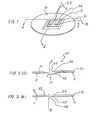
- the first embodiment comprises a valve member 10 of flat plate.
- the valve member 10 is composed of a plate member 11 and a tongue portion 12 separated from the plate member 11 by a fine slit 13, whereby the tongue portion 12 is movable in a vertical direction in Figs. 2(A) and 2(B).
- a valve seat 20 has a thickness of several microns and is composed of a flat plate portion 21, an opening portion 22 provided at its center, and stopper members 23 projected into the opening portion 22. The valve member 10 and the valve seat 20 are positioned so that the stopper members 23 are faced with the tongue portion 12.
- the valve member 10 and the valve seat 20 are formed by means of a photoelectroforming technique including a combination of a patterning tehnique using a photoresist and plating technique.
- Corrosion-resist etals such as nickel, chromium, alminium, and the like, are suitable or use as the metallic materials for the valve member 10 and the valve eat 20.
- ne tongue portion 12 is formed by separating its three sides from the late member 11 by means of the fine slit 13 without cutting the the emaining one side, whereby the tongue portion 12 is movable about the on-separated side in the vertical direction in Figs. 2(A) and 2(B).
- the topper members 23 limit the movement of the tongue portion 12 as shown n Fig. 2(B).
- valve element suitable for an ink-jet printer head is a follows:
- the ink flow is obtained at 25 mm 3 /sec in the forward direction A, and at 2 mm 3 /sec in the reverse direction B, thereby to obtain a forward- reverse ratio of higher than 10. It is experimentally confirmed that the ink-jet printer head has operated at a high droplet-forming frequency of 10KHz.
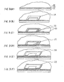
- Figs. 3(A) to 3(1) shows the production process for making the valve element according to the first embodiment.
- a substrate 31 such as a glass
- a first metallic layer 32 of a metal having a high conductivity and adhesive characteristic, such as chromium and alminium is formed by means of a vacuum deposition or spattering technique.
- a second metallic layer 33 of a metal such as nickel or chromium is formed on the first metallic layer 32 by means of a vacuum deposition or spattering technique.
- the metal for the second metallic layer 33 is selected to be same as or able to plate to a plating metal which will be described below.
- a first resist pattern 34 for use in forming the fine slit 13 (Figs. 1 and 2) is formed by means of a photo-lithograph technique. Then, a first plating layer 35 of the plating metal such as nickel or chromium is formed at a portion except for the first resist pattern 34 so that the plating thickness is greater than the thickness of the first resist pattern 34, whereby the plating layer is grown from the both sides of the first resist pattern 34 to form a fine gap 36, as shown in Fig. 3(C).
- a third metallic layer 37 of metal such as alminium capable of selective-etching on the first metallic layer 31 is formed on the whole surface by means of vacuum deposition or spattering technique.
- a second resist pattern 38 is formed by means of photo-lithograph technique. The second resist pattern 38 is used for forming a spacer for separatiang the tongue portion 12 of the valve member 10 from the stopper members 23.
- the third metallic a except for a portion covered by the second resist pattern 38 is removed by means of etching technique and then the second resist pattern 38 is removed.
- a third resist pattern 39 having a thickness of 40 to 50 ⁇ m is formed by means of LAMINAR-AX marketed by DYNACHEM Corporation. This step is for forming the valve seat 20 and the opening portion 22 having a uniform thickness by means of the electroforming technique. Then, a second plating layer 40 having a thickness substantially equal to that of the third resist pattern 39 is formed on whole surface except for the portion covered by the third resist pattern 39, as shown in Fig. 3(H).
- the portions unnecessary for the valve element are removed as shown in Fig. 3(I). More specifically, the glass substrate 31 is removed by dissolving by means of hydrofluoric acid.
- the third resist pattern 39 is removed by dissolveing by means of ALKASTRIP-99A marketed by DYNACHEM Corporation.
- the third and first metallic layers 37 and 32 are removed and then the second metallic layer 33 is removed by means of selective-etching technique. In this case, even when the same metal, for example, nickel is ued as the metals for the first and second plating layers 35 and 40 and the second metallic layer 33, the second metallic layer 33 can be removed without affecting to the first and second plating layers 35 and 40 by using a difference in material and thickness.
- the first resist layer 34 is removed and then a washing is performed.
- the second embodiment comprises first and second tongue portions 12A and 12B positioned symmetricall 0160463 and second two-stopper members 23A and 23B provided in correspondence to the first and second tongue portions 12A and 12B, respectively.
- the third embodiment comprises three opening portions 22' and two stopper members 23' dividing the opening portions 22'.
- the stopper members 23' ensure the stopping operation.
Landscapes
- Engineering & Computer Science (AREA)
- General Engineering & Computer Science (AREA)
- Mechanical Engineering (AREA)
- Chemical & Material Sciences (AREA)
- Dispersion Chemistry (AREA)
- Microelectronics & Electronic Packaging (AREA)
- Computer Hardware Design (AREA)
- Theoretical Computer Science (AREA)
- Physics & Mathematics (AREA)
- Fluid Mechanics (AREA)
- Particle Formation And Scattering Control In Inkjet Printers (AREA)
- Ink Jet (AREA)
- Check Valves (AREA)
Applications Claiming Priority (2)
| Application Number | Priority Date | Filing Date | Title |
|---|---|---|---|
| JP77746/84 | 1984-04-18 | ||
| JP59077746A JPS60222672A (ja) | 1984-04-18 | 1984-04-18 | 弁素子 |
Publications (3)
| Publication Number | Publication Date |
|---|---|
| EP0160463A2 true EP0160463A2 (de) | 1985-11-06 |
| EP0160463A3 EP0160463A3 (en) | 1987-09-16 |
| EP0160463B1 EP0160463B1 (de) | 1990-09-05 |
Family
ID=13642474
Family Applications (1)
| Application Number | Title | Priority Date | Filing Date |
|---|---|---|---|
| EP85302743A Expired - Lifetime EP0160463B1 (de) | 1984-04-18 | 1985-04-18 | Ventilelement zur Verwendung in einem Tintenstrahldruckkopf |
Country Status (4)
| Country | Link |
|---|---|
| US (1) | US4654676A (de) |
| EP (1) | EP0160463B1 (de) |
| JP (1) | JPS60222672A (de) |
| DE (1) | DE3579491D1 (de) |
Cited By (15)
| Publication number | Priority date | Publication date | Assignee | Title |
|---|---|---|---|---|
| EP0339528A1 (de) * | 1988-04-27 | 1989-11-02 | Drägerwerk Aktiengesellschaft | Ventilanordnung aus mikrostrukturierten Komponenten |
| WO1991002169A1 (en) * | 1989-08-11 | 1991-02-21 | Robert Bosch Gmbh | Method of making a microvalve |
| EP0435237A1 (de) * | 1989-12-27 | 1991-07-03 | Honeywell Inc. | Elektrostatisches Miniaturventil und Verfahren zu seiner Herstellung |
| US5176358A (en) * | 1991-08-08 | 1993-01-05 | Honeywell Inc. | Microstructure gas valve control |
| WO1995015873A1 (en) * | 1993-12-06 | 1995-06-15 | Ford Motor Company | Piezoelectric fluid control valve |
| US5441597A (en) * | 1992-12-01 | 1995-08-15 | Honeywell Inc. | Microstructure gas valve control forming method |
| EP0891866A3 (de) * | 1997-07-14 | 1999-04-21 | Owens-Illinois Closure Inc. | Behältnis und Ausgabevorrichtung für Flüssigkeit mit verbessertem Durchflusskontrollventil |
| US6095640A (en) * | 1997-12-05 | 2000-08-01 | Canon Kabushiki Kaisha | Liquid discharge head, liquid discharge method, head cartridge and liquid discharge device |
| AU727463B2 (en) * | 1995-01-13 | 2000-12-14 | Canon Kabushiki Kaisha | Liquid ejecting head, liquid ejecting device and liquid ejecting method |
| US6213592B1 (en) | 1996-06-07 | 2001-04-10 | Canon Kabushiki Kaisha | Method for discharging ink from a liquid jet recording head having a fluid resistance element with a movable member, and head, head cartridge and recording apparatus using that method |
| US6305789B1 (en) | 1995-01-13 | 2001-10-23 | Canon Kabushiki Kaisha | Liquid ejecting head, liquid ejecting device and liquid ejecting method |
| US6464345B2 (en) | 2000-02-15 | 2002-10-15 | Canon Kabushiki Kaisha | Liquid discharging head, apparatus and method employing controlled bubble growth, and method of manufacturing the head |
| US6497475B1 (en) | 1999-09-03 | 2002-12-24 | Canon Kabushiki Kaisha | Liquid discharge method, head, and apparatus which suppress bubble growth at the upstream side |
| US6533400B1 (en) | 1999-09-03 | 2003-03-18 | Canon Kabushiki Kaisha | Liquid discharging method |
| EP2062698A1 (de) | 2007-11-23 | 2009-05-27 | HILTI Aktiengesellschaft | Handwerkzeugmaschine mit Schlagwerkzeugaufnahme und zugeordnetes Werkzeug |
Families Citing this family (13)
| Publication number | Priority date | Publication date | Assignee | Title |
|---|---|---|---|---|
| US4740410A (en) * | 1987-05-28 | 1988-04-26 | The Regents Of The University Of California | Micromechanical elements and methods for their fabrication |
| US4937598A (en) * | 1989-03-06 | 1990-06-26 | Spectra, Inc. | Ink supply system for an ink jet head |
| US5121089A (en) * | 1990-11-01 | 1992-06-09 | Hughes Aircraft Company | Micro-machined switch and method of fabrication |
| MX9601409A (es) * | 1995-04-14 | 1997-08-30 | Canon Kk | Metodo para producir una cabeza de eyeccion de liquido y cabeza de eyeccion de liquido obtenida por dicho metodo. |
| DE19546181C2 (de) * | 1995-12-11 | 1998-11-26 | Fraunhofer Ges Forschung | Mikroventil |
| US6258285B1 (en) * | 1997-07-15 | 2001-07-10 | Silverbrook Research Pty Ltd | Method of manufacture of a pump action refill ink jet printer |
| US6565762B1 (en) * | 1997-07-15 | 2003-05-20 | Silverbrook Research Pty Ltd | Method of manufacture of a shutter based ink jet printer |
| US6264849B1 (en) * | 1997-07-15 | 2001-07-24 | Silverbrook Research Pty Ltd | Method of manufacture of a bend actuator direct ink supply ink jet printer |
| JP3524340B2 (ja) | 1997-08-26 | 2004-05-10 | キヤノン株式会社 | 液体吐出ヘッド |
| US7281785B2 (en) * | 2004-09-17 | 2007-10-16 | Fujifilm Dimatix, Inc. | Fluid handling in droplet deposition systems |
| JP4221611B2 (ja) * | 2006-10-31 | 2009-02-12 | セイコーエプソン株式会社 | 液体噴射ヘッドの製造方法 |
| JP5182785B2 (ja) * | 2007-03-30 | 2013-04-17 | 株式会社吉野工業所 | ポンプ容器 |
| JP2017056090A (ja) * | 2015-09-18 | 2017-03-23 | ニプロ株式会社 | アンチフリーフローバルブ |
Family Cites Families (4)
| Publication number | Priority date | Publication date | Assignee | Title |
|---|---|---|---|---|
| SE355642B (de) * | 1971-08-02 | 1973-04-30 | Stal Refrigeration Ab | |
| US4514742A (en) * | 1980-06-16 | 1985-04-30 | Nippon Electric Co., Ltd. | Printer head for an ink-on-demand type ink-jet printer |
| US4487662A (en) * | 1982-09-20 | 1984-12-11 | Xerox Corporation | Electrodeposition method for check valve |
| JPS59110967A (ja) * | 1982-12-16 | 1984-06-27 | Nec Corp | 弁素子の製造方法 |
-
1984
- 1984-04-18 JP JP59077746A patent/JPS60222672A/ja active Granted
-
1985
- 1985-04-17 US US06/724,099 patent/US4654676A/en not_active Expired - Lifetime
- 1985-04-18 DE DE8585302743T patent/DE3579491D1/de not_active Expired - Lifetime
- 1985-04-18 EP EP85302743A patent/EP0160463B1/de not_active Expired - Lifetime
Cited By (23)
| Publication number | Priority date | Publication date | Assignee | Title |
|---|---|---|---|---|
| EP0339528A1 (de) * | 1988-04-27 | 1989-11-02 | Drägerwerk Aktiengesellschaft | Ventilanordnung aus mikrostrukturierten Komponenten |
| WO1991002169A1 (en) * | 1989-08-11 | 1991-02-21 | Robert Bosch Gmbh | Method of making a microvalve |
| EP0435237A1 (de) * | 1989-12-27 | 1991-07-03 | Honeywell Inc. | Elektrostatisches Miniaturventil und Verfahren zu seiner Herstellung |
| US5176358A (en) * | 1991-08-08 | 1993-01-05 | Honeywell Inc. | Microstructure gas valve control |
| US5323999A (en) * | 1991-08-08 | 1994-06-28 | Honeywell Inc. | Microstructure gas valve control |
| US5441597A (en) * | 1992-12-01 | 1995-08-15 | Honeywell Inc. | Microstructure gas valve control forming method |
| WO1995015873A1 (en) * | 1993-12-06 | 1995-06-15 | Ford Motor Company | Piezoelectric fluid control valve |
| US6305789B1 (en) | 1995-01-13 | 2001-10-23 | Canon Kabushiki Kaisha | Liquid ejecting head, liquid ejecting device and liquid ejecting method |
| US6652076B2 (en) | 1995-01-13 | 2003-11-25 | Canon Kabushiki Kaisha | Liquid ejecting head, liquid ejecting device and liquid ejecting method |
| US6435669B1 (en) | 1995-01-13 | 2002-08-20 | Canon Kabushiki Kaisha | Liquid ejecting head, liquid ejecting device and liquid ejecting method |
| AU727463B2 (en) * | 1995-01-13 | 2000-12-14 | Canon Kabushiki Kaisha | Liquid ejecting head, liquid ejecting device and liquid ejecting method |
| US6213592B1 (en) | 1996-06-07 | 2001-04-10 | Canon Kabushiki Kaisha | Method for discharging ink from a liquid jet recording head having a fluid resistance element with a movable member, and head, head cartridge and recording apparatus using that method |
| EP0891866A3 (de) * | 1997-07-14 | 1999-04-21 | Owens-Illinois Closure Inc. | Behältnis und Ausgabevorrichtung für Flüssigkeit mit verbessertem Durchflusskontrollventil |
| US6692117B1 (en) | 1997-07-14 | 2004-02-17 | Owens-Illinois Closure Inc. | Liquid containment and dispensing device with improved flow control valve |
| US6095640A (en) * | 1997-12-05 | 2000-08-01 | Canon Kabushiki Kaisha | Liquid discharge head, liquid discharge method, head cartridge and liquid discharge device |
| US6439700B1 (en) | 1997-12-05 | 2002-08-27 | Canon Kabushiki Kaisha | Liquid discharge head, liquid discharge method, head cartridge and liquid discharge device |
| US6497475B1 (en) | 1999-09-03 | 2002-12-24 | Canon Kabushiki Kaisha | Liquid discharge method, head, and apparatus which suppress bubble growth at the upstream side |
| US6533400B1 (en) | 1999-09-03 | 2003-03-18 | Canon Kabushiki Kaisha | Liquid discharging method |
| US6854831B2 (en) | 1999-09-03 | 2005-02-15 | Canon Kabushiki Kaisha | Liquid discharge method, liquid discharge head, liquid discharge apparatus, and method for manufacturing liquid discharge head |
| US6945635B2 (en) | 1999-09-03 | 2005-09-20 | Canon Kabushiki Kaisha | Liquid discharge method, liquid discharge head, liquid discharge apparatus, and method for manufacturing liquid discharge head |
| US6464345B2 (en) | 2000-02-15 | 2002-10-15 | Canon Kabushiki Kaisha | Liquid discharging head, apparatus and method employing controlled bubble growth, and method of manufacturing the head |
| EP2062698A1 (de) | 2007-11-23 | 2009-05-27 | HILTI Aktiengesellschaft | Handwerkzeugmaschine mit Schlagwerkzeugaufnahme und zugeordnetes Werkzeug |
| DE102007056531A1 (de) | 2007-11-23 | 2009-05-28 | Hilti Aktiengesellschaft | Handwerkzeugmaschine mit Schlagwerkzeugaufnahme und zugeordnetes Werkzeug |
Also Published As
| Publication number | Publication date |
|---|---|
| EP0160463B1 (de) | 1990-09-05 |
| DE3579491D1 (de) | 1990-10-11 |
| JPH0517997B2 (de) | 1993-03-10 |
| US4654676A (en) | 1987-03-31 |
| JPS60222672A (ja) | 1985-11-07 |
| EP0160463A3 (en) | 1987-09-16 |
Similar Documents
| Publication | Publication Date | Title |
|---|---|---|
| EP0160463A2 (de) | Ventilelement zur Verwendung in einem Tintenstrahldruckkopf | |
| EP0112701B1 (de) | Ventilelement für den Einsatz in einem Tintenstrahldruckkopf | |
| DE60220633T2 (de) | Piezoelektrischer Tintenstrahldruckkopf und Verfahren zu seiner Herstellung | |
| DE69033135T2 (de) | Verfahren zum Schneiden eines Substrates aus Silizium mittels einer preferentiellen Ätzung | |
| DE69009431T2 (de) | Mikropumpe. | |
| US4875968A (en) | Method of fabricating ink jet printheads | |
| JPS61193862A (ja) | シリコン弁とその製作方法 | |
| KR101273436B1 (ko) | 프린트헤드 노즐 형성 | |
| EP1136269A2 (de) | Aus einer Mehrzahl von Einheiten bestehender Tintenstrahldruckkopf und sein Herstellungsverfahren | |
| US4229265A (en) | Method for fabricating and the solid metal orifice plate for a jet drop recorder produced thereby | |
| EP0838005A1 (de) | Verfahren zur herstellung einer membranhaltenden mikrostruktur | |
| US20030080060A1 (en) | Integrated micromachined filter systems and methods | |
| EP0608135A2 (de) | Tintenstrahlkopf | |
| US20070019033A1 (en) | Nozzle for inkjet head and manufacturing method thereof | |
| US7549224B2 (en) | Methods of making slotted substrates | |
| KR100289606B1 (ko) | 잉크젯 프린트헤드용 챔버판의 패터닝방법과 그에 의해 제조되는 액츄에이터 | |
| JP2001179987A (ja) | ノズルプレート及びその製造方法 | |
| KR20090018071A (ko) | 액적 침착 구성요소 | |
| DE19530843A1 (de) | Mikrobearbeitete Ventilöffnung und Ventilsitz mit verbesserter thermischer Isolierung | |
| JP4163075B2 (ja) | ノズルプレートの製造方法 | |
| JP3441129B2 (ja) | 電鋳マスクを用いた噴射加工方法 | |
| KR100327251B1 (ko) | 잉크젯 프린트헤드 액츄에이터와 그의 제조방법 | |
| JPH03121850A (ja) | インクジェットプリンタヘッド及びその製造方法 | |
| JPH0392355A (ja) | インクジェットヘッド製造方法 | |
| CN100474649C (zh) | 保持器的制造方法、致动器的制造方法以及滑动部件的制造方法 |
Legal Events
| Date | Code | Title | Description |
|---|---|---|---|
| PUAI | Public reference made under article 153(3) epc to a published international application that has entered the european phase |
Free format text: ORIGINAL CODE: 0009012 |
|
| 17P | Request for examination filed |
Effective date: 19850507 |
|
| AK | Designated contracting states |
Designated state(s): DE FR GB IT |
|
| PUAL | Search report despatched |
Free format text: ORIGINAL CODE: 0009013 |
|
| AK | Designated contracting states |
Kind code of ref document: A3 Designated state(s): DE FR GB IT |
|
| 17Q | First examination report despatched |
Effective date: 19890125 |
|
| GRAA | (expected) grant |
Free format text: ORIGINAL CODE: 0009210 |
|
| AK | Designated contracting states |
Kind code of ref document: B1 Designated state(s): DE FR GB IT |
|
| REF | Corresponds to: |
Ref document number: 3579491 Country of ref document: DE Date of ref document: 19901011 |
|
| ET | Fr: translation filed | ||
| ITF | It: translation for a ep patent filed | ||
| ITTA | It: last paid annual fee | ||
| PLBE | No opposition filed within time limit |
Free format text: ORIGINAL CODE: 0009261 |
|
| STAA | Information on the status of an ep patent application or granted ep patent |
Free format text: STATUS: NO OPPOSITION FILED WITHIN TIME LIMIT |
|
| 26N | No opposition filed | ||
| REG | Reference to a national code |
Ref country code: GB Ref legal event code: IF02 |
|
| PGFP | Annual fee paid to national office [announced via postgrant information from national office to epo] |
Ref country code: FR Payment date: 20020410 Year of fee payment: 18 |
|
| PGFP | Annual fee paid to national office [announced via postgrant information from national office to epo] |
Ref country code: GB Payment date: 20020417 Year of fee payment: 18 |
|
| PGFP | Annual fee paid to national office [announced via postgrant information from national office to epo] |
Ref country code: DE Payment date: 20020424 Year of fee payment: 18 |
|
| PG25 | Lapsed in a contracting state [announced via postgrant information from national office to epo] |
Ref country code: GB Free format text: LAPSE BECAUSE OF NON-PAYMENT OF DUE FEES Effective date: 20030418 |
|
| PG25 | Lapsed in a contracting state [announced via postgrant information from national office to epo] |
Ref country code: DE Free format text: LAPSE BECAUSE OF NON-PAYMENT OF DUE FEES Effective date: 20031101 |
|
| GBPC | Gb: european patent ceased through non-payment of renewal fee |
Effective date: 20030418 |
|
| PG25 | Lapsed in a contracting state [announced via postgrant information from national office to epo] |
Ref country code: FR Free format text: LAPSE BECAUSE OF NON-PAYMENT OF DUE FEES Effective date: 20031231 |
|
| REG | Reference to a national code |
Ref country code: FR Ref legal event code: ST |