EP0160478A2 - Haut-parleur à bobine mobile - Google Patents
Haut-parleur à bobine mobile Download PDFInfo
- Publication number
- EP0160478A2 EP0160478A2 EP85302793A EP85302793A EP0160478A2 EP 0160478 A2 EP0160478 A2 EP 0160478A2 EP 85302793 A EP85302793 A EP 85302793A EP 85302793 A EP85302793 A EP 85302793A EP 0160478 A2 EP0160478 A2 EP 0160478A2
- Authority
- EP
- European Patent Office
- Prior art keywords
- ring
- drive unit
- build
- coil
- voice coil
- Prior art date
- Legal status (The legal status is an assumption and is not a legal conclusion. Google has not performed a legal analysis and makes no representation as to the accuracy of the status listed.)
- Withdrawn
Links
Images
Classifications
-
- H—ELECTRICITY
- H04—ELECTRIC COMMUNICATION TECHNIQUE
- H04R—LOUDSPEAKERS, MICROPHONES, GRAMOPHONE PICK-UPS OR LIKE ACOUSTIC ELECTROMECHANICAL TRANSDUCERS; ELECTRIC HEARING AIDS; PUBLIC ADDRESS SYSTEMS
- H04R9/00—Transducers of moving-coil, moving-strip, or moving-wire type
- H04R9/06—Loudspeakers
-
- H—ELECTRICITY
- H04—ELECTRIC COMMUNICATION TECHNIQUE
- H04R—LOUDSPEAKERS, MICROPHONES, GRAMOPHONE PICK-UPS OR LIKE ACOUSTIC ELECTROMECHANICAL TRANSDUCERS; ELECTRIC HEARING AIDS; PUBLIC ADDRESS SYSTEMS
- H04R1/00—Details of transducers, loudspeakers or microphones
- H04R1/06—Arranging circuit leads; Relieving strain on circuit leads
Definitions
- the present invention relates to moving coil loudspeakers and is more particularly concerned with the provision of improved methods of interconnecting the component parts of the drive unit for such loudspeakers.
- Moving coil loudspeaker drive units comprise a voice coil wound on a cylindrical former and having fixed thereto a conical section element and a rear suspension element.
- the cylindrical former is located in a radial magnetic field gap and the conical section element provides the main radiating element of the loudspeaker (i.e. the diaphragm).
- the front outer diameter of the diaphragm cone is terminated and suspended in a chassis or basket by a part circular curved section flexible surround.
- the rear suspension for the diaphragm cone is provided by a corrugated flexible element called a spider.
- the suspension elements form the centering mechanism for the coil; as well as a diaphragm restoring force in the case of the rear suspension element and a correct termination arrangement for bending waves in the diaphragm cone itself,.as far as the outer suspension -element is concerned.
- the accurate location of the moving coil in the radial gap magnetic field is of paramount importance for the performance of the loudspeaker drive unit.
- the component parts of the drive unit (coil former, diaphragm and rear suspension or spider) are attached to each other by the use of an adhesive band or bands, or by welding, and the position of the coil on the coil former, relative to the diaphragm and to the magnetic gap, is set by means of build jigs.
- the component parts are generally of soft material and any undue pressure or relaxation during construction of the drive unit will cause them to move relative to each other during the drying out of the adhesive. Further it has been found that two adhesive processes are
- the levels of heat generated from the voice coil can be sufficient to melt the adhesive between the diaphragm and or the suspension spider and the coil former.
- connection to the voice coil in the prior art assembly arrangements, are also generally adhesively bonded to either the diaphragm or the suspension spider. Such connections have to be made by hand after the assembly of the component parts of the drive unit and then bonded to the diaphragm or spider as required. This process does not readily lend itself to automation.
- a moving coil loudspeaker drive unit comprising diaphragm, voice coil, voice coil former and rear suspension spider characterised in that the voice coil former incorporates a component part build-ring adapted to interconnect the rear suspension spider with the coil former and to accurately locate it with respect to the voice coil.
- the build-ring is adapted to connect the diaphragm to the coil former.
- the build-ring is adapted to accommodate a dust dome to envelope the open end of the coil former.
- the build-ring incorporates projections adapted to accommodate electrical connection arrangements for the voice coil.
- the build-ring may also be a separate component or may be formed as part of the voice coil former which may be terminated at end by the build-ring.
- the build-ring may also incorporate robot arm co-operating projections.
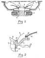
- the loudspeaker unit comprises a chassis or basket 1, a magnetic unit 2 and the moving coil drive unit.
- the drive unit consists of a number of component parts involving a coil former 3 carrying the voice coil 4, a rear suspension spider 5, the loudspeaker diaphragm 6 and a dust dome 8.
- the coil former 3 is terminated at its end remote from the voice coil 4 by a build-ring 7.
- the build-ring is used to provide an interconnection arrangement for the mechanical component parts of the drive unit.
- the rigid build-ring 7 is made from an electrically insulating material.
- the build-ring 7 provides the solution to the problems outlined in the introduction as it is interposed between the three major components (coil former 3, diaphragm 6 and spider 5) of the drive unit without them necessarily being in direct contact with each other.
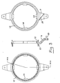
- the build-ring 7 has an upper component locating ring 12 and a lower component locating ring 13 . Also incorporated into the build-ring are projections, such as 9, carrying an electrical connector pin 10 to which flying leads, such as 11, and the coil ends are electrically connected.
- the build-ring 7 is of particular advantage when manufacturing the loudspeaker drive unit as it allows a step- by-step process of assembly to be achieved.
- the coil former 3 is placed inside the lower retaining ring 13 and attached by a suitable adhesive
- the apertured apex of the diaphragm cone is placed outside the upper retaining ring 12 and attached by adhesive bonding.
- the suspension spider 5 is then attached to the outside of the lower retaining ring 13 and adhesively bonded thereto.
- the dust dome 8 is bonded to the inside of the upper retaining ring 12, inside the cone apex aperture.
- the build ring also includes a number of internal projections such as 14. These projections are used to co-operate with an assembly head attached to a machine or robot arm for use in an automated assembly process.
- the build-ring 7 incorporates electrical connection carrying arms such as 9.
- the arms 9 may be adapted to accommodate the voice coil wires in channels such as 15.
- the voice coil wires and flying or flexible lead-out wires 11 are connected to the conducting terminal 10 accommodated in each arm 9.
- no mass or bending moment is applied to the diaphragm and the arms move the connection point away from the diaphragm apex where there is insufficient space to confidently connect the flexible leads to the voice coil wires.
- the projection or arms 9 are provided in a "balanced" manner however they need not all carry terminals and further arms may be introduced to accommodate multiple voice coil connection requirements.
- the build-ring 7 is made from a material which has a high melting point and is suitable for use with high melting point adhesives. This has particular advantage in high energy coil loudspeakers, where the heat generated in conventional loudspeaker construction may lead to relative movement of the coil former and diaphragm and/or suspension spider.
- the rigidity of the build-ring retains the diaphragm/ coil former/suspension spider positions at higher temperatures than is the case of simple inter-bonding.
- the position of the voice coil and the suspension spider relative to the diaphragm and to each other can be guaranteed accurately to within tolerances of manufacture of the individual parts, which are much smaller than those of conventional methods. Furthermore, since the coil former and suspension spider are supported by a rigid ring, they are less susceptible to damage during drive unit and loudspeaker assembly processes.
- Suitable materials for the build-ring are glass fibre reinforced plastics, such as polycarbonate, nylon or polypropylene, with or without a metal reinforcing ring as well as unreinforced versions of the same plastics, or higher temperature plastics such as polymide.
- glass fibre reinforced plastics such as polycarbonate, nylon or polypropylene
- metal reinforcing ring such as polypropylene
- higher temperature plastics such as polymide.
- the choice of material for the build-ring depends on those used for the diaphragm, coil former and suspension spider and should take thermal expansion into account.
- the component parts of the drive unit may be, as defined above, adhesively bonded to the build-ring, however, the upper and lower support rings may be apertured to allow sprung or interference co-operation between the various component parts and the build-ring so that adhesive bonding is not reoried.
- the build-ring may be integrally formed with the coil former or may be located on the coil former at any suitable position other than at the end of the former.
- the build-ring is used to provide an interconnection arrangement for the mechnical component parts of the drive unit.
- the build-ring provides for the accurate location of the component parts of the drive unit and supports these component parts during the drive unit assembly process.
Landscapes
- Physics & Mathematics (AREA)
- Engineering & Computer Science (AREA)
- Acoustics & Sound (AREA)
- Signal Processing (AREA)
- Audible-Bandwidth Dynamoelectric Transducers Other Than Pickups (AREA)
- Diaphragms For Electromechanical Transducers (AREA)
Applications Claiming Priority (2)
| Application Number | Priority Date | Filing Date | Title |
|---|---|---|---|
| GB08410417A GB2160741B (en) | 1984-04-24 | 1984-04-24 | Moving-coil loudspeaker drive unit |
| GB8410417 | 1984-04-24 |
Publications (2)
| Publication Number | Publication Date |
|---|---|
| EP0160478A2 true EP0160478A2 (fr) | 1985-11-06 |
| EP0160478A3 EP0160478A3 (fr) | 1987-08-12 |
Family
ID=10559971
Family Applications (1)
| Application Number | Title | Priority Date | Filing Date |
|---|---|---|---|
| EP85302793A Withdrawn EP0160478A3 (fr) | 1984-04-24 | 1985-04-22 | Haut-parleur à bobine mobile |
Country Status (6)
| Country | Link |
|---|---|
| US (1) | US4680800A (fr) |
| EP (1) | EP0160478A3 (fr) |
| JP (1) | JPS60250800A (fr) |
| CA (1) | CA1258519A (fr) |
| ES (1) | ES8609866A1 (fr) |
| GB (1) | GB2160741B (fr) |
Cited By (3)
| Publication number | Priority date | Publication date | Assignee | Title |
|---|---|---|---|---|
| EP0235991A3 (en) * | 1986-02-14 | 1989-05-24 | Celestion International Limited | Cone loudspeakers |
| DE4005849A1 (de) * | 1989-04-22 | 1990-10-25 | Pioneer Electronic Corp | Konuslautsprecher |
| US7459001B2 (en) * | 2004-03-05 | 2008-12-02 | Natco Norway As | Vane diffuser |
Families Citing this family (17)
| Publication number | Priority date | Publication date | Assignee | Title |
|---|---|---|---|---|
| US5734734A (en) * | 1995-12-29 | 1998-03-31 | Proni; Lucio | Audio voice coil adaptor ring |
| GB2315183A (en) * | 1996-07-09 | 1998-01-21 | B & W Loudspeakers | Coil formers for loudspeaker drive units |
| US6922477B1 (en) * | 1999-11-04 | 2005-07-26 | Matsushita Electric Industrial Co., Ltd. | Speaker |
| AT411558B (de) * | 1999-11-05 | 2004-02-25 | Akg Acoustics Gmbh | Elektroakustischer wandler |
| CA2396260C (fr) * | 2000-01-07 | 2007-09-11 | Lewis Athanas | Transformateur mecanique-acoustique et haut-parleur multimedia a couche mince et plate |
| DE10120281C1 (de) * | 2001-04-25 | 2002-12-05 | Harman Audio Electronic Sys | Lautsprecher |
| KR100491644B1 (ko) * | 2003-03-13 | 2005-05-27 | 에스텍 주식회사 | 스피커 |
| KR20080080258A (ko) * | 2005-05-31 | 2008-09-03 | 에모 라브스, 인크. | 기계-음향 변환기용 최적 압전체 설계 |
| US20100322455A1 (en) * | 2007-11-21 | 2010-12-23 | Emo Labs, Inc. | Wireless loudspeaker |
| US8189851B2 (en) | 2009-03-06 | 2012-05-29 | Emo Labs, Inc. | Optically clear diaphragm for an acoustic transducer and method for making same |
| US20110044476A1 (en) * | 2009-08-14 | 2011-02-24 | Emo Labs, Inc. | System to generate electrical signals for a loudspeaker |
| WO2014143927A2 (fr) | 2013-03-15 | 2014-09-18 | Emo Labs, Inc. | Transducteurs acoustiques |
| USD733678S1 (en) | 2013-12-27 | 2015-07-07 | Emo Labs, Inc. | Audio speaker |
| USD741835S1 (en) | 2013-12-27 | 2015-10-27 | Emo Labs, Inc. | Speaker |
| USD748072S1 (en) | 2014-03-14 | 2016-01-26 | Emo Labs, Inc. | Sound bar audio speaker |
| RU2718683C2 (ru) * | 2018-02-21 | 2020-04-13 | Общество с ограниченной ответственностью "ЛАБОРАТОРИЯ ЗВУКА" | Модульная подвижная система электродинамического громкоговорителя (варианты) |
| WO2021154115A1 (fr) * | 2020-01-31 | 2021-08-05 | Андрей Владимирович ХРОМОВ | Système modulaire mobile de haut-parleur électrodynamique (variantes) |
Family Cites Families (10)
| Publication number | Priority date | Publication date | Assignee | Title |
|---|---|---|---|---|
| GB311071A (en) * | 1928-04-16 | 1929-05-09 | Graham Amplion Ltd | Improvements in or relating to sound reproducing devices |
| FR718905A (fr) * | 1931-06-19 | 1932-01-30 | Support d'équipage mobile pour haut-parleurs électrodynamiques | |
| GB429624A (en) * | 1933-12-12 | 1935-06-04 | Burgess Dempster | Improvements in moving coil loudspeakers |
| GB613287A (en) * | 1946-06-17 | 1948-11-24 | Acoustic Products Ltd | Improvements relating to loudspeakers |
| US2645684A (en) * | 1948-06-30 | 1953-07-14 | Rca Corp | Noise discriminating system |
| GB1162133A (en) * | 1965-09-11 | 1969-08-20 | Emi Ltd | Improvements relating to the manufacture of Loudspeakers |
| US3862376A (en) * | 1973-01-19 | 1975-01-21 | Stanley F White | Cone construction for loudspeaker |
| JPS5389728A (en) * | 1977-01-19 | 1978-08-07 | Sansui Electric Co | Loudspeaker unit |
| JPS53119023A (en) * | 1977-03-26 | 1978-10-18 | Kenzou Inoue | Moving coil type sound converting vibration plate |
| JPS5472031A (en) * | 1977-11-18 | 1979-06-09 | Matsushita Electric Ind Co Ltd | Speaker |
-
1984
- 1984-04-24 GB GB08410417A patent/GB2160741B/en not_active Expired
-
1985
- 1985-04-11 CA CA000478829A patent/CA1258519A/fr not_active Expired
- 1985-04-22 EP EP85302793A patent/EP0160478A3/fr not_active Withdrawn
- 1985-04-23 US US06/726,368 patent/US4680800A/en not_active Expired - Fee Related
- 1985-04-23 JP JP60085587A patent/JPS60250800A/ja active Pending
- 1985-04-24 ES ES542512A patent/ES8609866A1/es not_active Expired
Cited By (3)
| Publication number | Priority date | Publication date | Assignee | Title |
|---|---|---|---|---|
| EP0235991A3 (en) * | 1986-02-14 | 1989-05-24 | Celestion International Limited | Cone loudspeakers |
| DE4005849A1 (de) * | 1989-04-22 | 1990-10-25 | Pioneer Electronic Corp | Konuslautsprecher |
| US7459001B2 (en) * | 2004-03-05 | 2008-12-02 | Natco Norway As | Vane diffuser |
Also Published As
| Publication number | Publication date |
|---|---|
| GB2160741A (en) | 1985-12-24 |
| US4680800A (en) | 1987-07-14 |
| CA1258519A (fr) | 1989-08-15 |
| JPS60250800A (ja) | 1985-12-11 |
| ES8609866A1 (es) | 1986-08-16 |
| EP0160478A3 (fr) | 1987-08-12 |
| ES542512A0 (es) | 1986-08-16 |
| GB8410417D0 (en) | 1984-05-31 |
| GB2160741B (en) | 1988-04-27 |
Similar Documents
| Publication | Publication Date | Title |
|---|---|---|
| US4680800A (en) | Moving-coil loudspeaker unit | |
| JP3021058B2 (ja) | ドームスピーカ | |
| EP2131606B1 (fr) | Haut-parleur | |
| JP3569413B2 (ja) | スピーカ装置及びスピーカ装置の製造方法 | |
| CN108616797A (zh) | 直驱式激励器以及屏幕发声装置 | |
| CN110719554B (zh) | 一种发声装置及其电子设备 | |
| JP2002209295A (ja) | マイクロスピーカー | |
| CN109495819B (zh) | 发声装置和耳机 | |
| CN209134639U (zh) | 一种发声器 | |
| CN110662155A (zh) | 一种发声装置及其发声装置的组装方法 | |
| US20110268310A1 (en) | Loudspeaker with an inverted motor | |
| JP4159408B2 (ja) | スピーカ | |
| US7062061B2 (en) | Speaker apparatus | |
| JP2006352824A (ja) | スピーカ用ボイスコイル及びこのスピーカ用ボイスコイルを用いたスピーカ装置 | |
| CN114979911B (zh) | 发声装置和电子设备 | |
| EP0235838B1 (fr) | Transducteur électrodynamique | |
| EP0610769B1 (fr) | Haut-parleur | |
| JPH0851694A (ja) | センタリング板 | |
| EP3461145B1 (fr) | Terminaux de haut-parleur | |
| US12568336B2 (en) | Loudspeaker | |
| JP3840122B2 (ja) | スピーカの製造方法 | |
| CN208783091U (zh) | 一种扬声器 | |
| KR20260026679A (ko) | 곡선형상의 전극부를 가진 박막 전도체가 형성된 스피커 | |
| KR20260026680A (ko) | 접합온도가 다른 박막 전도체가 형성된 스피커 | |
| KR20260026678A (ko) | 원호형상의 전극부를 가진 박막 전도체가 형성된 스피커 |
Legal Events
| Date | Code | Title | Description |
|---|---|---|---|
| PUAI | Public reference made under article 153(3) epc to a published international application that has entered the european phase |
Free format text: ORIGINAL CODE: 0009012 |
|
| AK | Designated contracting states |
Designated state(s): BE DE FR IT LU NL SE |
|
| PUAL | Search report despatched |
Free format text: ORIGINAL CODE: 0009013 |
|
| AK | Designated contracting states |
Kind code of ref document: A3 Designated state(s): BE DE FR IT LU NL SE |
|
| STAA | Information on the status of an ep patent application or granted ep patent |
Free format text: STATUS: THE APPLICATION IS DEEMED TO BE WITHDRAWN |
|
| 18D | Application deemed to be withdrawn |
Effective date: 19870501 |
|
| RIN1 | Information on inventor provided before grant (corrected) |
Inventor name: SCAIFE, STEPHEN Inventor name: MILLWARD, GARETH Inventor name: BANK, GRAHAM |