EP0160533A2 - Betätigungsorgan mit Formgedächtniseffekt - Google Patents
Betätigungsorgan mit Formgedächtniseffekt Download PDFInfo
- Publication number
- EP0160533A2 EP0160533A2 EP85302953A EP85302953A EP0160533A2 EP 0160533 A2 EP0160533 A2 EP 0160533A2 EP 85302953 A EP85302953 A EP 85302953A EP 85302953 A EP85302953 A EP 85302953A EP 0160533 A2 EP0160533 A2 EP 0160533A2
- Authority
- EP
- European Patent Office
- Prior art keywords
- actuator
- actuator element
- biasing means
- shape memory
- memory alloy
- Prior art date
- Legal status (The legal status is an assumption and is not a legal conclusion. Google has not performed a legal analysis and makes no representation as to the accuracy of the status listed.)
- Granted
Links
Images

Classifications
-
- G—PHYSICS
- G11—INFORMATION STORAGE
- G11B—INFORMATION STORAGE BASED ON RELATIVE MOVEMENT BETWEEN RECORD CARRIER AND TRANSDUCER
- G11B5/00—Recording by magnetisation or demagnetisation of a record carrier; Reproducing by magnetic means; Record carriers therefor
- G11B5/48—Disposition or mounting of heads or head supports relative to record carriers ; arrangements of heads, e.g. for scanning the record carrier to increase the relative speed
- G11B5/4806—Disposition or mounting of heads or head supports relative to record carriers ; arrangements of heads, e.g. for scanning the record carrier to increase the relative speed specially adapted for disk drive assemblies, e.g. assembly prior to operation, hard or flexible disk drives
- G11B5/4833—Structure of the arm assembly, e.g. load beams, flexures, parts of the arm adapted for controlling vertical force on the head
-
- F—MECHANICAL ENGINEERING; LIGHTING; HEATING; WEAPONS; BLASTING
- F03—MACHINES OR ENGINES FOR LIQUIDS; WIND, SPRING, OR WEIGHT MOTORS; PRODUCING MECHANICAL POWER OR A REACTIVE PROPULSIVE THRUST, NOT OTHERWISE PROVIDED FOR
- F03G—SPRING, WEIGHT, INERTIA OR LIKE MOTORS; MECHANICAL-POWER PRODUCING DEVICES OR MECHANISMS, NOT OTHERWISE PROVIDED FOR OR USING ENERGY SOURCES NOT OTHERWISE PROVIDED FOR
- F03G7/00—Mechanical-power-producing mechanisms, not otherwise provided for or using energy sources not otherwise provided for
- F03G7/06—Mechanical-power-producing mechanisms, not otherwise provided for or using energy sources not otherwise provided for using expansion or contraction of bodies due to heating, cooling, moistening, drying or the like
- F03G7/061—Mechanical-power-producing mechanisms, not otherwise provided for or using energy sources not otherwise provided for using expansion or contraction of bodies due to heating, cooling, moistening, drying or the like characterised by the actuating element
- F03G7/0614—Mechanical-power-producing mechanisms, not otherwise provided for or using energy sources not otherwise provided for using expansion or contraction of bodies due to heating, cooling, moistening, drying or the like characterised by the actuating element using shape memory elements
-
- H—ELECTRICITY
- H01—ELECTRIC ELEMENTS
- H01H—ELECTRIC SWITCHES; RELAYS; SELECTORS; EMERGENCY PROTECTIVE DEVICES
- H01H37/00—Thermally-actuated switches
- H01H37/02—Details
- H01H37/32—Thermally-sensitive members
- H01H37/323—Thermally-sensitive members making use of shape memory materials
Definitions
- This invention relates to the field of electromechanical actuators and, particularly, to shape memory effect actuators.
- shape memory alloys in actuators of all types are well known. These actuators typically take advantage of the shape memory effect to trip a switch or break a contact upon reaching a critical temperature.
- a shape memory alloy element is heat treated to form a first shape which is a substantially planar configuration. Once below the alloy's critical temperature, the element may be deformed into a second shape which is arcuate. When the critical temperature is reached during operation, the shape memory alloy will "remember" its first shape and conform, or attempt to conform, to it.
- there is a biasing. member which deforms the shape memory alloy element into the arcuate shape so as to make an electrical contact when below the critical temperature. Upon reaching the critical temperature, the shape memory alloy element returns (or attempts to return) to its planar configuration, displaces the biasing member, and breaks the electrical contact.
- the heat supplied to the actuator may be in the form of electrical resistance or an outside heat source.
- actuators are disclosed in Willson U.S. Patent No. 3,594,674; Willson, U.S.-Patent No. 3,594,675; Willson et al., U.S. Patent No. 3,613,732; Willson et al., U.S. Patent No. 3,634,803; Hickling, U.S. Patent No. 3,849,756; Hart, U.K. Patent Specification 1,554,738; and Hart, U.K. Patent Application 2,024,422A.
- shape memory alloys that have been used with the above actuators are usually either copper-based or nickel/titanium based. These alloys are well known to those skilled in the art.
- the actuator is manually or automatically reset, a common element of all of the above actuators is that the actuator is activated upon reaching the critical temperature which is normally above room temperature. Under certain circumstances, however, it would be desirable to manually position the actuator (without heating it) prior to reaching the critical temperature while also having it automatically resetable.
- biasing member is designed to be stronger than the martensitic shape memory alloy element. Thus, any attempt to manually actuate the actuator by movement of the weaker shape memory alloy element will be overcome by the biasing member.
- the actuator comprises a biasing means which is normally biased in a first position and a shape memory alloy actuator element which is cooperatively engaged with the biasing means.
- the biasing means is a biased arm.
- the shape memory alloy actuator element in a first deactivated condition is biased in the first position by the biasing means.
- the shape memory alloy actuator element in a second unactivated condition biases and retains the biasing means in a second position. In an activating condition the shape memory alloy actuator element also biases the biasing means in the second position.
- shape memory The phenomenon of shape memory is, of course, well known.
- the ability to possess shape memory is a result of the fact that the shape memory alloy undergoes a reversible transformation from an austenitic state to a martensitic state with a change in temperature.
- An article made of such an alloy is easily deformed from its original configuration to a new configuration when cooled below the temperature at which the alloy is tranformed from the austenitic state to the martensitic state.
- the temperature at which this transformation begins is usually referred to as the M s temperature and the temperature at which this transformation is complete is the M f temperature.
- the deformed object When an article thus deformed is warmed to the temperature at which the alloy starts to revert back to austenite, referred to as the As temperature, the deformed object will begin to return to its original configuration. The reversion of the alloy will be complete upon reaching the A f temperature.
- shape memory alloys in actuators are also known as previously discussed. However, as will be explained hereafter, applicants have taken advantage of the unique properties of shape memory alloys to invent a new actuator which can be manually positioned below the M s temperature or activated upon the application of heating to above the As temperature. Thus applicants' shape memory effect actuator represents an improvement of the heretofore described prior art shape memory effect actuators.
- a first aspect of the present invention provides a shape memory effect actuator comprising: a biasing means normally biased in a first position; a shape memory alloy actuator element cooperatively engaged with said biasing means which in a first deactivated condition is biased in said first position by said biasing means, in a second deactivated condition biases and retains said biasing means in a second position, and in activated condition biases said biasing means in said second position.
- a shape memory effect actuator comprising a biasing means, said biasing means being normally biased in a first position and capable of being moved to a second position; an actuator element cooperatively engaged with said biasing means; said actuator element having a first position and a second position corresponding to said first and second positions of said biasing means; said actuator element comprising a shape memory alloy having a martensitic condition and an austenitic condition; in said first position said actuator element is in the martensitic condition and is biased in said first position by said biasing means; in said second position said actuator element biases and retains said biasing means in said second position; said actuator element being in the martensitic condition when moved to said second position by manual manipulation and in the austenitic condition when moved to said second position by the shape memory effect.
- a second aspect of the invention provides a method of assembling an actuator and a cooperating apparatus comprising; assembling an actuator comprising a biasing means cooperatively engaged with a shape memory alloy actuator element wherein the biasing means and actuator element are in a first position; manually moving the biasing means and actuator element to a second position; retaining the biasing means in the second position by the actuator element preferably by physically deforming the actuator element; and mounting the actuator proximate to a cooperating apparatus.
- a third aspect of the invention provides a method of operating an actuator, the actuator comprising a biasing means cooperatively engaged with a shape memory alloy actuator element wherein the biasing means and actuator element are in a first position, the method comprising: manually moving the biasing means and actuator element to a second position; retaining the biasing means in the second position by the actuator element; activating the actuator element by the application of heating means; returning the biasing means and actuator element to the first position; deactivating the actuator element by the removal of the heating means.
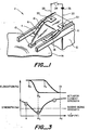
- the actuator comprises a biasing means 4 which is normally biased in a first position.
- the position of the biasing means in the first position is as shown in Figure 2b.
- the actuator further comprises a shape memory alloy actuator element 6 cooperatively engaged with the biasing means 4.
- the actuator element in its first unactivated condition is biased in the first position by the biasing means as shown by Figure 2b.
- the actuator element biases and retains the biasing means in a second position. This is as shown in Figure 2a.
- the actuator element biases the biasing means in the second position, as shown in Figure 2c.
- biasing means is shown as a biased arm; however, other biasing means (not shown) such as helical springs, etc., are contemplated within the scope of the invention.
- Figures 2a and 2c show the actuator in the second position wherein the actuator element lifts or holds up the biasing means.
- the actuator is deactivated and in Figure 2C, the actuator is activated.
- Figure 2b shows the actuator in the first position wherein the biasing means biases the actuator element down and the actuator element is in the deactivated condition.
- the biasing means 4 always has a net force pushing downward whereas the actuator element 6, when activated, has a net force upward.
- the actuator element biases the biasing means while in the deactivated condition
- the biasing means and actuator element must somehow be moved to the second position. While there are various ways that this may occur, a particularly preferred way is to manually move the actuator element and biasing means arm to the second position. It is also necessary to the invention that the shape memory alloy actuator element retain the biasing means arm in this second position after being manually moved there. The means by which the actuator element retains the biasing means in this second position will be described hereafter.
- the shape memory alloy actuator element undergoes the shape memory effect when activated such that the shape memory alloy transforms from the martensitic condition to the austenitic condition when activated by the application of heating means. It is necessary to the invention that the shape memory alloy actuator element returns back to the martensitic condition when deactivated by the application of cooling means. While there are several different forms of heating and cooling means, the preferred means comprise electrical resistance heating and exposure to ambient air, respectively.
- the actuator element When the preferred heating means comprises electrical resistance heating, the actuator element is activated by closing switch 24. Power supply 26 then pushes electric current through the actuator element. When switch 24 is open, the actuator element is said to be in the deactivated condition, regardless of the temperature of the actuator element.
- the heating means is by electrical resistance heating
- the shape memory alloy actuator element have a nonconductive coating (i.e., TeflonR material, which is a registered trademark of E. I. Du Pont) so as to avoid short circuiting the actuator element against the biasing means or any support structure that may be present.
- the shape memory alloy has an M s temperature above room temperature. It is most preferable that the shape memory alloy at room temperature has greater strength than the biasing means at room temperature. The importance of these perferments of the invention will become apparent hereafter.
- the actuator further comprises a support structure 8.
- the biasing means is a biased arm and the actuator element 6 and the biased arm 4 are cantilevered from the support structure.
- the preferred application of the invention is a disc head lifter to be used in conjunction with disc 14 and a disc drive unit (not shown).
- the actuator will comprise a disc read/write head 10, the function of which will be familiar to those skilled in the art.
- the biasing means 4 When used in the preferred application of the invention, the biasing means 4 will be a biased arm 4 and will have a generally triangular shape.
- the shape memory alloy actuator element 6 will have a generally U-shaped configuration such that the biased arm will pass through the "U" of the shape memory alloy actuator element.
- the legs 16,18 of the actuator element 6 are connected by fastening means 20, 22 respectively to the support structure 8.
- suitable leads 28, 30 may be connected at the fastening means 20, 22, respectively.
- Figure 3 shows a graph of the strength of a shape memory alloy actuator element versus temperature.
- the temperatures M s and A f have already been defined in the Background of the Invention.
- Temperature R represents the operating temperature of the actuator which for most situations will be room temperature. It is known that a graph such as this will show a trough near or at the temperature wherein the shape memory alloy goes through the M s temperature. Generally speaking, the magnitude of the difference in strength of the shape memory alloy at points A and B will vary depending upon the alloy.
- a graph of the strength of the biasing means versus temperature which is nominally constant over the temperature ranges considered.
- Figure 3 is a plot of the hysteresis typically exhibited by the shape memory alloy actuator element.
- Figure 3 then, in toto, illustrates the relationship of the strength of the shape memory alloy actuator element to the reversible phase transformation of the shape memory alloy.
- the M s and A f temperatures on the hysteresis correspond to the M s and A f temperatures on the horizontal axis of Figure 3.
- the hysteresis has been determined by measuring elongation versus temperature; a method known to those skilled in the art.
- the actuator comprises a biasing means cooperatively engaged with an actuator element.
- the biasing means is normally in a first position ( Figure 2b) but is capable of being moved to a second position ( Figure 2a or 2c).
- the actuator element has a first position and a second position corresponding to the first and second positions of the biasing means.
- the actuator element comprises a shape memory alloy having a martensitic condition and an austenitic condition.
- the actuator element In the first position the actuator element is in the martensitic condition and is biased in the first position by the biasing means. In the second position, the biasing means is biased by the actuator element. In the second position, the actuator element will be in the martensitic condition when moved to the second position by manual manipulation and in the austenitic condition when moved to the second position by the shape memory effect.
- the actuator element has been heat treated so that in the heat stable austenitic condition, the actuator element will be in the second position.
- the actuator element When the actuator element is in the first posiiton( it will be in the heat unstable martensitic condition.
- the actuator If the actuator is in the first posiiton, the application of sufficient heat (by whatever means) will cause the actuator element to revert to the austenitic condition.
- the actuator element in the austenitic condition has greater strength than the biasing means, as seen at Point C on Figure 3, so that the actuator element (and therefore the actuator) will be in the second position.
- the actuator element When the heat is removed and the actuator element is cooled (either by exposure to ambient air or some other cooling means), the actuator element will go through a strength minimum at M s , as seen at Point B, and transform to the martensitic condition. Since the biasing means is now stronger than the actuator element, the actuator will be in the first position. Further cooling will increase the strength of the actuator element, as seen at Point A, but will not alter its position.
- heat can be applied to move the actuator (by the shape memory effect) to the second position, then heat removed to return the actuator to the first position and so on.
- the actuator element can be manually moved to the second position. Even though the actuator element is in the martensitic condition, the actuator element will lift up and retain the biasing means in the second position due to the greater strength of the actuator element at R.
- the actuator element can actually be moved a considerable distance due to the large amount of deformation that can be recovered upon heating above A f , which is characteristic of shape memory alloys.
- the application of heat will cause the actuator element to first encounter the strength minimum at M s and move to the first position. If the heat is removed, the actuator will remain in the first position. If the heat continues to be applied, the actuator will then move to the second position. Removal of the heat at the second position will cause the actuator to return to the first position, as described above.
- one preferred alloy is the nickel/titanium copper alloy as disclosed in pending U.S. Patent Application No. 537,316 (MP0813-US2) which is hereby incorporated by reference.
- M s will be well above room temperature and the temperature at which the shape memory alloy has greater strength than the biasing means will be around room temperature.
- this preferred alloy will exactly achieve the objects of the invention.
- the room temperature is well below the room temperature normally encountered such as might be the case in a refrigerated room, other shape memory alloys known to those skilled in the art may be substituted for the nickel/titanium/ copper alloy.
- the method comprises assembling an actuator comprising a biasing means 4 cooperatively engaged with a shape memory alloy actuator element 6.
- the biasing means and actuator element are in a first position.
- the next step in the method is manually moving the biasing means and actuator element to the second position.
- the method further comprises retaining the biasing means in the second position by the actuator element.
- the actuator is then mounted proximate to a cooperating apparatus 12.
- this apparatus represents a part of a disc drive unit (not shown).
- the disc head lifter is assembled to the disc drive unit in a manner such that the read/write head 10 and the disc 14 are maintained away from each other to prevent damage to each other during the assembly process.
- the next steps in the method are activating the actuator element 6 by the application of heating means, and then returning the biasing means and actuator element to the first position.
- the final step in the method is unactivating the actuator element by the removal of the heating means.
- the method may also comprise the step of returning the biasing means and actuator element to the second position prior to the step of unactivating the actuator element. This would occur by continuing the application of heating means until the biasing means and actuator element reached the second position.
- the actuator 2 comprises a biasing means 4 cooperatively engaged with the shape memory alloy actuator element 6 wherein-the biasing means and actuator element are in a first position.
- the method comprises first manually moving the biasing means and actuator element to a second position and then retaining the biasing means in the second position by the actuator element.
- the method comprises activating the actuator element by the application of heating means and then returning the biasing means and actuator element to the first position.
- the final step in this method is unactivating the actuator element by the removal of heating means.
- the method may further comprise the step of returning the biasing means and actuator element to the second position prior to the step of unactivating the actuator element. As before, this would occur by -continuing the application of heating means until the biasing means arm and actuator element reached the second position.
- Either of the methods may also comprise at least one operating cycle.
- This operating cycle comprises firstly activating the actuator element while in the first position by the application of heating means and then moving the biasing means and actuator element to the second position. This represents the first half of the cycle.
- the method comprises unactivating the actuator element by the removal of the heating means and then returning the biasing means and actuator element to the first position.
- the first half of the operating cycle comprises activating the actuator element in the first position and then moving the actuator to the second position while the second half of the cycle comprises removal of the heating means and then returning the actuator to the first position.
- the step of retaining the biasing means in the second position by the actuator element comprises deforming the actuator element. In this manner the actuator element in and of itself retains the biasing means in the second position without any additional mechanical arrangements.
- the shape memory alloy actuator element undergoes the shape memory effect when activated such that the shape memory alloy transforms from the martensitic condition to the austenitic condition when activated by the application of heating means and then returns back to the martensitic condition when unactivated by the removal of the heating means.
- the shape memory alloy has an M s temperature above room temperature and at room temperature has greater strength than the biasing means at room temperature.
- the actuator element When the actuator is used in an electrical environment it is preferred that the actuator element has a nonconductive coating so as to avoid short circuiting against the biasing means or any nearby support structure.
Landscapes
- Engineering & Computer Science (AREA)
- Chemical & Material Sciences (AREA)
- Combustion & Propulsion (AREA)
- Mechanical Engineering (AREA)
- General Engineering & Computer Science (AREA)
- Thermal Sciences (AREA)
- Physics & Mathematics (AREA)
- Control Of Position Or Direction (AREA)
- Manipulator (AREA)
- Micromachines (AREA)
- Toys (AREA)
- Thermally Actuated Switches (AREA)
- Shaping By String And By Release Of Stress In Plastics And The Like (AREA)
- Finger-Pressure Massage (AREA)
Priority Applications (1)
| Application Number | Priority Date | Filing Date | Title |
|---|---|---|---|
| AT85302953T ATE49826T1 (de) | 1984-04-27 | 1985-04-26 | Betaetigungsorgan mit formgedaechtniseffekt. |
Applications Claiming Priority (2)
| Application Number | Priority Date | Filing Date | Title |
|---|---|---|---|
| US06/604,784 US4551974A (en) | 1984-04-27 | 1984-04-27 | Shape memory effect actuator and methods of assembling and operating therefor |
| US604784 | 1996-02-23 |
Publications (3)
| Publication Number | Publication Date |
|---|---|
| EP0160533A2 true EP0160533A2 (de) | 1985-11-06 |
| EP0160533A3 EP0160533A3 (en) | 1986-12-30 |
| EP0160533B1 EP0160533B1 (de) | 1990-01-24 |
Family
ID=24421034
Family Applications (1)
| Application Number | Title | Priority Date | Filing Date |
|---|---|---|---|
| EP85302953A Expired - Lifetime EP0160533B1 (de) | 1984-04-27 | 1985-04-26 | Betätigungsorgan mit Formgedächtniseffekt |
Country Status (6)
| Country | Link |
|---|---|
| US (1) | US4551974A (de) |
| EP (1) | EP0160533B1 (de) |
| JP (1) | JPS60256569A (de) |
| AT (1) | ATE49826T1 (de) |
| CA (1) | CA1226890A (de) |
| DE (1) | DE3575633D1 (de) |
Cited By (4)
| Publication number | Priority date | Publication date | Assignee | Title |
|---|---|---|---|---|
| EP0515024A3 (en) * | 1991-05-23 | 1993-02-17 | Space Systems / Loral Inc. | Circuit bypass device |
| EP0921550A3 (de) * | 1997-11-24 | 2000-05-03 | Emerson Electric Co. | Temperaturschalter |
| EP1630416B1 (de) * | 2004-08-20 | 2018-11-21 | Palo Alto Research Center Incorporated | Formgedächtnismaterialsvorrichtung und Verfahren zur Herstellung |
| WO2021045707A3 (en) * | 2019-09-03 | 2021-04-01 | Tusas- Turk Havacilik Ve Uzay Sanayii Anonim Sirketi | An actuator mechanism |
Families Citing this family (39)
| Publication number | Priority date | Publication date | Assignee | Title |
|---|---|---|---|---|
| US4839479A (en) * | 1986-06-30 | 1989-06-13 | Davis Jr Thomas O | Article using shape-memory alloy to improve and/or control the speed of recovery |
| US4684913A (en) * | 1986-09-05 | 1987-08-04 | Raychem Corporation | Slider lifter |
| US4765139A (en) * | 1987-07-23 | 1988-08-23 | The United States Of America As Represented By The Administrator Of The National Aeronautics And Space Administration | Thermocouple for heating and cooling of memory metal actuators |
| US4918919A (en) * | 1987-10-02 | 1990-04-24 | Catheter Research, Inc. | Split memory element |
| US4777799A (en) * | 1987-10-02 | 1988-10-18 | Catheter Research, Inc. | Memory element |
| US4932210A (en) * | 1988-08-19 | 1990-06-12 | The Boeing Company | Shape memory metal precision actuator |
| US5463514A (en) * | 1990-04-05 | 1995-10-31 | Seagate Technology, Inc. | Disc drive slider lifter using shape memory metals |
| US5226619A (en) * | 1991-10-15 | 1993-07-13 | Alger Robert E | Actuator mechanism |
| FR2684756B1 (fr) * | 1991-12-06 | 1994-03-18 | Aerospatiale Ste Nationale Indle | Dispositif de commande successive, par cordeau pyrotechnique. |
| US5325880A (en) * | 1993-04-19 | 1994-07-05 | Tini Alloy Company | Shape memory alloy film actuated microvalve |
| US6230501B1 (en) | 1994-04-14 | 2001-05-15 | Promxd Technology, Inc. | Ergonomic systems and methods providing intelligent adaptive surfaces and temperature control |
| US6019113A (en) * | 1998-10-26 | 2000-02-01 | General Motors Corporation | Method and apparatus for controlling a shape memory alloy fuel injector |
| US6236300B1 (en) * | 1999-03-26 | 2001-05-22 | R. Sjhon Minners | Bistable micro-switch and method of manufacturing the same |
| US7219449B1 (en) | 1999-05-03 | 2007-05-22 | Promdx Technology, Inc. | Adaptively controlled footwear |
| US6272857B1 (en) * | 1999-08-06 | 2001-08-14 | Ut-Battelle, Llc | Shape memory alloy actuator |
| US6760182B2 (en) | 2001-02-19 | 2004-07-06 | Seagate Technology Llc | Temperature compensated fly height control |
| US7658709B2 (en) * | 2003-04-09 | 2010-02-09 | Medtronic, Inc. | Shape memory alloy actuators |
| JP4349931B2 (ja) * | 2003-08-28 | 2009-10-21 | パナソニック株式会社 | 作動装置および位置切換装置および光磁気記録再生装置 |
| US7422403B1 (en) | 2003-10-23 | 2008-09-09 | Tini Alloy Company | Non-explosive releasable coupling device |
| US7586828B1 (en) | 2003-10-23 | 2009-09-08 | Tini Alloy Company | Magnetic data storage system |
| US7632361B2 (en) | 2004-05-06 | 2009-12-15 | Tini Alloy Company | Single crystal shape memory alloy devices and methods |
| US7763342B2 (en) | 2005-03-31 | 2010-07-27 | Tini Alloy Company | Tear-resistant thin film methods of fabrication |
| US7441888B1 (en) | 2005-05-09 | 2008-10-28 | Tini Alloy Company | Eyeglass frame |
| US7540899B1 (en) | 2005-05-25 | 2009-06-02 | Tini Alloy Company | Shape memory alloy thin film, method of fabrication, and articles of manufacture |
| US7650914B2 (en) * | 2006-06-22 | 2010-01-26 | Autosplice, Inc. | Apparatus and methods for filament crimping and manufacturing |
| WO2008133738A2 (en) | 2006-12-01 | 2008-11-06 | Tini Alloy Company | Method of alloying reactive components |
| US8584767B2 (en) | 2007-01-25 | 2013-11-19 | Tini Alloy Company | Sprinkler valve with active actuation |
| US8684101B2 (en) | 2007-01-25 | 2014-04-01 | Tini Alloy Company | Frangible shape memory alloy fire sprinkler valve actuator |
| US8007674B2 (en) | 2007-07-30 | 2011-08-30 | Tini Alloy Company | Method and devices for preventing restenosis in cardiovascular stents |
| WO2009073609A1 (en) | 2007-11-30 | 2009-06-11 | Tini Alloy Company | Biocompatible copper-based single-crystal shape memory alloys |
| US8382917B2 (en) | 2007-12-03 | 2013-02-26 | Ormco Corporation | Hyperelastic shape setting devices and fabrication methods |
| US7842143B2 (en) | 2007-12-03 | 2010-11-30 | Tini Alloy Company | Hyperelastic shape setting devices and fabrication methods |
| WO2010025178A1 (en) * | 2008-08-27 | 2010-03-04 | Lockheed Martin Corporation | Shape memory safe and arm system and vehicle incorporating same |
| US8851443B2 (en) | 2010-12-15 | 2014-10-07 | Autosplice, Inc. | Memory alloy-actuated apparatus and methods for making and using the same |
| CN104040871B (zh) | 2011-10-26 | 2016-11-16 | 奥图斯普公司 | 记忆合金致动设备及其制造及使用方法 |
| US10124197B2 (en) | 2012-08-31 | 2018-11-13 | TiNi Allot Company | Fire sprinkler valve actuator |
| US11040230B2 (en) | 2012-08-31 | 2021-06-22 | Tini Alloy Company | Fire sprinkler valve actuator |
| US11739737B2 (en) | 2018-02-07 | 2023-08-29 | Autosplice, Inc. | Shape memory alloy filament crimping element |
| US11175100B2 (en) * | 2019-05-07 | 2021-11-16 | International Business Machines Corporation | Heat sinks using memory shaping materials |
Family Cites Families (9)
| Publication number | Priority date | Publication date | Assignee | Title |
|---|---|---|---|---|
| US3594675A (en) * | 1969-05-28 | 1971-07-20 | Robertshaw Controls Co | Temperature-sensing probe |
| US3613732A (en) * | 1969-07-17 | 1971-10-19 | Robertshaw Controls Co | Temperature-responsive valve operators |
| US3634803A (en) * | 1969-07-22 | 1972-01-11 | Robertshaw Controls Co | Temperature-responsive switch assemblies |
| US3594674A (en) * | 1969-08-13 | 1971-07-20 | Robertshaw Controls Co | Temperature-responsive control devcies adjustably responsive to various operating temperatures |
| US3707694A (en) * | 1970-03-09 | 1972-12-26 | Essex International Inc | Thermally sensitive circuit control apparatus |
| US3959691A (en) * | 1973-04-16 | 1976-05-25 | Texas Instruments Incorporated | Motor protector |
| US3849756A (en) * | 1973-06-14 | 1974-11-19 | American Thermostat Corp | Nitinol activated switch usable as a slow acting relay |
| GB1554738A (en) * | 1976-10-26 | 1979-10-31 | Delta Materials Research Ltd | Methods of and systems for environmental temperature control |
| GB2024422A (en) * | 1978-05-31 | 1980-01-09 | Delta Materials Research Ltd | Temperature-responsive actuating-element |
-
1984
- 1984-04-27 US US06/604,784 patent/US4551974A/en not_active Expired - Fee Related
-
1985
- 1985-04-26 CA CA000480235A patent/CA1226890A/en not_active Expired
- 1985-04-26 AT AT85302953T patent/ATE49826T1/de not_active IP Right Cessation
- 1985-04-26 DE DE8585302953T patent/DE3575633D1/de not_active Expired - Fee Related
- 1985-04-26 EP EP85302953A patent/EP0160533B1/de not_active Expired - Lifetime
- 1985-04-27 JP JP60092146A patent/JPS60256569A/ja active Pending
Cited By (4)
| Publication number | Priority date | Publication date | Assignee | Title |
|---|---|---|---|---|
| EP0515024A3 (en) * | 1991-05-23 | 1993-02-17 | Space Systems / Loral Inc. | Circuit bypass device |
| EP0921550A3 (de) * | 1997-11-24 | 2000-05-03 | Emerson Electric Co. | Temperaturschalter |
| EP1630416B1 (de) * | 2004-08-20 | 2018-11-21 | Palo Alto Research Center Incorporated | Formgedächtnismaterialsvorrichtung und Verfahren zur Herstellung |
| WO2021045707A3 (en) * | 2019-09-03 | 2021-04-01 | Tusas- Turk Havacilik Ve Uzay Sanayii Anonim Sirketi | An actuator mechanism |
Also Published As
| Publication number | Publication date |
|---|---|
| ATE49826T1 (de) | 1990-02-15 |
| JPS60256569A (ja) | 1985-12-18 |
| CA1226890A (en) | 1987-09-15 |
| EP0160533B1 (de) | 1990-01-24 |
| EP0160533A3 (en) | 1986-12-30 |
| DE3575633D1 (de) | 1990-03-01 |
| US4551974A (en) | 1985-11-12 |
Similar Documents
| Publication | Publication Date | Title |
|---|---|---|
| US4551974A (en) | Shape memory effect actuator and methods of assembling and operating therefor | |
| US4979672A (en) | Shape memory actuator | |
| US5071064A (en) | Shape memory actuator smart connector | |
| US4684913A (en) | Slider lifter | |
| US4544988A (en) | Bistable shape memory effect thermal transducers | |
| US5176544A (en) | Shape memory actuator smart connector | |
| JPS60163329A (ja) | 自己調節作動器 | |
| WO1990015928A1 (en) | A shape memory actuator | |
| EP0456950A1 (de) | Antrieb für Festhalte-/Auslösevorrichtungen, insbesondere zur Weltraumanwendung | |
| CN102016307A (zh) | 用于形状记忆合金致动器的过热保护 | |
| JPH0670429B2 (ja) | 直線運動型アクチュエータ | |
| EP0173433B1 (de) | Fernsteuersystem | |
| WO2000052815A1 (en) | Motion device using shape memory material and method therefor | |
| US4720270A (en) | Electric connector with a contact element of shape-memory material | |
| JPS63501325A (ja) | 形状記憶合金製の駆動手段を備えた多接点電気コネクタ | |
| US6006522A (en) | Translational actuator | |
| EP3191710B1 (de) | Wärmeempfindliche aktuator | |
| US3254180A (en) | Rapid-phase-transformation thermostatic device | |
| US4990883A (en) | Actuator which can be locked when exposed to a high temperature | |
| KR102425193B1 (ko) | 스윙형 sma 액추에이터 | |
| CN113192795A (zh) | 一种基于形状记忆合金的多温度阶梯控制装置及控制方法 | |
| JP2001003850A (ja) | 形状記憶合金アクチュエータ | |
| US3959691A (en) | Motor protector | |
| US3720898A (en) | Temperature-sensitive assist for temperature-controlled switch | |
| Stöckel | Status and trends in shape memory technology |
Legal Events
| Date | Code | Title | Description |
|---|---|---|---|
| PUAI | Public reference made under article 153(3) epc to a published international application that has entered the european phase |
Free format text: ORIGINAL CODE: 0009012 |
|
| 17P | Request for examination filed |
Effective date: 19850502 |
|
| AK | Designated contracting states |
Designated state(s): AT BE CH DE FR GB IT LI NL SE |
|
| PUAL | Search report despatched |
Free format text: ORIGINAL CODE: 0009013 |
|
| AK | Designated contracting states |
Kind code of ref document: A3 Designated state(s): AT BE CH DE FR GB IT LI NL SE |
|
| RAP1 | Party data changed (applicant data changed or rights of an application transferred) |
Owner name: RAYCHEM CORPORATION (A DELAWARE CORPORATION) |
|
| 17Q | First examination report despatched |
Effective date: 19880722 |
|
| GRAA | (expected) grant |
Free format text: ORIGINAL CODE: 0009210 |
|
| AK | Designated contracting states |
Kind code of ref document: B1 Designated state(s): AT BE CH DE FR GB IT LI NL SE |
|
| PG25 | Lapsed in a contracting state [announced via postgrant information from national office to epo] |
Ref country code: NL Effective date: 19900124 Ref country code: LI Effective date: 19900124 Ref country code: IT Free format text: LAPSE BECAUSE OF FAILURE TO SUBMIT A TRANSLATION OF THE DESCRIPTION OR TO PAY THE FEE WITHIN THE PRESCRIBED TIME-LIMIT;WARNING: LAPSES OF ITALIAN PATENTS WITH EFFECTIVE DATE BEFORE 2007 MAY HAVE OCCURRED AT ANY TIME BEFORE 2007. THE CORRECT EFFECTIVE DATE MAY BE DIFFERENT FROM THE ONE RECORDED. Effective date: 19900124 Ref country code: CH Effective date: 19900124 Ref country code: AT Effective date: 19900124 |
|
| REF | Corresponds to: |
Ref document number: 49826 Country of ref document: AT Date of ref document: 19900215 Kind code of ref document: T |
|
| REF | Corresponds to: |
Ref document number: 3575633 Country of ref document: DE Date of ref document: 19900301 |
|
| ET | Fr: translation filed | ||
| REG | Reference to a national code |
Ref country code: CH Ref legal event code: PL |
|
| NLV1 | Nl: lapsed or annulled due to failure to fulfill the requirements of art. 29p and 29m of the patents act | ||
| PLBE | No opposition filed within time limit |
Free format text: ORIGINAL CODE: 0009261 |
|
| STAA | Information on the status of an ep patent application or granted ep patent |
Free format text: STATUS: NO OPPOSITION FILED WITHIN TIME LIMIT |
|
| 26N | No opposition filed | ||
| PGFP | Annual fee paid to national office [announced via postgrant information from national office to epo] |
Ref country code: SE Payment date: 19910411 Year of fee payment: 7 |
|
| PGFP | Annual fee paid to national office [announced via postgrant information from national office to epo] |
Ref country code: GB Payment date: 19910415 Year of fee payment: 7 |
|
| PGFP | Annual fee paid to national office [announced via postgrant information from national office to epo] |
Ref country code: FR Payment date: 19910426 Year of fee payment: 7 |
|
| PGFP | Annual fee paid to national office [announced via postgrant information from national office to epo] |
Ref country code: DE Payment date: 19910531 Year of fee payment: 7 |
|
| PGFP | Annual fee paid to national office [announced via postgrant information from national office to epo] |
Ref country code: BE Payment date: 19910603 Year of fee payment: 7 |
|
| PG25 | Lapsed in a contracting state [announced via postgrant information from national office to epo] |
Ref country code: GB Effective date: 19920426 |
|
| PG25 | Lapsed in a contracting state [announced via postgrant information from national office to epo] |
Ref country code: SE Effective date: 19920427 |
|
| PG25 | Lapsed in a contracting state [announced via postgrant information from national office to epo] |
Ref country code: BE Effective date: 19920430 |
|
| BERE | Be: lapsed |
Owner name: RAYCHEM CORP. (A DELAWARE CORP.) Effective date: 19920430 |
|
| GBPC | Gb: european patent ceased through non-payment of renewal fee | ||
| PG25 | Lapsed in a contracting state [announced via postgrant information from national office to epo] |
Ref country code: FR Effective date: 19921230 |
|
| PG25 | Lapsed in a contracting state [announced via postgrant information from national office to epo] |
Ref country code: DE Effective date: 19930101 |
|
| REG | Reference to a national code |
Ref country code: FR Ref legal event code: ST |
|
| EUG | Se: european patent has lapsed |
Ref document number: 85302953.6 Effective date: 19921108 |