EP0160536B1 - Elément de soudage - Google Patents
Elément de soudage Download PDFInfo
- Publication number
- EP0160536B1 EP0160536B1 EP19850302957 EP85302957A EP0160536B1 EP 0160536 B1 EP0160536 B1 EP 0160536B1 EP 19850302957 EP19850302957 EP 19850302957 EP 85302957 A EP85302957 A EP 85302957A EP 0160536 B1 EP0160536 B1 EP 0160536B1
- Authority
- EP
- European Patent Office
- Prior art keywords
- pad
- wire
- groove
- spiral
- fusion
- Prior art date
- Legal status (The legal status is an assumption and is not a legal conclusion. Google has not performed a legal analysis and makes no representation as to the accuracy of the status listed.)
- Expired - Lifetime
Links
Images


Classifications
-
- B—PERFORMING OPERATIONS; TRANSPORTING
- B29—WORKING OF PLASTICS; WORKING OF SUBSTANCES IN A PLASTIC STATE IN GENERAL
- B29D—PRODUCING PARTICULAR ARTICLES FROM PLASTICS OR FROM SUBSTANCES IN A PLASTIC STATE
- B29D23/00—Producing tubular articles
- B29D23/001—Pipes; Pipe joints
- B29D23/003—Pipe joints, e.g. straight joints
- B29D23/005—Pipe joints, e.g. straight joints provided with electrical wiring
-
- B—PERFORMING OPERATIONS; TRANSPORTING
- B29—WORKING OF PLASTICS; WORKING OF SUBSTANCES IN A PLASTIC STATE IN GENERAL
- B29C—SHAPING OR JOINING OF PLASTICS; SHAPING OF MATERIAL IN A PLASTIC STATE, NOT OTHERWISE PROVIDED FOR; AFTER-TREATMENT OF THE SHAPED PRODUCTS, e.g. REPAIRING
- B29C70/00—Shaping composites, i.e. plastics material comprising reinforcements, fillers or preformed parts, e.g. inserts
- B29C70/68—Shaping composites, i.e. plastics material comprising reinforcements, fillers or preformed parts, e.g. inserts by incorporating or moulding on preformed parts, e.g. inserts or layers, e.g. foam blocks
- B29C70/82—Forcing wires, nets or the like partially or completely into the surface of an article, e.g. by cutting and pressing
-
- F—MECHANICAL ENGINEERING; LIGHTING; HEATING; WEAPONS; BLASTING
- F16—ENGINEERING ELEMENTS AND UNITS; GENERAL MEASURES FOR PRODUCING AND MAINTAINING EFFECTIVE FUNCTIONING OF MACHINES OR INSTALLATIONS; THERMAL INSULATION IN GENERAL
- F16L—PIPES; JOINTS OR FITTINGS FOR PIPES; SUPPORTS FOR PIPES, CABLES OR PROTECTIVE TUBING; MEANS FOR THERMAL INSULATION IN GENERAL
- F16L47/00—Connecting arrangements or other fittings specially adapted to be made of plastics or to be used with pipes made of plastics
- F16L47/02—Welded joints; Adhesive joints
- F16L47/03—Welded joints with an electrical resistance incorporated in the joint
-
- F—MECHANICAL ENGINEERING; LIGHTING; HEATING; WEAPONS; BLASTING
- F16—ENGINEERING ELEMENTS AND UNITS; GENERAL MEASURES FOR PRODUCING AND MAINTAINING EFFECTIVE FUNCTIONING OF MACHINES OR INSTALLATIONS; THERMAL INSULATION IN GENERAL
- F16L—PIPES; JOINTS OR FITTINGS FOR PIPES; SUPPORTS FOR PIPES, CABLES OR PROTECTIVE TUBING; MEANS FOR THERMAL INSULATION IN GENERAL
- F16L47/00—Connecting arrangements or other fittings specially adapted to be made of plastics or to be used with pipes made of plastics
- F16L47/26—Connecting arrangements or other fittings specially adapted to be made of plastics or to be used with pipes made of plastics for branching pipes; for joining pipes to walls; Adaptors therefor
- F16L47/28—Joining pipes to walls or to other pipes, the axis of the joined pipe being perpendicular to the wall or to the axis of the other pipe
-
- H—ELECTRICITY
- H05—ELECTRIC TECHNIQUES NOT OTHERWISE PROVIDED FOR
- H05B—ELECTRIC HEATING; ELECTRIC LIGHT SOURCES NOT OTHERWISE PROVIDED FOR; CIRCUIT ARRANGEMENTS FOR ELECTRIC LIGHT SOURCES, IN GENERAL
- H05B3/00—Ohmic-resistance heating
- H05B3/20—Heating elements having extended surface area substantially in a two-dimensional [2D] plane, e.g. plate-heater
- H05B3/22—Heating elements having extended surface area substantially in a two-dimensional [2D] plane, e.g. plate-heater non-flexible
- H05B3/26—Heating elements having extended surface area substantially in a two-dimensional [2D] plane, e.g. plate-heater non-flexible heating conductor mounted on insulating base
-
- B—PERFORMING OPERATIONS; TRANSPORTING
- B29—WORKING OF PLASTICS; WORKING OF SUBSTANCES IN A PLASTIC STATE IN GENERAL
- B29C—SHAPING OR JOINING OF PLASTICS; SHAPING OF MATERIAL IN A PLASTIC STATE, NOT OTHERWISE PROVIDED FOR; AFTER-TREATMENT OF THE SHAPED PRODUCTS, e.g. REPAIRING
- B29C65/00—Joining or sealing of preformed parts, e.g. welding of plastics materials; Apparatus therefor
- B29C65/02—Joining or sealing of preformed parts, e.g. welding of plastics materials; Apparatus therefor by heating, with or without pressure
- B29C65/34—Joining or sealing of preformed parts, e.g. welding of plastics materials; Apparatus therefor by heating, with or without pressure using heated elements which remain in the joint, e.g. "verlorenes Schweisselement"
- B29C65/3404—Joining or sealing of preformed parts, e.g. welding of plastics materials; Apparatus therefor by heating, with or without pressure using heated elements which remain in the joint, e.g. "verlorenes Schweisselement" characterised by the type of heated elements which remain in the joint
- B29C65/342—Joining or sealing of preformed parts, e.g. welding of plastics materials; Apparatus therefor by heating, with or without pressure using heated elements which remain in the joint, e.g. "verlorenes Schweisselement" characterised by the type of heated elements which remain in the joint comprising at least a single wire, e.g. in the form of a winding
-
- B—PERFORMING OPERATIONS; TRANSPORTING
- B29—WORKING OF PLASTICS; WORKING OF SUBSTANCES IN A PLASTIC STATE IN GENERAL
- B29C—SHAPING OR JOINING OF PLASTICS; SHAPING OF MATERIAL IN A PLASTIC STATE, NOT OTHERWISE PROVIDED FOR; AFTER-TREATMENT OF THE SHAPED PRODUCTS, e.g. REPAIRING
- B29C65/00—Joining or sealing of preformed parts, e.g. welding of plastics materials; Apparatus therefor
- B29C65/02—Joining or sealing of preformed parts, e.g. welding of plastics materials; Apparatus therefor by heating, with or without pressure
- B29C65/34—Joining or sealing of preformed parts, e.g. welding of plastics materials; Apparatus therefor by heating, with or without pressure using heated elements which remain in the joint, e.g. "verlorenes Schweisselement"
- B29C65/3472—Joining or sealing of preformed parts, e.g. welding of plastics materials; Apparatus therefor by heating, with or without pressure using heated elements which remain in the joint, e.g. "verlorenes Schweisselement" characterised by the composition of the heated elements which remain in the joint
- B29C65/3476—Joining or sealing of preformed parts, e.g. welding of plastics materials; Apparatus therefor by heating, with or without pressure using heated elements which remain in the joint, e.g. "verlorenes Schweisselement" characterised by the composition of the heated elements which remain in the joint being metallic
-
- B—PERFORMING OPERATIONS; TRANSPORTING
- B29—WORKING OF PLASTICS; WORKING OF SUBSTANCES IN A PLASTIC STATE IN GENERAL
- B29C—SHAPING OR JOINING OF PLASTICS; SHAPING OF MATERIAL IN A PLASTIC STATE, NOT OTHERWISE PROVIDED FOR; AFTER-TREATMENT OF THE SHAPED PRODUCTS, e.g. REPAIRING
- B29C66/00—General aspects of processes or apparatus for joining preformed parts
- B29C66/01—General aspects dealing with the joint area or with the area to be joined
- B29C66/05—Particular design of joint configurations
- B29C66/10—Particular design of joint configurations particular design of the joint cross-sections
- B29C66/11—Joint cross-sections comprising a single joint-segment, i.e. one of the parts to be joined comprising a single joint-segment in the joint cross-section
- B29C66/112—Single lapped joints
-
- B—PERFORMING OPERATIONS; TRANSPORTING
- B29—WORKING OF PLASTICS; WORKING OF SUBSTANCES IN A PLASTIC STATE IN GENERAL
- B29C—SHAPING OR JOINING OF PLASTICS; SHAPING OF MATERIAL IN A PLASTIC STATE, NOT OTHERWISE PROVIDED FOR; AFTER-TREATMENT OF THE SHAPED PRODUCTS, e.g. REPAIRING
- B29C66/00—General aspects of processes or apparatus for joining preformed parts
- B29C66/01—General aspects dealing with the joint area or with the area to be joined
- B29C66/05—Particular design of joint configurations
- B29C66/10—Particular design of joint configurations particular design of the joint cross-sections
- B29C66/13—Single flanged joints; Fin-type joints; Single hem joints; Edge joints; Interpenetrating fingered joints; Other specific particular designs of joint cross-sections not provided for in groups B29C66/11 - B29C66/12
- B29C66/131—Single flanged joints, i.e. one of the parts to be joined being rigid and flanged in the joint area
-
- B—PERFORMING OPERATIONS; TRANSPORTING
- B29—WORKING OF PLASTICS; WORKING OF SUBSTANCES IN A PLASTIC STATE IN GENERAL
- B29C—SHAPING OR JOINING OF PLASTICS; SHAPING OF MATERIAL IN A PLASTIC STATE, NOT OTHERWISE PROVIDED FOR; AFTER-TREATMENT OF THE SHAPED PRODUCTS, e.g. REPAIRING
- B29C66/00—General aspects of processes or apparatus for joining preformed parts
- B29C66/50—General aspects of joining tubular articles; General aspects of joining long products, i.e. bars or profiled elements; General aspects of joining single elements to tubular articles, hollow articles or bars; General aspects of joining several hollow-preforms to form hollow or tubular articles
- B29C66/51—Joining tubular articles, profiled elements or bars; Joining single elements to tubular articles, hollow articles or bars; Joining several hollow-preforms to form hollow or tubular articles
- B29C66/52—Joining tubular articles, bars or profiled elements
- B29C66/522—Joining tubular articles
- B29C66/5224—Joining tubular articles for forming fork-shaped connections, e.g. for making Y-shaped pieces
- B29C66/52241—Joining tubular articles for forming fork-shaped connections, e.g. for making Y-shaped pieces with two right angles, e.g. for making T-shaped pieces
-
- B—PERFORMING OPERATIONS; TRANSPORTING
- B29—WORKING OF PLASTICS; WORKING OF SUBSTANCES IN A PLASTIC STATE IN GENERAL
- B29C—SHAPING OR JOINING OF PLASTICS; SHAPING OF MATERIAL IN A PLASTIC STATE, NOT OTHERWISE PROVIDED FOR; AFTER-TREATMENT OF THE SHAPED PRODUCTS, e.g. REPAIRING
- B29C66/00—General aspects of processes or apparatus for joining preformed parts
- B29C66/70—General aspects of processes or apparatus for joining preformed parts characterised by the composition, physical properties or the structure of the material of the parts to be joined; Joining with non-plastics material
- B29C66/71—General aspects of processes or apparatus for joining preformed parts characterised by the composition, physical properties or the structure of the material of the parts to be joined; Joining with non-plastics material characterised by the composition of the plastics material of the parts to be joined
-
- B—PERFORMING OPERATIONS; TRANSPORTING
- B29—WORKING OF PLASTICS; WORKING OF SUBSTANCES IN A PLASTIC STATE IN GENERAL
- B29K—INDEXING SCHEME ASSOCIATED WITH SUBCLASSES B29B, B29C OR B29D, RELATING TO MOULDING MATERIALS OR TO MATERIALS FOR MOULDS, REINFORCEMENTS, FILLERS OR PREFORMED PARTS, e.g. INSERTS
- B29K2023/00—Use of polyalkenes or derivatives thereof as moulding material
- B29K2023/04—Polymers of ethylene
- B29K2023/06—PE, i.e. polyethylene
-
- B—PERFORMING OPERATIONS; TRANSPORTING
- B29—WORKING OF PLASTICS; WORKING OF SUBSTANCES IN A PLASTIC STATE IN GENERAL
- B29K—INDEXING SCHEME ASSOCIATED WITH SUBCLASSES B29B, B29C OR B29D, RELATING TO MOULDING MATERIALS OR TO MATERIALS FOR MOULDS, REINFORCEMENTS, FILLERS OR PREFORMED PARTS, e.g. INSERTS
- B29K2995/00—Properties of moulding materials, reinforcements, fillers, preformed parts or moulds
- B29K2995/0037—Other properties
- B29K2995/0063—Density
-
- H—ELECTRICITY
- H05—ELECTRIC TECHNIQUES NOT OTHERWISE PROVIDED FOR
- H05B—ELECTRIC HEATING; ELECTRIC LIGHT SOURCES NOT OTHERWISE PROVIDED FOR; CIRCUIT ARRANGEMENTS FOR ELECTRIC LIGHT SOURCES, IN GENERAL
- H05B2203/00—Aspects relating to Ohmic resistive heating covered by group H05B3/00
- H05B2203/014—Heaters using resistive wires or cables not provided for in H05B3/54
-
- H—ELECTRICITY
- H05—ELECTRIC TECHNIQUES NOT OTHERWISE PROVIDED FOR
- H05B—ELECTRIC HEATING; ELECTRIC LIGHT SOURCES NOT OTHERWISE PROVIDED FOR; CIRCUIT ARRANGEMENTS FOR ELECTRIC LIGHT SOURCES, IN GENERAL
- H05B2203/00—Aspects relating to Ohmic resistive heating covered by group H05B3/00
- H05B2203/017—Manufacturing methods or apparatus for heaters
-
- Y—GENERAL TAGGING OF NEW TECHNOLOGICAL DEVELOPMENTS; GENERAL TAGGING OF CROSS-SECTIONAL TECHNOLOGIES SPANNING OVER SEVERAL SECTIONS OF THE IPC; TECHNICAL SUBJECTS COVERED BY FORMER USPC CROSS-REFERENCE ART COLLECTIONS [XRACs] AND DIGESTS
- Y10—TECHNICAL SUBJECTS COVERED BY FORMER USPC
- Y10T—TECHNICAL SUBJECTS COVERED BY FORMER US CLASSIFICATION
- Y10T156/00—Adhesive bonding and miscellaneous chemical manufacture
- Y10T156/10—Methods of surface bonding and/or assembly therefor
- Y10T156/1052—Methods of surface bonding and/or assembly therefor with cutting, punching, tearing or severing
- Y10T156/1062—Prior to assembly
- Y10T156/1064—Partial cutting [e.g., grooving or incising]
Definitions
- the present invention relates to a fusion pad adapted for attachment by fusion to a curved member and a method of producing such a pad; both the pad and the curved member being made of plastics material.
- the invention is particularly concerned with but not restricted to what is known as a tapping saddle for connecting two pipes of plastics material at an angle to one another with one pipe leading into the wall of the other pipe.
- a tapping saddle is particularly useful for connecting together pipes intended to carry a liquid or gas such as for example pipes forming part of a gas or water main system.
- a tapping saddle has a pad 2 for connection to a main pipe 4, a tubular body 6 leading from the pad 2, and a branch pipe 8 leading from the body 6.
- the pipe 4 is the main pipe and the branch pipe 8 leads to a consumer point such as for example a house.
- the pad 2 and the corresponding region of the wall of the pipe 4 have to be heated in order that they may be fused together.
- a previously proposed method of carrying out this heating is to locate a heating coil in the pad 2. This is achieved by winding a plastics coated wire into a flat spiral, heat sealing this spiral into a single piece that can be curved to the required pipe diameter, and fixing terminals to the two ends of the heat sealed spiral. This spiral, complete with the terminals, is curved to the required pipe diameter before spiral and terminals are loaded into an injection moulding tool for encapsulation.
- the plastics coating is used to maintain the correct wire spacing between adjacent ends of the spiral, and between the coil and the pipe 4. In consequence with this method it is not possible to adjust the wire spacing to obtain the optimum heating conditions.
- Another previously proposed method is the technique of hot-plate welding this method involves the use of a welding plate which is concave on one side and convex on the other side; the plate curvature being arranged to conform to the curvuture of the pipe wall.
- the plate is heated to the operational temperature, the concave side is placed on the wall of the pipe 4, and the pad 2 of the tapping saddle is placed on the convex side of the plate. After a preselected time period, the welding plate is removed and the heated pad 2 and pipe 4 are pressed together to make the joint.
- thermoplastics pad is provided in one surface with a continuous spiral groove in which an electrical heating wire is located with its ends connected to terminal locations on the pad and the material of the pad extends over the wire as a wiping of molten thermoplastics; in use the pad is curved to provide, on the side thereof remote from its one surface, a concave surface which is intended to be seated on and fused to a convex thermoplastics surface while the said one surface presents a convex profile.
- a method of producing a fusion pad for fusion to a convex thermoplastics surface comprising forming in one substantially flat surface of a thermoplastics pad a continous spiral groove, locating in the groove during rotation of the pad an electrically conducting wire having a diameter less than the depth of the groove and ends for connection to terminal locations on the pad, melting upper regions of the groove walls and wiping said molten upper regions over the wire in the groove, characterised by forming the spiral groove in the one substantially flat surface which is opposite to a surface of the pad having the terminal locations; melting the upper regions of the groove walls during rotation of the pad and wiping said molten upper regions of the groove walls over the wire in the groove to retain the wire, and shaping the pad to provide said one surface with a concave profile for seating on the convex surface.
- a fusion pad comprising a thermoplastics pad curved to provide a convex surface on one side and a concave surface on the side opposite thereto, said concave surface being intended to be seated on a fused to a convex thermoplastics surface; an electrically conductive wire retained in a spiral groove in the pad with ends of the wire connected to terminals on the pad, the plastics of the pad extending as a wiping of molten thermoplastics over the wire in the groove characterised in that the wire is embedded in the pad by its location in the spiral groove in said opposite side of the pad and by being provided with a covering formed by the wiping of molten thermoplastics from said opposite side of the pad, said wire extending from the plastics of the pad at inner and outer ends of the spiral for connection to the terminals at positions remote from the concave surface side.
- tapping tee comprising a fusion pad as specified in the immediately preceding paragraph.
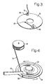
- two terminals 10 and 12 project from what will hereinafter be referred to as the underside of a fusion pad 14.
- An electrically conductive wire 16 which is wound on a reel 18, has one end passed through a hole 20 in the pad 14 and is secured to the terminal 10.
- the wire 16 emerging from the hole 20 is guided into the inner end of a spiral groove 22 which is formed in the upper surface of the pad 14.
- the pad 14 is rotated so as to cause the wire 16 progressively to enter the groove 22.
- the side walls of the groove 22 have a height greater than the diameter of the wire 16 therey ensuring that the groove walls 24 project above the wire 16 in the groove.
- An electrical heating tool 26 is applied to each part of the groove 22 as soon as the wire 16 is located in that groove part thereby causing the adjacent groove walls 24 to heat up and become molten at their upper regions.
- the fusion pad 14 is then located on the forming surface of a tool base 30, and a punch 32 is pressed onto the tool base 30 to shape the pad 14 into the required curvature as illustrated in Figure 7. Because of the previously described technique of retaining the wire 16 in the groove 22, this curving of the pad 14 does not cause the wire 16 to come out of the groove 22.
- the curved shaped pad 14 is connected to a tubular body, such as the previously described body 6, to form a tapping saddle.
- the pad 14 In operation the pad 14 is placed against an appropriate region of a pipe wall, an electrical heating source is connected to the teminals 10 and 12, and the heating coil formed by the wire 16 is heated to fuse the pad 14 to the contacting region of the pipe wall.
- the power source is disconnected from the terminals 10 and 12, and the tapping saddle is secured to the pipe wall ready for use.
- thermoplastics are suitable for producing the pad 14; one example of a suitable thermoplastics is medium or high density polyethylene.
- the illustrated described pad 14 has a thickness in the range from 0.5 mm to 2.0 mm in order to keep the wire 16 close to the adjoining faces of the pad 14 and the pipe.
- a wire 16 having a diameter in the range from 0.4 mm to 2.0 mm is suitable to provide a good joint for pipes having diameters from 15 mm to in excess of 500 mm.
- the type of wire 16 suitable will depend on the heat required for providing different sizes of joints.
- the pad 14, and the body 6, and the pipe wall are all made of the same family of thermoplastics material, such as for example polyethylene.
- the height of the groove side walls 24 above the wire 16 should be in the range from 15% to 50% of the wire diameter and will depend on the width of the thermoplastics material between adjacent turns of the wire 16.
- the spacing between adjacent turns of the wire 16 is arrived at as a result of laboratory and quality assurance tests until the required operational performance is achieved.
- the width of the groove 22 can be in the range from the diameter of the wire 16 to the wire diameter plus approximately 10%.
- the wire when winding the wire 16 into the groove 22, the wire may be held in place in the groove 22 by the top plate of a wire placement jig until the groove 22 is filled with the wire. The upper part of the groove walls 24 are then heated to trap the wire 16 in the groove 22 prior to removing the pad 15 from the jig.
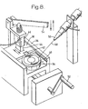
- a wire placement and sealing apparatus includes a turn table 34 which is rotatably mounted on a support structure 36.
- a guide plate 38 is slidably mounted in grooves 40 in the upper region of the support structure 36.
- a slot 42 is formed in the guide plate 38 to extend along a radius of the turn table 34.
- a heating tool 44 is adjustably mounted in the guide plate 38; this heating tool 44 being heated by an electrical heater band 46.
- wire 48 is fed from a nozzle 50 through the hole 20 in the fusion pad 14 and attached to the terminal 10 on the underside of the pad 14.
- the pad 14 is then loaded onto the turn table 34 with the groove 22 upper most.
- the guide plate 38 is slid forward so that the slot 42 lies over the groove 22, and the wire 48 is arranged to pass through the slot 42.
- the slot 42 is sufficiently long to allow the wire 48 to enter the entire range of the groove 22.
- the turn table 34 is rotated by turning a handle 52 thereby causing the wire 48 progressively to enter the spiral groove 22 until the wire reaches the outer end of the spiral groove 22.
- the wire 48 is then cut to length, fed through the notch 28 and secured to the terminal 12.
- the wire 48 is retained in the groove 22 by the guide plate 38; the lower surface of the guide plate 38 just clearing the top of the groove walls 24.
- the guide plate 38 is slid forwardly to locate the heating tool 44 over the groove 22.
- the heating tool 44 extends radially over the turn table 34, and is sufficiently long to embrace the entire radial range of the spiral groove 22.
- the heater band 46 is energised to heat the heating tool 4 which is then lowered by the arm 54to contact and heat up the top of the groove walls 24. Because of the heating action of the heating tool 44 the groove walls become molten at their upper region.
- the turn table 34 is again rotated by the handle 52, and the consequent wiping action of the heating tool 44 spreads the molten upper regions of the groove walls 24 over the wire 48 in the groove 22. When the heating tool 44 has wiped the entire length of the groove 22, the heating tool 44 is withdrawn from contact with the groove walls 24.
- the collapsed wiped upper regions of the groove walls 24 then solidify in that position so as to retain the wire 48 in the groove 22.
- the guide plate 38 is then slid clear of the turn table 34, and the pad 14 is removed in preparation for location on the forming surface of the tool base 30.
- the upper surface of the collapsed and solidified groove walls 24 will be above the upper surface of that part of the fusion pad 14 outside the spiral groove 22. These two levels meet at a ridge 56 illustrated in Figure 4.
- the described and illustrated technique of using a fusion pad is found to be less expensive than the previously known technique of using full wrap round of the pipe.
- This full wrap round involves the use of the two semi-circular pads or clips which fit round opposite portions of the pipe.
- Each clip has two opposite outwardly extending ears, and the facing ears of opposite clips are bolted together so that the two clips extend completely round the pipe.
- the clips are held together by bolts, and the electrical heating of the clip or pad onto the pipe is sufficiently strong only to seal in the contents of the pipe.
- the width of the groove walls 24 is equal to the diameter of the wire 16, and this ratio is altered only when necessary.
- the spacing between adjacentturns of the wire 16 is arrived at as a result of laboratory and quality assurance tests until the required operational performance is achieved.
- the pad 14 has been described as having a thickness in the range from 0.5 mm to 2.0 mm it is the intention to reduce the pad thickness to a minimum. In consequence a pad thickness of 0.2 mm or less is envisaged.
Landscapes
- Engineering & Computer Science (AREA)
- General Engineering & Computer Science (AREA)
- Mechanical Engineering (AREA)
- Chemical & Material Sciences (AREA)
- Composite Materials (AREA)
- Lining Or Joining Of Plastics Or The Like (AREA)
- Branch Pipes, Bends, And The Like (AREA)
Claims (12)
Applications Claiming Priority (2)
| Application Number | Priority Date | Filing Date | Title |
|---|---|---|---|
| GB8410765 | 1984-04-27 | ||
| GB8410765A GB8410765D0 (en) | 1984-04-27 | 1984-04-27 | Fusion pad |
Publications (3)
| Publication Number | Publication Date |
|---|---|
| EP0160536A2 EP0160536A2 (fr) | 1985-11-06 |
| EP0160536A3 EP0160536A3 (en) | 1986-09-10 |
| EP0160536B1 true EP0160536B1 (fr) | 1990-07-04 |
Family
ID=10560163
Family Applications (1)
| Application Number | Title | Priority Date | Filing Date |
|---|---|---|---|
| EP19850302957 Expired - Lifetime EP0160536B1 (fr) | 1984-04-27 | 1985-04-26 | Elément de soudage |
Country Status (8)
| Country | Link |
|---|---|
| US (1) | US4684428A (fr) |
| EP (1) | EP0160536B1 (fr) |
| JP (1) | JPS6116838A (fr) |
| AU (1) | AU580048B2 (fr) |
| CA (1) | CA1242399A (fr) |
| DE (1) | DE3578517D1 (fr) |
| DK (1) | DK183885A (fr) |
| GB (2) | GB8410765D0 (fr) |
Cited By (1)
| Publication number | Priority date | Publication date | Assignee | Title |
|---|---|---|---|---|
| DE4405200C1 (de) * | 1994-02-18 | 1995-06-22 | Sommer Bernd | Verfahren und Vorrichtung zur Herstellung eines Verbindungsformstückes, insbesondere eines Anbohrsattelstückes für Rohrleitungen aus Kunststoff, mit einem Kunststoffschweißelement |
Families Citing this family (16)
| Publication number | Priority date | Publication date | Assignee | Title |
|---|---|---|---|---|
| US5104468A (en) * | 1984-11-13 | 1992-04-14 | Riesselmann & Sohn | Method of producing a molded connection piece and method for joining tube with molded connection piece |
| NL8403462A (nl) * | 1984-11-13 | 1986-06-02 | Arie De Jong | Werkwijze voor het vervaardigen van een verbindingsvormstuk, in het bijzonder aanboorzadel en een volgens de werkwijze vervaardigd verbindingsvormstuk. |
| GB8603979D0 (en) * | 1986-02-18 | 1986-03-26 | Alh Syst Ltd | Addition of branch member to thermoplastic pipes |
| GB8606790D0 (en) * | 1986-03-19 | 1986-04-23 | Glynwed Tubes & Fittings | Thermoplastics member |
| DE3611192A1 (de) * | 1986-04-04 | 1987-10-15 | Riesselmann & Sohn | Verfahren zum verschweissen stumpfgestossener rohre aus kunststoff und schweisselement zur durchfuehrung des verfahrens |
| FR2690036B1 (fr) * | 1992-04-10 | 1998-10-09 | Gaz De France | Filet formant resistance, son application au soudage de tubes aboutes et au raccordement transversal de canalisations, ensembles ainsi constitues et prise de branchement electrosoudable ainsi equipee. |
| US5708251A (en) * | 1995-10-30 | 1998-01-13 | Compucraft Ltd. | Method for embedding resistance heating wire in an electrofusion saddle coupler |
| NL1014620C2 (nl) * | 2000-03-13 | 2001-09-14 | Inventum B V | Verwarmingselement en werkwijze voor het vervaardigen daarvan. |
| KR100487881B1 (ko) * | 2001-12-12 | 2005-05-03 | 동도기공 주식회사 | 노후 보수관의 가지관용 라이닝 장치 |
| US20050184511A1 (en) * | 2004-02-20 | 2005-08-25 | Nelson Irrigation Corporation | Water supply tube and riser assembly and related method |
| US20080001394A1 (en) * | 2006-06-30 | 2008-01-03 | Orion Enterprises, Inc. | Electrofusion saddle wye |
| CN102937221B (zh) * | 2012-11-28 | 2017-06-16 | 薛克强 | 一种ppr管的支路管道连接方法及装置 |
| ES2669743T3 (es) | 2014-01-30 | 2018-05-29 | Plasson Ltd | Elemento de acoplamiento por electrofusión y proceso de fabricación de elemento de acoplamiento por electrofusión |
| US20150210823A1 (en) | 2014-01-30 | 2015-07-30 | Plasson Ltd. | Electrofusion coupler composition |
| CH712996A1 (de) | 2016-09-30 | 2018-04-13 | Hoffmann Neopac Ag | Tube und Tubenkörper mit einer elektronischen Vorrichtung. |
| US11648741B2 (en) * | 2020-05-19 | 2023-05-16 | The Boeing Company | Methods of embedding an elongate susceptor within a thermoplastic body |
Family Cites Families (15)
| Publication number | Priority date | Publication date | Assignee | Title |
|---|---|---|---|---|
| US3378672A (en) * | 1966-03-18 | 1968-04-16 | Susquehanna Corp | Insulated, electrical resistance wire and welding sleeve made therefrom |
| CH544906A (de) * | 1971-11-12 | 1974-01-15 | Gerbert & Cie | Elektrisch heizbare Schweissmuffe und Verfahren zu deren Herstellung |
| NL175458C (nl) * | 1973-03-14 | 1984-11-01 | Sturm Werner | Werkwijze voor het vervaardigen van een lasmof voor thermoplastische buizen. |
| NL181415C (nl) * | 1975-02-21 | 1987-08-17 | Draka Polva Bv | Werkwijze en inrichting voor het vervaardigen van een kunststofonderdeel met een weerstandselement. |
| CH606895A5 (fr) * | 1975-12-18 | 1978-11-15 | Geberit Ag | |
| FR2353381A1 (fr) * | 1976-06-03 | 1977-12-30 | Pont A Mousson | Procede d'assemblage par soudure de tubes plastiques et raccord pour un tel assemblage |
| DE2801604C3 (de) * | 1978-01-14 | 1980-10-02 | Breco Kunststoffverarbeitungs-Gmbh & Co Kg, 4952 Porta Westfalica | Verfahren zur Herstellung eines armierten endlosen Zahnriemens mit Gewebeauflage |
| AU537553B2 (en) * | 1980-08-22 | 1984-06-28 | Industrial Pipe Systems Pty Limited | Electric fusion pipe fittings |
| JPS6142160B2 (fr) * | 1980-08-22 | 1986-09-19 | Esudan Pty Ltd | |
| CH648393A5 (de) * | 1980-08-29 | 1985-03-15 | Werner Sturm | Elektro-schweissmuffe aus einem thermoplast zum verbinden von leitungselementen aus thermoplast. |
| FR2519578A1 (fr) * | 1981-07-01 | 1983-07-18 | Sam Innovation Tech | Dispositif en matiere plastique pour realiser une perforation dans un element sous-jacent en matiere plastique, procede de fabrication d'un tel dispositif et sa mise en oeuvre pour realiser des derivations de canalisations |
| FR2516439A1 (fr) * | 1981-11-13 | 1983-05-20 | Armosig | Procede de soudage electrique de pieces en matiere plastique, en particulier pour canalisations de fluides et manchons de raccordement pour de telles canalisations |
| DE3204681C2 (de) * | 1982-02-11 | 1986-02-06 | Friedrichsfeld Gmbh, Steinzeug- Und Kunststoffwerke, 6800 Mannheim | Verfahren und Vorrichtung zum Einbetten eines elektrischen Heizdrahtes in einem muffenartigen Kunststoffteil |
| US4626308A (en) * | 1983-02-18 | 1986-12-02 | The Victaulic Company Plc | Method of making welded pipe joints |
| AU569278B2 (en) * | 1983-03-09 | 1988-01-28 | Rutland Plastics Ltd. | Weldable thermoplastic pipe fitting |
-
1984
- 1984-04-27 GB GB8410765A patent/GB8410765D0/en active Pending
-
1985
- 1985-04-22 AU AU41480/85A patent/AU580048B2/en not_active Ceased
- 1985-04-24 DK DK183885A patent/DK183885A/da unknown
- 1985-04-26 EP EP19850302957 patent/EP0160536B1/fr not_active Expired - Lifetime
- 1985-04-26 DE DE8585302957T patent/DE3578517D1/de not_active Expired - Fee Related
- 1985-04-26 CA CA000480160A patent/CA1242399A/fr not_active Expired
- 1985-04-26 GB GB8510708A patent/GB2158007B/en not_active Expired
- 1985-04-27 JP JP60089958A patent/JPS6116838A/ja active Pending
-
1986
- 1986-01-28 US US06/823,819 patent/US4684428A/en not_active Expired - Fee Related
Cited By (1)
| Publication number | Priority date | Publication date | Assignee | Title |
|---|---|---|---|---|
| DE4405200C1 (de) * | 1994-02-18 | 1995-06-22 | Sommer Bernd | Verfahren und Vorrichtung zur Herstellung eines Verbindungsformstückes, insbesondere eines Anbohrsattelstückes für Rohrleitungen aus Kunststoff, mit einem Kunststoffschweißelement |
Also Published As
| Publication number | Publication date |
|---|---|
| CA1242399A (fr) | 1988-09-27 |
| DE3578517D1 (de) | 1990-08-09 |
| GB2158007A (en) | 1985-11-06 |
| GB8410765D0 (en) | 1984-06-06 |
| DK183885A (da) | 1985-10-28 |
| AU4148085A (en) | 1985-10-31 |
| DK183885D0 (da) | 1985-04-24 |
| AU580048B2 (en) | 1988-12-22 |
| US4684428A (en) | 1987-08-04 |
| JPS6116838A (ja) | 1986-01-24 |
| GB2158007B (en) | 1987-06-10 |
| EP0160536A2 (fr) | 1985-11-06 |
| GB8510708D0 (en) | 1985-06-05 |
| EP0160536A3 (en) | 1986-09-10 |
Similar Documents
| Publication | Publication Date | Title |
|---|---|---|
| EP0160536B1 (fr) | Elément de soudage | |
| CA1178883A (fr) | Dispositif en matiere plastique pour pratiquer une ouverture dans element plastique sous-jacent, methode de production dudit dispositif, et son emploi dans le piquage sur canalisation | |
| CA1210925A (fr) | Methode de raccordement de canalisations venues de fabrication avec un revetement thermofuge, et raccord a souder connexe | |
| US4894521A (en) | Electric heating element for fusing thermoplastic materials | |
| US5096632A (en) | Method of manufacturing an electrofusion coupler | |
| EP0258827B1 (fr) | Méthode pour assemblage d'un bout de tuyau plastique avec un manchon plastique soudable | |
| EP0058175B1 (fr) | Raccordements de tubes par fusion electrique | |
| US5238615A (en) | Method for joining together of tubular plastic products | |
| US4806181A (en) | Method for moulding a thermoplastics member with a fusion pad | |
| JPH0739120B2 (ja) | 溶着継手の製造方法 | |
| EP0119061A1 (fr) | Pièces de raccordement de tuyaux soudables | |
| JPH08244116A (ja) | 波形管の溶着方法及び溶着装置 | |
| EP2317203B1 (fr) | Procédé de revêtement d'un raccord de deux tuyaux | |
| US20030214131A1 (en) | Coupling-equipped pipe and apparatus for manufacturing the same | |
| JPH06213387A (ja) | ポリオレフィンパイプの接合方法およびこれに用いる金属製インコア | |
| JPS62292419A (ja) | 熱絶縁された導管のためのソケツト結合部を製造する際の熔接工程の制御方法と装置 | |
| GB2136074A (en) | Weldable Pipe Fittings | |
| JPH1113980A (ja) | 合成樹脂管用継手 | |
| CA1217913A (fr) | Methode de thermofugation des piquages et raccords de tuyauteries | |
| JPH05244713A (ja) | ケーブル補修方法 | |
| GB1579196A (en) | Forming sheathed jointed cables | |
| AU537553B2 (en) | Electric fusion pipe fittings | |
| JP3636354B2 (ja) | 電気融着式プラスチック管継手 | |
| JPS61272130A (ja) | プラスチツク管の接合方法 | |
| JP3764522B2 (ja) | エレクトロフュージョン継手とその製造法 |
Legal Events
| Date | Code | Title | Description |
|---|---|---|---|
| PUAI | Public reference made under article 153(3) epc to a published international application that has entered the european phase |
Free format text: ORIGINAL CODE: 0009012 |
|
| AK | Designated contracting states |
Designated state(s): BE DE FR IT NL |
|
| PUAL | Search report despatched |
Free format text: ORIGINAL CODE: 0009013 |
|
| AK | Designated contracting states |
Kind code of ref document: A3 Designated state(s): BE DE FR IT NL |
|
| 17P | Request for examination filed |
Effective date: 19861029 |
|
| 17Q | First examination report despatched |
Effective date: 19880210 |
|
| GRAA | (expected) grant |
Free format text: ORIGINAL CODE: 0009210 |
|
| AK | Designated contracting states |
Kind code of ref document: B1 Designated state(s): BE DE FR IT NL |
|
| REF | Corresponds to: |
Ref document number: 3578517 Country of ref document: DE Date of ref document: 19900809 |
|
| ET | Fr: translation filed | ||
| ITF | It: translation for a ep patent filed | ||
| PG25 | Lapsed in a contracting state [announced via postgrant information from national office to epo] |
Ref country code: BE Effective date: 19910430 |
|
| PLBE | No opposition filed within time limit |
Free format text: ORIGINAL CODE: 0009261 |
|
| STAA | Information on the status of an ep patent application or granted ep patent |
Free format text: STATUS: NO OPPOSITION FILED WITHIN TIME LIMIT |
|
| 26N | No opposition filed | ||
| BERE | Be: lapsed |
Owner name: GLYNWED TUBES & FITTINGS LTD Effective date: 19910430 |
|
| PG25 | Lapsed in a contracting state [announced via postgrant information from national office to epo] |
Ref country code: NL Effective date: 19911101 |
|
| NLV4 | Nl: lapsed or anulled due to non-payment of the annual fee | ||
| PG25 | Lapsed in a contracting state [announced via postgrant information from national office to epo] |
Ref country code: FR Effective date: 19911230 |
|
| PG25 | Lapsed in a contracting state [announced via postgrant information from national office to epo] |
Ref country code: DE Effective date: 19920201 |
|
| REG | Reference to a national code |
Ref country code: FR Ref legal event code: ST |