EP0160542A2 - Kühlmittelverteiler und Verfahren zur Einrichtung eines solchen Verteilers - Google Patents
Kühlmittelverteiler und Verfahren zur Einrichtung eines solchen Verteilers Download PDFInfo
- Publication number
- EP0160542A2 EP0160542A2 EP85302972A EP85302972A EP0160542A2 EP 0160542 A2 EP0160542 A2 EP 0160542A2 EP 85302972 A EP85302972 A EP 85302972A EP 85302972 A EP85302972 A EP 85302972A EP 0160542 A2 EP0160542 A2 EP 0160542A2
- Authority
- EP
- European Patent Office
- Prior art keywords
- chamber
- refrigerant
- nozzle plate
- distributor
- housing
- Prior art date
- Legal status (The legal status is an assumption and is not a legal conclusion. Google has not performed a legal analysis and makes no representation as to the accuracy of the status listed.)
- Granted
Links
- 239000003507 refrigerant Substances 0.000 title claims abstract description 38
- 238000000034 method Methods 0.000 title claims description 8
- 238000005057 refrigeration Methods 0.000 claims abstract description 10
- 238000011144 upstream manufacturing Methods 0.000 claims description 6
- 239000007788 liquid Substances 0.000 description 5
- 238000011109 contamination Methods 0.000 description 2
- 230000000694 effects Effects 0.000 description 2
- 238000004519 manufacturing process Methods 0.000 description 2
- 239000008240 homogeneous mixture Substances 0.000 description 1
- 239000000203 mixture Substances 0.000 description 1
- 238000005086 pumping Methods 0.000 description 1
- 239000007787 solid Substances 0.000 description 1
Images
Classifications
-
- F—MECHANICAL ENGINEERING; LIGHTING; HEATING; WEAPONS; BLASTING
- F25—REFRIGERATION OR COOLING; COMBINED HEATING AND REFRIGERATION SYSTEMS; HEAT PUMP SYSTEMS; MANUFACTURE OR STORAGE OF ICE; LIQUEFACTION SOLIDIFICATION OF GASES
- F25B—REFRIGERATION MACHINES, PLANTS OR SYSTEMS; COMBINED HEATING AND REFRIGERATION SYSTEMS; HEAT PUMP SYSTEMS
- F25B39/00—Evaporators; Condensers
- F25B39/02—Evaporators
- F25B39/028—Evaporators having distributing means
-
- F—MECHANICAL ENGINEERING; LIGHTING; HEATING; WEAPONS; BLASTING
- F25—REFRIGERATION OR COOLING; COMBINED HEATING AND REFRIGERATION SYSTEMS; HEAT PUMP SYSTEMS; MANUFACTURE OR STORAGE OF ICE; LIQUEFACTION SOLIDIFICATION OF GASES
- F25B—REFRIGERATION MACHINES, PLANTS OR SYSTEMS; COMBINED HEATING AND REFRIGERATION SYSTEMS; HEAT PUMP SYSTEMS
- F25B41/00—Fluid-circulation arrangements
- F25B41/40—Fluid line arrangements
- F25B41/42—Arrangements for diverging or converging flows, e.g. branch lines or junctions
- F25B41/45—Arrangements for diverging or converging flows, e.g. branch lines or junctions for flow control on the upstream side of the diverging point, e.g. with spiral structure for generating turbulence
Definitions
- This invention relates to a distributor used to feed refrigerant to the component circuits of a multi- circuit evaporator in a direct expansion refrigeration system, and to a method of setting-up such a distributor.
- the universal method used to distribute the refrigerant in a direct expansion evaporator coil to each individual circuit is through small diameter feeder pipes connected together in an accurately machined cone-shaped header so that each pipe is aligned with its neighbour in both position and angle.
- the cone-shaped header is located downstream of the expansion valve (or other refrigerant metering device) and thus has to divide a mixed liquid/vapour to the separate feeder pipes.
- the size of the feeder pipes does, by creating a' pressure drop, help considerably with the distribution of the refrigerant, due to the application range, type of refrigerant and site conditions which can occur, they can only partly cope.
- devices of United States manufacture have been used to distribute the liquid refrigerant between circuits by employing a nozzle plate removably fitted into a cavity just upstream of a cone-shaped deflector to create a mixing point for the refrigerant just prior to its distribution through the separate distribution feeder pipes.
- nozzle plates are removably mounted in the distributor, they can be changed only with diffi- cultyy because a considerable amount of refrigeration pipework has to be disconnected and the nozzle plate "fished out" from the cavity which is always difficult and in a low temperature cold room rapidly becomes a most unpleasant task.
- the present invention relates inter alia to an improved refrigerant distributor which reduces the severity of some of the problems detailed above.
- a refrigerant distributor comprising a housing defining a refrigerant chamber, an inlet for refrigerant to the chamber and a plurality of outlets for refrigerant from the chamber with a nozzle plate disposed in the chamber is characterised in that the housing includes a nozzle plate removing passage opening into the chamber and seal means for closing said passage.
- the chamber is large enough to accommodate two nozzle plates, a first in the flowpath of refrigerant from the inlet to the outlets and a second, linked to the first, adjacent to the location where the nozzle plate removing passage opens into the chamber.
- the second nozzle plate can be provided with a pilot recess or hole of smaller bore than that in the first nozzle plate so that it can be drilled out as required following removal from the housing.
- the linkage between, the first and second nozzle plates includes a measure of resilience.
- the housing also includes a pressure measuring point which opens into the chamber upstream of the nozzle plate.
- the first nozzle plate would be located just upstream of a cone-shaped deflector around which are arranged the refrigerant outlets.
- the tried and proven nozzle type distribution system is used but with the advantage that the nozzle plate is more accessible and consequently it is quicker for an installer of a refrigerating system to change it.
- Charts would-be provided with- each distributor so that predicted nozzle bores could be determined after running the refrigeration system at or close to its operating conditions with the "standard” or first nozzle plate in place in the housing.
- the predicted nozzle size can be expected to be determined in one operation, thus making just one opening of the chamber for nozzle plate removal necessary.
- Another aspect of the invention represents an improved method of setting-up a refrigeration plant using a distributor as defined above and this is featured in the following claim 8.
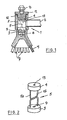
- the distributor shown in Figure 1 has a housing 1 defining a chamber 2 that contains a pair of nozzle plates 3 and 4 linked by a linkage generally shown at 5.
- a refrigerant inlet 6 and a plurality of outlets 7 are provided in the usual manner.
- a conical deflector 8 is provided centrally below the bore 9 in the plate 3.
- a pressure-sensing connection '10 is provided in the housing 1 as is a plug 11 closing a passage 12 large enough to permit removal of the linked plates 3, 4.
- the plate 4 can have a pilot hole 13 in it so that following removal from the housing 1 it can be drilled out easily to the required bore size.
- the pressure sensing connection 10 has been shown in the upper surface of the plug 11 since this is advantageous having regard to manufacturing cost and accessibility for connection to a pressure gauge. However the connection 10 could be located elsewhere, for example in the wall of the housing 1.
- the pressure sensing connection 10 may be a simple flare connection or it could be a Schroeder valve to facilitate the connection of a pressure valve thereto.
- the linkage 5 can be rods 5a, 5b as shown in Figure 2 which spring load the plates 3, 4 away from each other and aid in retaining the operating nozzle plate 3 in its correct position relative to the conical deflector 8.
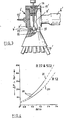
- FIG 3 shows a modified arrangement in which the same reference numerals have been used as were used in Figure 1 but with the addition of a prime.
- the chamber 2' includes a nozzle plate 3' and the housing 1' includes a valve 13 attached to a spindle 14 which is threadedly engaged in the plug 11'.
- the valve 13 includes a spigot 15 sliding in a recess 16 to keep the valve 13 central in the aperture 9' in the nozzle plate 3'.
- a further possibility is the use of a spring-loaded nozzle with a guide, so that on reverse refrigerant flow conditions (e.g. a reverse cycle defrost) the liquid refrigerant will lift the nozzle and bypass this liquid around the nozzle hole rather than through it to reduce the pressure losses.
- reverse refrigerant flow conditions e.g. a reverse cycle defrost
- This arrangement could improve the effectiveness and efficiency of the reverse cycle defrost.
- the nozzle Upon restoration of the normal refrigeration effect the nozzle would return to its seat under the action of the spring and guide.
- the pressure drop occurring across the distributor needs to be measured during normal operation of the system. This can be assessed with sufficient accuracy by pumping the system down to atmospheric pressure and fitting a suitable pressure gauge to the connection 10. On restarting the system, the difference in pressure ( ⁇ P) between that indicated on the gauge and the suction pressure of the system is noted.
- a ratio can be read off that corresponds to the measured ⁇ P.
- This ratio indicates the change required in the diameter of the hole 9.
- the measured ⁇ Pindicated a ratio of 1.25 and the hole has a diameter of 10 mm
- the likely new hole diameter would be 12.5 mm and a reboring to at least 12 mm should be made before the ⁇ P is remeasured.
- the hole 9 can easily be bored out further, but if the ratio is less than unity, a new nozzle plate with a smaller hole (e.g. plate 4) must be used for the reboring operation.
- the pressure gauge can be connected to the connection 10' and the spindle 14 adjusted to bring the 4P down to the value shown by the respective normal point 22.
Landscapes
- Engineering & Computer Science (AREA)
- Physics & Mathematics (AREA)
- Mechanical Engineering (AREA)
- Thermal Sciences (AREA)
- General Engineering & Computer Science (AREA)
- Filling Or Discharging Of Gas Storage Vessels (AREA)
Applications Claiming Priority (2)
| Application Number | Priority Date | Filing Date | Title |
|---|---|---|---|
| GB848410844A GB8410844D0 (en) | 1984-04-27 | 1984-04-27 | Refrigerant distributors |
| GB8410844 | 1984-04-27 |
Publications (3)
| Publication Number | Publication Date |
|---|---|
| EP0160542A2 true EP0160542A2 (de) | 1985-11-06 |
| EP0160542A3 EP0160542A3 (en) | 1986-09-03 |
| EP0160542B1 EP0160542B1 (de) | 1989-12-20 |
Family
ID=10560190
Family Applications (1)
| Application Number | Title | Priority Date | Filing Date |
|---|---|---|---|
| EP85302972A Expired EP0160542B1 (de) | 1984-04-27 | 1985-04-26 | Kühlmittelverteiler und Verfahren zur Einrichtung eines solchen Verteilers |
Country Status (3)
| Country | Link |
|---|---|
| EP (1) | EP0160542B1 (de) |
| DE (1) | DE3574905D1 (de) |
| GB (1) | GB8410844D0 (de) |
Families Citing this family (1)
| Publication number | Priority date | Publication date | Assignee | Title |
|---|---|---|---|---|
| CN119063565B (zh) * | 2024-11-07 | 2025-01-28 | 中国核动力研究设计院 | 一种基于ai的旋叶式流量自分配封头及其自动调控方法 |
Family Cites Families (7)
| Publication number | Priority date | Publication date | Assignee | Title |
|---|---|---|---|---|
| US2044455A (en) * | 1935-05-16 | 1936-06-16 | Young Radiator Co | Distributing head for evaporators |
| US2126364A (en) * | 1937-07-14 | 1938-08-09 | Young Radiator Co | Evaporator distributor head |
| US2960845A (en) * | 1958-01-31 | 1960-11-22 | Sporlan Valve Co | Refrigerant control for systems with variable head pressure |
| US3563055A (en) * | 1969-03-17 | 1971-02-16 | Sporlan Valve Co | Refrrigerant distribvtor |
| US3741242A (en) * | 1971-12-10 | 1973-06-26 | Refrigerating Specialties Co | Refrigerant feed control and system |
| US3864938A (en) * | 1973-09-25 | 1975-02-11 | Carrier Corp | Refrigerant flow control device |
| ES512122A0 (es) * | 1981-07-08 | 1983-02-16 | Sueddeutsche Kuehler Behr | "perfeccionamientos en los evaporadores". |
-
1984
- 1984-04-27 GB GB848410844A patent/GB8410844D0/en active Pending
-
1985
- 1985-04-26 EP EP85302972A patent/EP0160542B1/de not_active Expired
- 1985-04-26 DE DE8585302972T patent/DE3574905D1/de not_active Expired - Fee Related
Also Published As
| Publication number | Publication date |
|---|---|
| GB8410844D0 (en) | 1984-06-06 |
| EP0160542A3 (en) | 1986-09-03 |
| EP0160542B1 (de) | 1989-12-20 |
| DE3574905D1 (de) | 1990-01-25 |
Similar Documents
| Publication | Publication Date | Title |
|---|---|---|
| US2707868A (en) | Refrigerating system, including a mixing valve | |
| US3741242A (en) | Refrigerant feed control and system | |
| US3563055A (en) | Refrrigerant distribvtor | |
| US4589263A (en) | Multiple compressor oil system | |
| US4184341A (en) | Suction pressure control system | |
| DE69327385T2 (de) | Klimaanlage | |
| US5004008A (en) | Variable area refrigerant expansion device | |
| US2385667A (en) | Refrigerating system | |
| US7841208B2 (en) | Method and system for improving the efficiency of a refrigeration system | |
| EP0439992B1 (de) | Kältemittel-Entspannungsvorrichtung mit veränderlichem Querschnitt | |
| US4418548A (en) | Variable capacity multiple compressor refrigeration system | |
| DE60031565T2 (de) | Dampfkompressionssystem und verfahren zur steuerung der umgebungsverhältnisse | |
| US2148413A (en) | Refrigerating apparatus | |
| US3642030A (en) | Refrigerant throttling device | |
| US2568123A (en) | Pressure reducing device for refrigerating apparatus | |
| EP0152234A2 (de) | Mehrstufige Einrichtung zur Kondensatentfernung aus einem Dampfrohrsystem | |
| US2063380A (en) | Refrigerant distributor | |
| US4503685A (en) | Oil control valve for refrigeration system | |
| US10845106B2 (en) | Accumulator and oil separator | |
| US4612783A (en) | Selectively variable flowrate expansion apparatus | |
| US2168404A (en) | Refrigerant distribution | |
| US3919858A (en) | Direct liquid refrigerant supply and return system | |
| US3449923A (en) | Refrigerant feed control and systems | |
| US2461876A (en) | Liquid distributor for refrigerating systms | |
| EP1128137A1 (de) | Wärmepumpe |
Legal Events
| Date | Code | Title | Description |
|---|---|---|---|
| PUAI | Public reference made under article 153(3) epc to a published international application that has entered the european phase |
Free format text: ORIGINAL CODE: 0009012 |
|
| AK | Designated contracting states |
Designated state(s): BE DE FR GB IT NL SE |
|
| PUAL | Search report despatched |
Free format text: ORIGINAL CODE: 0009013 |
|
| AK | Designated contracting states |
Kind code of ref document: A3 Designated state(s): BE DE FR GB IT NL SE |
|
| 17P | Request for examination filed |
Effective date: 19861101 |
|
| 17Q | First examination report despatched |
Effective date: 19870508 |
|
| GRAA | (expected) grant |
Free format text: ORIGINAL CODE: 0009210 |
|
| AK | Designated contracting states |
Kind code of ref document: B1 Designated state(s): BE DE FR GB IT NL SE |
|
| PG25 | Lapsed in a contracting state [announced via postgrant information from national office to epo] |
Ref country code: SE Effective date: 19891220 |
|
| REF | Corresponds to: |
Ref document number: 3574905 Country of ref document: DE Date of ref document: 19900125 |
|
| ITF | It: translation for a ep patent filed | ||
| ET | Fr: translation filed | ||
| PLBE | No opposition filed within time limit |
Free format text: ORIGINAL CODE: 0009261 |
|
| STAA | Information on the status of an ep patent application or granted ep patent |
Free format text: STATUS: NO OPPOSITION FILED WITHIN TIME LIMIT |
|
| 26N | No opposition filed | ||
| ITTA | It: last paid annual fee | ||
| PGFP | Annual fee paid to national office [announced via postgrant information from national office to epo] |
Ref country code: GB Payment date: 19940218 Year of fee payment: 10 |
|
| PGFP | Annual fee paid to national office [announced via postgrant information from national office to epo] |
Ref country code: BE Payment date: 19940301 Year of fee payment: 10 |
|
| PGFP | Annual fee paid to national office [announced via postgrant information from national office to epo] |
Ref country code: FR Payment date: 19940418 Year of fee payment: 10 |
|
| PGFP | Annual fee paid to national office [announced via postgrant information from national office to epo] |
Ref country code: NL Payment date: 19940430 Year of fee payment: 10 |
|
| PGFP | Annual fee paid to national office [announced via postgrant information from national office to epo] |
Ref country code: DE Payment date: 19940629 Year of fee payment: 10 |
|
| PG25 | Lapsed in a contracting state [announced via postgrant information from national office to epo] |
Ref country code: GB Effective date: 19950426 |
|
| PG25 | Lapsed in a contracting state [announced via postgrant information from national office to epo] |
Ref country code: BE Effective date: 19950430 |
|
| BERE | Be: lapsed |
Owner name: SUTER ENVIRONMENTAL LTD Effective date: 19950430 |
|
| PG25 | Lapsed in a contracting state [announced via postgrant information from national office to epo] |
Ref country code: NL Effective date: 19951101 |
|
| GBPC | Gb: european patent ceased through non-payment of renewal fee |
Effective date: 19950426 |
|
| PG25 | Lapsed in a contracting state [announced via postgrant information from national office to epo] |
Ref country code: FR Effective date: 19951229 |
|
| NLV4 | Nl: lapsed or anulled due to non-payment of the annual fee |
Effective date: 19951101 |
|
| PG25 | Lapsed in a contracting state [announced via postgrant information from national office to epo] |
Ref country code: DE Effective date: 19960103 |
|
| REG | Reference to a national code |
Ref country code: FR Ref legal event code: ST |