EP0160587A1 - Frequenzregelung eines Filters mit gyromagnetischen Resonatoren - Google Patents
Frequenzregelung eines Filters mit gyromagnetischen Resonatoren Download PDFInfo
- Publication number
- EP0160587A1 EP0160587A1 EP85400490A EP85400490A EP0160587A1 EP 0160587 A1 EP0160587 A1 EP 0160587A1 EP 85400490 A EP85400490 A EP 85400490A EP 85400490 A EP85400490 A EP 85400490A EP 0160587 A1 EP0160587 A1 EP 0160587A1
- Authority
- EP
- European Patent Office
- Prior art keywords
- magnetic field
- filter
- frequency
- resonators
- signal
- Prior art date
- Legal status (The legal status is an assumption and is not a legal conclusion. Google has not performed a legal analysis and makes no representation as to the accuracy of the status listed.)
- Granted
Links
- 238000001228 spectrum Methods 0.000 claims description 5
- 230000006978 adaptation Effects 0.000 claims 1
- 230000001419 dependent effect Effects 0.000 abstract 1
- 230000008901 benefit Effects 0.000 description 3
- 230000001276 controlling effect Effects 0.000 description 2
- 230000008878 coupling Effects 0.000 description 2
- 238000010168 coupling process Methods 0.000 description 2
- 238000005859 coupling reaction Methods 0.000 description 2
- 239000002223 garnet Substances 0.000 description 2
- 210000000056 organ Anatomy 0.000 description 2
- 229910000859 α-Fe Inorganic materials 0.000 description 2
- 229910052788 barium Inorganic materials 0.000 description 1
- DSAJWYNOEDNPEQ-UHFFFAOYSA-N barium atom Chemical compound [Ba] DSAJWYNOEDNPEQ-UHFFFAOYSA-N 0.000 description 1
- 239000003990 capacitor Substances 0.000 description 1
- 230000003247 decreasing effect Effects 0.000 description 1
- 238000010586 diagram Methods 0.000 description 1
- 230000005670 electromagnetic radiation Effects 0.000 description 1
- 229910052733 gallium Inorganic materials 0.000 description 1
- MTRJKZUDDJZTLA-UHFFFAOYSA-N iron yttrium Chemical compound [Fe].[Y] MTRJKZUDDJZTLA-UHFFFAOYSA-N 0.000 description 1
- JXGGISJJMPYXGJ-UHFFFAOYSA-N lithium;oxido(oxo)iron Chemical compound [Li+].[O-][Fe]=O JXGGISJJMPYXGJ-UHFFFAOYSA-N 0.000 description 1
- 239000000696 magnetic material Substances 0.000 description 1
- 230000010355 oscillation Effects 0.000 description 1
- 230000001105 regulatory effect Effects 0.000 description 1
Images

Classifications
-
- H—ELECTRICITY
- H03—ELECTRONIC CIRCUITRY
- H03J—TUNING RESONANT CIRCUITS; SELECTING RESONANT CIRCUITS
- H03J7/00—Automatic frequency control; Automatic scanning over a band of frequencies
- H03J7/02—Automatic frequency control
- H03J7/04—Automatic frequency control where the frequency control is accomplished by varying the electrical characteristics of a non-mechanically adjustable element or where the nature of the frequency controlling element is not significant
- H03J7/14—Controlling the magnetic state of inductor cores
-
- H—ELECTRICITY
- H01—ELECTRIC ELEMENTS
- H01P—WAVEGUIDES; RESONATORS, LINES, OR OTHER DEVICES OF THE WAVEGUIDE TYPE
- H01P1/00—Auxiliary devices
- H01P1/20—Frequency-selective devices, e.g. filters
- H01P1/215—Frequency-selective devices, e.g. filters using ferromagnetic material
- H01P1/218—Frequency-selective devices, e.g. filters using ferromagnetic material the ferromagnetic material acting as a frequency selective coupling element, e.g. YIG-filters
Definitions
- the present invention relates to a device for controlling the working frequency, associated with a working magnetic field, of a gyromagnetic resonance filter, as a function of a reference frequency to which corresponds, at least theoretically, a field. magnetic reference.
- Gyromagnetic resonance filters use monocrystalline resonators, for example YIG or GaYIG ferrite (yttrium-iron garnet or yttrium-iron-gallium garnet), or lithium ferrite, or barium, placed in the continuous magnetic field of a electro magnet.
- monocrystalline resonators for example YIG or GaYIG ferrite (yttrium-iron garnet or yttrium-iron-gallium garnet), or lithium ferrite, or barium, placed in the continuous magnetic field of a electro magnet.
- Adjusting the intensity of this magnetic field allows you to adjust the working frequency of the filter, which operates as a bandpass. Because of their one-to-one correspondence in the theory of gyromagnetic resonance, the notions of frequency of a signal and intensity of a magnetic field. may moreover be substituted for one another as long as the phenomena concerned are those of gyromagnetic resonance.
- a microwave (RF) input signal applied to one end of an input loop, the other end of which is grounded, excites the resonator.
- the filtered RF output signal is recovered on an output loop of the filter, similar to the input loop but arranged in a plane perpendicular to that which contains the input loop.
- the central working frequency of a filter, and the oscillation frequency of a local oscillator combined with this filter in a spectrum analyzer must be able to be modified together while keeping a constant frequency difference.
- This constraint is the source of difficulties all the more important as the frequency difference to be kept constant is low compared to the working frequency of the filter, as the intensity of the working magnetic field of the filter is not directly known. , but only by the theoretical relation which links it to the intensity of the current supplying the electromagnet which creates this magnetic field, and more different factors, mainly the temperature, are responsible for a certain shift between the real resonant frequency of the filter and the theoretical resonant frequency as predicted by the theoretical relationship which links it to the applied magnetic field.
- the aim of the present invention is to overcome the difficulties mentioned above by proposing a device for controlling the working frequency of a gyromagnetic resonance filter which does not act only as a function of the value of the current d supply of the filter electromagnet, or even function of the value of the magnetic field created by this electromagnet, but directly as a function of this working frequency.
- the device of the invention is essentially characterized in that it comprises a frequency discriminator physically integrated into the filter and subject to the influences prevailing in the latter, this discriminator comprising first and second gyromagnetic resonators subjected not only to the working magnetic field of the filter but also to first and second respective additional local magnetic fields forming, with the working magnetic field of the filter, first and second resulting magnetic fields, the intensities of which are respectively greater and less than that of the reference magnetic field, and in that these resonators are both excited by an electromagnetic signal at the reference frequency, so as to produce, on respective outputs, respective output signals each depending on the amplitude and / or the sign of the imbalance between the field magnetic field to which the resonator concerned and the magnetic field are subjected eu of reference corresponding to the signal at the frequency of reference which this resonator receives, this device comprising slaves receiving these two output signals and acting on the intensity of the working magnetic field of the filter, in a direction suitable for reducing the amplitude and / or change the sign of
- the half-sum of the first and second additional local magnetic fields is fixed at a non-zero value, corresponding to the desired offset between the working frequency of the filter and the reference frequency.
- the servocontrol members comprise first and second detectors connected to the respective outputs of the first and second resonators, and delivering respective output signals, representative of said imbalances, and substantially continuous.
- the outputs of the first and second detectors are for example connected to the inputs of a differential amplifier delivering an error signal whose polarity and amplitude are respectively representative of the sign and of the amplitude of the difference between the value of the actual working frequency of the filter and the value it should have depending on the value of the reference frequency.
- the line leading said signal at the reference frequency to the first and second resonators is common to these two resonators.
- the two additional local magnetic fields are preferably formed by the superposition of a uniform common magnetic field for the two resonators, and of two respective fields of the same intensity and opposite directions, created by a crossed current loop.
- the invention is applicable to spectrum analyzers, in which the operation of the filter is linked to that of a local oscillator. More generally, the invention is applicable to wideband microwave receivers and to all systems using a resonance filter gyromagnetic whose working frequency must be adjusted according to a reference frequency. In most conceivable cases, the signal at the reference frequency used is the output signal from a local oscillator.
- the present invention relates to bandpass filters of the YIG or GaYIG filter type, and the control of their working frequency.
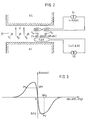
- These filters comprise, in a known manner, at least one, and for example three ferrite resonators Y 1 . Y 2 , Y 3 subjected on the one hand to an adjustable continuous magnetic field H and on the other hand to the electromagnetic radiation of an RF microwave input signal flowing in an input loop BE1, BE2, BE3, surrounding at least partially the resonator and arranged in a plane parallel to the magnetic field H.
- each resonator For each resonator is provided an output loop BS1, BS2, BS3, similar to the input loop but perpendicular to it.
- Each resonator induces in the output loop associated with it an RF output signal located in a band whose central frequency is regulated by the intensity of the H field and whose amplitude depends on the amplitude of the frequency spectrum of the RF input signal in this band.
- the resonators are held by bars of non-magnetic material (not shown) in the air gap EF (fig. 2) of an electromagnet composed of a lower pole AI and an upper pole AS.
- the field H is controlled as a function of the electric current I c supplying this electromagnet.
- Figures 1 and 2 show a filter with three cascaded resonators.
- the output signal of the first two resonators Y 1 , Y 2 constitutes the input signal of the following respective resonators Y 2 , Y 3 , and as shown in FIG. 1, one end of each loop BEI to BE3 and BS1 to BS3 is connected to ground.
- the RF output signal of the filter is for example mixed, in a mixer M, with the output signal OL of a local oscillator, for example a voltage controlled VCO oscillator, in order to produce an intermediate frequency signal FI.
- a local oscillator for example a voltage controlled VCO oscillator
- the frequency of the filtered RF signal can be of the order of a few gigaherz to about twenty gigaherz
- the frequency of the IF signal which is equal to the difference between the frequency of the filtered RF signal and that of the OL reference signal, can be of the order of a few hundred megaherz.
- the device of the invention has the function of adjusting to a desired value, with respect to the frequency of the reference signal OL, the working frequency of the filter.
- this device essentially comprises: two gyromagnetic resonators Y 4 , Y 5 forming part of a frequency discriminator; two detectors DT1, DT2 respectively connected to the output loops BS4, BS5 of the resonators Y 4 , Y 5 ; a differential amplifier A1 receiving the output signals from the detectors; a summing amplifier A2 carrying out the algebraic sum of the output signal of the differential amplifier and of an adjustment voltage V H : and a voltage-current converter CTC supplied by the summing amplifier A2 and producing the supply current 1 of the electromagnet of the filter.
- the resonators Y 4 , Y 5 receive on their respective input loops BE4, BE5, the local oscillator signal OL, taken as frequency reference.
- resonators Y 4 , Y 5 are, like the filter resonators, arranged in the air gap of the electromagnet of the filter and are therefore subject to the working magnetic field H of the filter, as well as to all the influences to which are also subject the resonators Y 1 , Y 2 , Y 3 .
- the resonators Y 4 , Y 5 of the frequency discriminator are further subjected to additional local magnetic fields, of respective intensities ⁇ H + ⁇ h and ⁇ H - ⁇ h, forming, with the working field H of the filter, of the respective resulting fields of intensities H + ⁇ H + ⁇ h and H + ⁇ H - ⁇ h.
- the additional local fields ⁇ H + ⁇ h and ⁇ H - ⁇ h are formed by the superposition of a magnetic field ⁇ H common to the two resonators and of two magnetic fields ⁇ h and - ⁇ h of the same intensity but in opposite directions.
- the common local field ⁇ H is produced by a current loop, with one or more turns, arranged in the air gap EF of the electromagnet of the filter near the resonators Y 4 , Y 5 , and supplied by a current source continuous SI delivering a current of intensity I.
- the contrary local fields ⁇ h and - ⁇ h are produced by a crossed current loop, with one or more turns, also arranged in the air gap EF of the electromagnet near the resonators.
- the current loop is crossed between the two resonators, and supplied by a direct current source Si delivering a current of intensity i.
- the chapters ⁇ H and ⁇ h have relatively low values and correspond, for example, respectively to frequencies of a few hundred and a few tens of megaherz. Because of these low values, the theoretical correspondence between the intensity of the additional local fields ⁇ H + ⁇ h and ⁇ H - ⁇ h and the resonant frequency shifts ⁇ F + ⁇ f and ⁇ F - ⁇ f which they introduce for the resonators Y4 and Y5 is assumed to be verified.
- the resonator Y 4 which is subjected to a resulting field H + ⁇ H + ⁇ h, in which the local additional field ⁇ h partially or totally compensates for the weakness of the field H, transmits on its output loop BS4 more energy than does not transmit, on the loop BS5, the resonator Y S which is subjected to a resulting field H + ⁇ H - ⁇ h, weaker still than the field H + ⁇ H
- Detectors DT1 and DT2 whose function is essentially only to transform into continuous signals the output signals of the resonators Y 4 and Y 5 , deliver signals which are the images of the output levels of the resonators Y 4 and Y 5 .
- the level of the output signal of the differential amplifier Al representative of the difference between the output signals of the detectors DT1 and DT2 is for example represented by the point Pl of the curve of FIG. 3, whose ordinate is DP1.
- the current voltage converter CTC which produces for example a current increasing with the control voltage which it receives, is controlled by a voltage V H + DP1, and therefore produces a corrected current I c of greater intensity than if it was controlled by the voltage V H alone .
- the magnetic field H is thus corrected so as to bring point P 1 closer to the point of origin 0.
- the output signal of the detector DT2 would have had a level higher than that of DT1 detector output signal.
- the differential amplifier A1 would thus have delivered a negative signal of amplitude DP2 and the control voltage of the converter CTC would have decreased, resulting in a reduction of the error affecting the intensity of the magnetic field H.
- the detectors DTI, DT2, the differential amplifier Al, the summing amplifier A2 and the converter CTC thus achieve a control of the magnetic field H in a direction suitable for reducing the difference between the mean field H + AH to which the resonators Y are subjected. 4 , Y 5 , and the field H o corresponding to the reference frequency Fo of the signal OL taken as reference.
- the detectors DT1, DT2 are for example known detectors each comprising an input capacitance C1, C2, in series with an output diode DD1, DD2, the point common to the input capacitance and to the output diode being connected at the ground through an inductor L1, L2, and the output terminal of the detector being itself connected to ground through a second capacitor K1, K2.
- the reference signal OL is applied directly, by a common line LC, to the input loops BE4 and BE5 of the resonators Y 4 8 Y 5 .
Landscapes
- Engineering & Computer Science (AREA)
- Power Engineering (AREA)
- Control Of Motors That Do Not Use Commutators (AREA)
- Gyroscopes (AREA)
- Navigation (AREA)
- Oscillators With Electromechanical Resonators (AREA)
- Networks Using Active Elements (AREA)
Priority Applications (1)
| Application Number | Priority Date | Filing Date | Title |
|---|---|---|---|
| AT85400490T ATE38302T1 (de) | 1984-03-19 | 1985-03-14 | Frequenzregelung eines filters mit gyromagnetischen resonatoren. |
Applications Claiming Priority (2)
| Application Number | Priority Date | Filing Date | Title |
|---|---|---|---|
| FR8404199A FR2561448B1 (fr) | 1984-03-19 | 1984-03-19 | Dispositif de controle de la frequence d'un filtre a resonance gyromagnetique |
| FR8404199 | 1984-03-19 |
Publications (2)
| Publication Number | Publication Date |
|---|---|
| EP0160587A1 true EP0160587A1 (de) | 1985-11-06 |
| EP0160587B1 EP0160587B1 (de) | 1988-10-26 |
Family
ID=9302167
Family Applications (1)
| Application Number | Title | Priority Date | Filing Date |
|---|---|---|---|
| EP85400490A Expired EP0160587B1 (de) | 1984-03-19 | 1985-03-14 | Frequenzregelung eines Filters mit gyromagnetischen Resonatoren |
Country Status (4)
| Country | Link |
|---|---|
| EP (1) | EP0160587B1 (de) |
| AT (1) | ATE38302T1 (de) |
| DE (1) | DE3565917D1 (de) |
| FR (1) | FR2561448B1 (de) |
Cited By (2)
| Publication number | Priority date | Publication date | Assignee | Title |
|---|---|---|---|---|
| EP0280389A3 (en) * | 1987-02-26 | 1989-11-29 | Hewlett-Packard Company | Tranking yig tuned filter-mixer tranking yig tuned filter-mixer |
| RU2139611C1 (ru) * | 1998-05-25 | 1999-10-10 | Институт физики им.Л.В.Киренского СО РАН | Свч-выключатель |
Families Citing this family (1)
| Publication number | Priority date | Publication date | Assignee | Title |
|---|---|---|---|---|
| DE4030930A1 (de) * | 1990-09-29 | 1992-04-02 | Lutz Dr Sc Techn Rothe | Verfahren zur magnetostatischen codierung sicherungstechnischer sensor- und aktorsysteme |
Citations (5)
| Publication number | Priority date | Publication date | Assignee | Title |
|---|---|---|---|---|
| FR2177033A1 (de) * | 1972-03-22 | 1973-11-02 | Varian Associates | |
| FR2343360A1 (fr) * | 1976-02-17 | 1977-09-30 | Cgr Mev | Dispositif de controle automatique de la frequence d'un generateur hyperfrequence alimentant un organe resonnant soumis a des fluctuations thermiques |
| GB1492862A (en) * | 1975-09-26 | 1977-11-23 | Keane W | Frequency discriminator |
| US4153849A (en) * | 1977-08-01 | 1979-05-08 | Bunker Ramo Corporation | Circuit for normalizing devices having current-controlled frequency response to predetermined I-F characteristic |
| US4243949A (en) * | 1978-11-17 | 1981-01-06 | The United States Of America As Represented By The Secretary Of The Navy | Frequency stabilization technique for microstrip oscillators |
-
1984
- 1984-03-19 FR FR8404199A patent/FR2561448B1/fr not_active Expired
-
1985
- 1985-03-14 DE DE8585400490T patent/DE3565917D1/de not_active Expired
- 1985-03-14 AT AT85400490T patent/ATE38302T1/de not_active IP Right Cessation
- 1985-03-14 EP EP85400490A patent/EP0160587B1/de not_active Expired
Patent Citations (5)
| Publication number | Priority date | Publication date | Assignee | Title |
|---|---|---|---|---|
| FR2177033A1 (de) * | 1972-03-22 | 1973-11-02 | Varian Associates | |
| GB1492862A (en) * | 1975-09-26 | 1977-11-23 | Keane W | Frequency discriminator |
| FR2343360A1 (fr) * | 1976-02-17 | 1977-09-30 | Cgr Mev | Dispositif de controle automatique de la frequence d'un generateur hyperfrequence alimentant un organe resonnant soumis a des fluctuations thermiques |
| US4153849A (en) * | 1977-08-01 | 1979-05-08 | Bunker Ramo Corporation | Circuit for normalizing devices having current-controlled frequency response to predetermined I-F characteristic |
| US4243949A (en) * | 1978-11-17 | 1981-01-06 | The United States Of America As Represented By The Secretary Of The Navy | Frequency stabilization technique for microstrip oscillators |
Non-Patent Citations (2)
| Title |
|---|
| FUNKSCHAU, no. 24, novembre 1980, pages 66-68, Munich, DE; M. ARNOLD: "Yig-Komponenten Prinzip, Aufbau und Eisatz. 2. Teil" * |
| TELECOMMUNICATIONS AND RADIO ENGINEERING, vol. 35/36, no. 6, juin 1981, pages 72-76, Scripta Publishing Co., Silver Spring, US; V.P. GOLOLOBOV et al.: "Magnetically tuned semiconductor microwave devices" * |
Cited By (2)
| Publication number | Priority date | Publication date | Assignee | Title |
|---|---|---|---|---|
| EP0280389A3 (en) * | 1987-02-26 | 1989-11-29 | Hewlett-Packard Company | Tranking yig tuned filter-mixer tranking yig tuned filter-mixer |
| RU2139611C1 (ru) * | 1998-05-25 | 1999-10-10 | Институт физики им.Л.В.Киренского СО РАН | Свч-выключатель |
Also Published As
| Publication number | Publication date |
|---|---|
| EP0160587B1 (de) | 1988-10-26 |
| DE3565917D1 (en) | 1988-12-01 |
| FR2561448A1 (fr) | 1985-09-20 |
| FR2561448B1 (fr) | 1986-09-26 |
| ATE38302T1 (de) | 1988-11-15 |
Similar Documents
| Publication | Publication Date | Title |
|---|---|---|
| Manucharyan et al. | Microwave bifurcation of a Josephson junction: Embedding-circuit requirements | |
| JP4299372B2 (ja) | 連続的に高利得で、狭周波数帯域における信号増幅をおこなうための増幅器 | |
| FR2532511A1 (de) | ||
| JPH0640288B2 (ja) | 自動整合回路網の同調方法及び制御システム | |
| US10574186B1 (en) | Voltage controlled oscillator pulling reduction | |
| EP0160587B1 (de) | Frequenzregelung eines Filters mit gyromagnetischen Resonatoren | |
| US6472945B1 (en) | Operational amplifier oscillator | |
| US20060208805A1 (en) | Linear phase-locked loop with dual tuning elements | |
| JP3382356B2 (ja) | 低位相ノイズの基準発振器 | |
| US20020125963A1 (en) | Low phase noise, wide tune range saw oscillators and methods of operating the same | |
| EP0181801B1 (de) | Oszillator sehr hoher Frequenz mit gyromagnetischen Resonatoren | |
| US6501971B1 (en) | Magnetic ferrite microwave resonator frequency adjuster and tunable filter | |
| EP0078189B1 (de) | Hyperfrequenter Sender mit hoher Leistung mit Feldeffekttransistoren, insbesondere für Doppler-Radar | |
| US3839677A (en) | Tunable resonant circuits employing ferrimagnetic bodies controlled by common (main) and noncommon (auxiliary) magnetic fields | |
| Buckmaster et al. | The application of phase-lock microwave frequency stabilizers to electron paramagnetic resonance spectrometers | |
| US4814728A (en) | Ultra-stable superconducting cavity maser oscillator | |
| US4639689A (en) | Inductive loop detector | |
| RU9553U1 (ru) | Генератор свч | |
| EP0971476B1 (de) | Oszillator mit zwei Quadraturausgängen | |
| EP0619645A1 (de) | Anordnung mit einer symmetrischen und linearisierten Antwort, eine solche Anordnung verwendender Oszillator, und einen solchen Oszillator verwendender Fernsteuersender | |
| US5410277A (en) | Stabilized frequency synthesizer | |
| EP0631150B1 (de) | Magnetische Kernresonanz-Sonde mit Oszillator-Regelkreis | |
| WO2004082141A1 (fr) | Générateur d'horloge | |
| JPH07147538A (ja) | Pll回路 | |
| EP3754187A1 (de) | Hochfrequenzgenerator für eine plasmaquelle und verfahren zu dessen einstellung |
Legal Events
| Date | Code | Title | Description |
|---|---|---|---|
| PUAI | Public reference made under article 153(3) epc to a published international application that has entered the european phase |
Free format text: ORIGINAL CODE: 0009012 |
|
| AK | Designated contracting states |
Designated state(s): AT BE CH DE FR GB IT LI NL SE |
|
| 17P | Request for examination filed |
Effective date: 19860113 |
|
| 17Q | First examination report despatched |
Effective date: 19870922 |
|
| GRAA | (expected) grant |
Free format text: ORIGINAL CODE: 0009210 |
|
| AK | Designated contracting states |
Kind code of ref document: B1 Designated state(s): AT BE CH DE FR GB IT LI NL SE |
|
| PG25 | Lapsed in a contracting state [announced via postgrant information from national office to epo] |
Ref country code: GB Free format text: LAPSE BECAUSE OF NON-PAYMENT OF DUE FEES Effective date: 19881026 |
|
| REF | Corresponds to: |
Ref document number: 38302 Country of ref document: AT Date of ref document: 19881115 Kind code of ref document: T |
|
| ITF | It: translation for a ep patent filed | ||
| REF | Corresponds to: |
Ref document number: 3565917 Country of ref document: DE Date of ref document: 19881201 |
|
| PGFP | Annual fee paid to national office [announced via postgrant information from national office to epo] |
Ref country code: DE Payment date: 19890103 Year of fee payment: 5 |
|
| PGFP | Annual fee paid to national office [announced via postgrant information from national office to epo] |
Ref country code: CH Payment date: 19890215 Year of fee payment: 5 |
|
| PGFP | Annual fee paid to national office [announced via postgrant information from national office to epo] |
Ref country code: SE Payment date: 19890317 Year of fee payment: 5 |
|
| PGFP | Annual fee paid to national office [announced via postgrant information from national office to epo] |
Ref country code: AT Payment date: 19890328 Year of fee payment: 5 |
|
| ITTA | It: last paid annual fee | ||
| PGFP | Annual fee paid to national office [announced via postgrant information from national office to epo] |
Ref country code: NL Payment date: 19890331 Year of fee payment: 5 Ref country code: BE Payment date: 19890331 Year of fee payment: 5 |
|
| PLBE | No opposition filed within time limit |
Free format text: ORIGINAL CODE: 0009261 |
|
| STAA | Information on the status of an ep patent application or granted ep patent |
Free format text: STATUS: NO OPPOSITION FILED WITHIN TIME LIMIT |
|
| 26N | No opposition filed | ||
| PG25 | Lapsed in a contracting state [announced via postgrant information from national office to epo] |
Ref country code: AT Effective date: 19900314 |
|
| PG25 | Lapsed in a contracting state [announced via postgrant information from national office to epo] |
Ref country code: SE Effective date: 19900315 |
|
| PG25 | Lapsed in a contracting state [announced via postgrant information from national office to epo] |
Ref country code: LI Effective date: 19900331 Ref country code: CH Effective date: 19900331 Ref country code: BE Effective date: 19900331 |
|
| PGFP | Annual fee paid to national office [announced via postgrant information from national office to epo] |
Ref country code: FR Payment date: 19900530 Year of fee payment: 6 |
|
| BERE | Be: lapsed |
Owner name: ENERTEC Effective date: 19900331 |
|
| PG25 | Lapsed in a contracting state [announced via postgrant information from national office to epo] |
Ref country code: NL Effective date: 19901001 |
|
| NLV4 | Nl: lapsed or anulled due to non-payment of the annual fee | ||
| REG | Reference to a national code |
Ref country code: CH Ref legal event code: PL |
|
| PG25 | Lapsed in a contracting state [announced via postgrant information from national office to epo] |
Ref country code: DE Effective date: 19901201 |
|
| PG25 | Lapsed in a contracting state [announced via postgrant information from national office to epo] |
Ref country code: FR Effective date: 19911129 |
|
| REG | Reference to a national code |
Ref country code: FR Ref legal event code: ST |
|
| EUG | Se: european patent has lapsed |
Ref document number: 85400490.0 Effective date: 19910110 |