EP0160598A2 - Transportwagen für behältertragende Paletten, insbesondere für Nahrungsmittel - Google Patents
Transportwagen für behältertragende Paletten, insbesondere für Nahrungsmittel Download PDFInfo
- Publication number
- EP0160598A2 EP0160598A2 EP85400654A EP85400654A EP0160598A2 EP 0160598 A2 EP0160598 A2 EP 0160598A2 EP 85400654 A EP85400654 A EP 85400654A EP 85400654 A EP85400654 A EP 85400654A EP 0160598 A2 EP0160598 A2 EP 0160598A2
- Authority
- EP
- European Patent Office
- Prior art keywords
- trolley according
- uprights
- trolley
- side members
- trays
- Prior art date
- Legal status (The legal status is an assumption and is not a legal conclusion. Google has not performed a legal analysis and makes no representation as to the accuracy of the status listed.)
- Granted
Links
Images



Classifications
-
- B—PERFORMING OPERATIONS; TRANSPORTING
- B62—LAND VEHICLES FOR TRAVELLING OTHERWISE THAN ON RAILS
- B62B—HAND-PROPELLED VEHICLES, e.g. HAND CARTS OR PERAMBULATORS; SLEDGES
- B62B3/00—Hand carts having more than one axis carrying transport wheels; Steering devices therefor; Equipment therefor
- B62B3/006—Hand carts having more than one axis carrying transport wheels; Steering devices therefor; Equipment therefor for stacking objects like trays, bobbins, chains
-
- B—PERFORMING OPERATIONS; TRANSPORTING
- B62—LAND VEHICLES FOR TRAVELLING OTHERWISE THAN ON RAILS
- B62B—HAND-PROPELLED VEHICLES, e.g. HAND CARTS OR PERAMBULATORS; SLEDGES
- B62B3/00—Hand carts having more than one axis carrying transport wheels; Steering devices therefor; Equipment therefor
- B62B3/14—Hand carts having more than one axis carrying transport wheels; Steering devices therefor; Equipment therefor characterised by provisions for nesting or stacking, e.g. shopping trolleys
- B62B3/1476—Hand carts having more than one axis carrying transport wheels; Steering devices therefor; Equipment therefor characterised by provisions for nesting or stacking, e.g. shopping trolleys the main load support being a platform
Definitions
- the present invention relates to a new trolley for transporting container trays.
- trays suitable for one or other type of container and designed so that several rows of trays and containers can be stacked on top of each other, either in a storage place for example a cold room, or in a point of sale for example a refrigerated display case.
- the invention relates to a trolley of very simple design and inexpensive construction which makes it possible to transport stacks of trays and containers without operator fatigue and without risk of the containers falling during transport.
- the invention also makes it possible to produce trolleys which can be nested one inside the other when they are not in use.
- the trolley for the transport of container trays is characterized in that it comprises a chassis comprising two boltiers connected together to which are articulated two side members provided at their free ends with uprights joined by connecting means, said side members constituting supports for a first row of trays filled with containers on which are placed other rows of trays and containers.
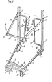
- the carriage illustrated in the drawing comprises two boxes 1, 2 connected together by crosspieces 3 to form a chassis.
- the shoemakers 1, 2 are internally provided with wheels 4 and they support hinges 5 to which the gussets 6 for supporting two side members are articulated.
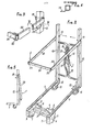
- the side members 7 can be produced by tubes, as shown for example in FIGS. 1 and 7, or by angles as shown in fig. 8, other profiles may also be suitable.
- One of the crosspieces 3 supports stops 8 and the side members 7 are provided on their inner side with wings 9 limiting the measurement by which said side members 7 can pivot relative to the shoemakers 1, 2 to which they are connected by the hinges 5.
- the free end of the side members 7 is fixed, for example welded, on plates 10 below which steerable wheels are mounted 11.
- the plates 10 also serve to support uprights 12, 13.
- the uprights 12, 13 each support a frame 14, respectively 15, the two frames being turned towards one another.
- the frame 15 is provided with a curved upright 16 which carries a pivoting and elastic sliding latch 17.
- centering pieces 18, for example in the shape of an arc of a circle, are fixed on the upright of each of the two frames 14, 15 to achieve mutual interlocking when these two frames are brought into abutment and locked by the latch 17, as shown in FIG. 2.
- the frames 14, 15 can for example be made of tube or round iron or other profiles, the pivoting latch and the centering pieces being made of sheet metal or other material and possibly provided with elastic members, for example rubber.
- the uprights 12, 13 support above the frames 14, 15, pivots 19 on which bars 20, 21 are fixed, one of which is clearly visible in FIG. 3.
- FIG. 3 shows that the joints, such as 22, can be constituted by a simple ring.
- Stops 25 are fixed, for example welded, to each of the uprights 12, 13 to serve as support for the bars 20, 21 and limit their pivoting downwards when they are in the position illustrated in FIGS. 1 to 3, that is to say placed above the side members 7.
- Fig. 5 shows that the bars 20, 21 can be pivoted clockwise to pass to the other side of the uprights 12, 13 thereby freeing up the space above the side members 7.
- the frames 14, 15 extend at a level which is above the side members 7 and below the bars 20, 21.
- the latch 17 is opened for example by sliding it upwards on the upright 16 of the frame 15 then by rotating it, as illustrated by the arrows f 1 , f 2 of FIG . 1.
- the uprights 12, 13 are then spread until the wings 9 come to bear against the stop 8 of the chassis.
- the frames are reassembled and locked, as shown in fig. 2.
- the bars 20, 21 are pivoted to release the side members 7 then plates 26 are placed on the side members.
- the trays 26 are trays intended to contain containers 27, for example milk cartons with a pointed roof 28 and, in this case, the trays form on their undersides notches 29 intended to cover the pointed roof 28 with a row of containers. These are the lateral notches 29 which are used to cover the side members 27, as illustrated in FIGS. 6 and 7.
- the side members 7 are produced by angles, as shown in the fig. 8, or side tabs are attached to the side members 7 if these are formed by tubes.
- Fig. 6 shows that several rows of trays 26 and containers 27 can be stacked on the carriage one above the other.
- the operator Before moving the cart, the operator brings back the bars 20, 21 forming a belt in the position shown in FIG. 6 so that these bars forming a belt with the crosspiece 24 serve to retain at least one of the plates 26; the carriage can then be moved without any risk of falling from any of the plates.
- Fig. 9 illustrates a variant according to which the housings 1, 2 are provided with sleeves 30 for the establishment of a drop side 31.
- a bar 32 terminated by a hook 33 is articulated on one of the frames, for example the frame 14, so that said bar can either lock the side panel 31 by its hook 33, or be brought into a position in which it is designated by 32a and is therefore placed on the other side of the frames 14, 15 to allow the easy installation of the plates 26 or 26a and of the containers 27 which they support.
- the side wall 31 being simply engaged in the sleeves 30 carried by the boxes 1 of the chassis, this side wall is easily removable so that it can easily be removed when there is reason to fit several carriages into each other.
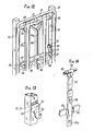
- the side panel 31 has transverse bars 37 allowing it to be fixed to pivoting hooks 35 (fig. 12 and 13) mounted on the uprights 12, 13.
- the hooks 35 allow the side panel to be supported on the carriage when it this is not useful or that the presence of this drop side is not useful.
- the fact that the hooks are pivoting allows them to be retracted inside the uprights 12, 13. The position which the drop side then occupies is clearly shown in FIG. 12.
- the cross 3a which connects the boltiers 1, 2 comprises at least two pairs of sleeves 30, 30a.
- the sleeves 30a replace the stops 8 described in the foregoing and against which the wings 9 come to bear when the uprights 7 are moved apart.
- Each of the two pairs of sleeves 30, 30a can receive the side panel 31, the choice between one or the other pair of sleeves 30 or 30a being dictated by the dimensions presented by the plates 26 which must be supported by the carriage.
- the load of filled trays is maintained by a bar 32 (fig. 10 and 14).
- the bar 32 delimits at one end a hook 33 clearly visible in FIGS. 10 and 17, hook which is intended to be engaged in a recess 41 provided in the upper transverse tube of the side panel 31.
- a second hook 33a attached below the bar 32 which is engaged in the recess 41.
- the retaining bar 32 is articulated by a yoke 43 on a tube 42 extending transversely from one of the uprights 12, 13. As before, the bar 32 can be detached from the side wall 31 and folded back, as illustrated in 32a in fig. 10. It is then advantageously held by an elastic retaining member 44, illustrated in FIG. 14, with a metal ribbon lique rolled on itself.
- the bar 32 is advantageous for the bar 32 to be provided with a gripping member 38, for example a hook to allow it to be mechanically grasped and pivoted and then folded down on the drop side 31 after the loading of the plates on the side members 7.
- a gripping member 38 for example a hook to allow it to be mechanically grasped and pivoted and then folded down on the drop side 31 after the loading of the plates on the side members 7.
- Figs. 10 to 12 show that the uprights 12 and 13 support tubular crosspieces 42 at their upper part and at their lower part, tubular crosspieces which are provided with damping end pieces 51, for example made of rubber or plastic.
- the tubular crosspieces 42 are connected by profiles 14a, 15a in L whose ends are folded back to be fixed to the tubular crosspieces 42.
- the profiles 14a and 15a are arranged, as illustrated in FIG. 15, to be nested one inside the other when the shock absorbing tips 51 are in contact, which is illustrated in FIGS. 10 and 12.
- the invention is not limited to the exemplary embodiments shown and described in detail, because various modifications can be made without departing from its scope.
- the uprights 12, 13 can be produced by cylindrical tubes as illustrated in phantom.
Landscapes
- Engineering & Computer Science (AREA)
- Chemical & Material Sciences (AREA)
- Combustion & Propulsion (AREA)
- Transportation (AREA)
- Mechanical Engineering (AREA)
- Handcart (AREA)
- Pallets (AREA)
- Fittings On The Vehicle Exterior For Carrying Loads, And Devices For Holding Or Mounting Articles (AREA)
- Warehouses Or Storage Devices (AREA)
Priority Applications (1)
| Application Number | Priority Date | Filing Date | Title |
|---|---|---|---|
| AT85400654T ATE58687T1 (de) | 1984-04-27 | 1985-04-02 | Transportwagen fuer behaeltertragende paletten, insbesondere fuer nahrungsmittel. |
Applications Claiming Priority (2)
| Application Number | Priority Date | Filing Date | Title |
|---|---|---|---|
| FR8406710A FR2563488B1 (fr) | 1984-04-27 | 1984-04-27 | Chariot pour le transport de plateaux porte-conteneurs, notamment pour produits alimentaires |
| FR8406710 | 1984-04-27 |
Publications (3)
| Publication Number | Publication Date |
|---|---|
| EP0160598A2 true EP0160598A2 (de) | 1985-11-06 |
| EP0160598A3 EP0160598A3 (en) | 1987-09-16 |
| EP0160598B1 EP0160598B1 (de) | 1990-11-28 |
Family
ID=9303581
Family Applications (1)
| Application Number | Title | Priority Date | Filing Date |
|---|---|---|---|
| EP85400654A Expired - Lifetime EP0160598B1 (de) | 1984-04-27 | 1985-04-02 | Transportwagen für behältertragende Paletten, insbesondere für Nahrungsmittel |
Country Status (4)
| Country | Link |
|---|---|
| EP (1) | EP0160598B1 (de) |
| AT (1) | ATE58687T1 (de) |
| DE (2) | DE160598T1 (de) |
| FR (1) | FR2563488B1 (de) |
Family Cites Families (3)
| Publication number | Priority date | Publication date | Assignee | Title |
|---|---|---|---|---|
| US3873115A (en) * | 1973-02-09 | 1975-03-25 | Hopeman Brothers Inc | Portable stowage rack for beverage containers |
| GB1590951A (en) * | 1977-08-30 | 1981-06-10 | Ross & Bonnyman Eng Ltd | Wheeled pallets |
| SE7910666L (sv) * | 1979-12-27 | 1981-06-28 | Pelly Ab | Anordning vid en lastberare for uppberning och transport av gods |
-
1984
- 1984-04-27 FR FR8406710A patent/FR2563488B1/fr not_active Expired
-
1985
- 1985-04-02 DE DE198585400654T patent/DE160598T1/de active Pending
- 1985-04-02 AT AT85400654T patent/ATE58687T1/de not_active IP Right Cessation
- 1985-04-02 DE DE8585400654T patent/DE3580693D1/de not_active Expired - Fee Related
- 1985-04-02 EP EP85400654A patent/EP0160598B1/de not_active Expired - Lifetime
Also Published As
| Publication number | Publication date |
|---|---|
| EP0160598B1 (de) | 1990-11-28 |
| FR2563488A1 (fr) | 1985-10-31 |
| DE160598T1 (de) | 1986-02-13 |
| FR2563488B1 (fr) | 1986-11-14 |
| ATE58687T1 (de) | 1990-12-15 |
| EP0160598A3 (en) | 1987-09-16 |
| DE3580693D1 (de) | 1991-01-10 |
Similar Documents
| Publication | Publication Date | Title |
|---|---|---|
| EP0202135B1 (de) | Einkaufswagen mit abnehmbaren Behältern zum Gebrauch für Supermarktkunden | |
| EP0337043B1 (de) | Einkaufswagen mit schwenkbarem Korb | |
| EP0778169A1 (de) | Lastkraftwagen-Planenabdeckungs-Vorrichtung | |
| FR2569151A1 (fr) | Chariot de type " caddie " a recipients amovibles | |
| EP2590849B1 (de) | Einkaufswagen | |
| EP3947174B1 (de) | Adaptives lagergestell | |
| EP2230149B1 (de) | Umwandelbarer Transportwagen mit einer Anschlussstruktur mit zwei Vierecken mit variabler Geometrie | |
| EP0160598B1 (de) | Transportwagen für behältertragende Paletten, insbesondere für Nahrungsmittel | |
| WO2016009009A1 (fr) | Rehausse pour palette | |
| WO2013093384A1 (fr) | Chariot d'achats a sacs amovibles | |
| EP0349423B1 (de) | Stapelbarer Einkaufswagen mit einziehbarer Ablage unter dessen Korb | |
| EP0614825B1 (de) | Speditions-Behälter für verschiedene Güter, z.B. für Pakete und/oder für auf Bügeln hängende Kleidungsstücke | |
| FR2577202A1 (fr) | Casier pour le conditionnement d'un lot d'objets, notamment d'objets lourds et volumineux tels que des bouteilles de gaz liquefie | |
| FR2580248A2 (fr) | Chariot de manutention pour recipients amovibles | |
| FR2561601A1 (fr) | Chariot de type " diable " pour le transport d'objets tels que des valises | |
| EP0491595B1 (de) | Stapelbarer Einkaufswagen mit Transportkorb und Vorrichtung zur Ablage von Kasten oder anderem Gut | |
| FR2770192A1 (fr) | Chariot individuel de transport de marchandises | |
| EP0185567A1 (de) | Stützelement für Paletten | |
| FR2806069A1 (fr) | Dispositif de chargement de tourets sur racks de deroulage | |
| FR2747997A1 (fr) | Dispositif de manutention du type a palette | |
| FR2762299A1 (fr) | Casier pour le stockage, le transport et la distribution de bouteilles de gaz | |
| FR2757831A1 (fr) | Palette de manutention d'objets longitudinaux | |
| FR2777550A1 (fr) | Dispositif pliable pour le stockage, la manutention et le transport d'articles divers et installation en faisant application | |
| FR2643032A1 (fr) | Chariot de transport et de manutention pour objets divers, du genre paquets, colis ou analogues | |
| EP0236154A1 (de) | Klappbarer Korbwagen, insbesondere für Selbstbedienungsläder |
Legal Events
| Date | Code | Title | Description |
|---|---|---|---|
| PUAI | Public reference made under article 153(3) epc to a published international application that has entered the european phase |
Free format text: ORIGINAL CODE: 0009012 |
|
| ITCL | It: translation for ep claims filed |
Representative=s name: STUDIO ING. ALFREDO RAIMONDI |
|
| 17P | Request for examination filed |
Effective date: 19850406 |
|
| AK | Designated contracting states |
Designated state(s): AT BE CH DE GB IT LI LU NL SE |
|
| TCAT | At: translation of patent claims filed | ||
| TCNL | Nl: translation of patent claims filed | ||
| DET | De: translation of patent claims | ||
| PUAL | Search report despatched |
Free format text: ORIGINAL CODE: 0009013 |
|
| AK | Designated contracting states |
Kind code of ref document: A3 Designated state(s): AT BE CH DE GB IT LI LU NL SE |
|
| 17Q | First examination report despatched |
Effective date: 19880808 |
|
| GRAA | (expected) grant |
Free format text: ORIGINAL CODE: 0009210 |
|
| AK | Designated contracting states |
Kind code of ref document: B1 Designated state(s): AT BE CH DE GB IT LI LU NL SE |
|
| PG25 | Lapsed in a contracting state [announced via postgrant information from national office to epo] |
Ref country code: IT Free format text: LAPSE BECAUSE OF FAILURE TO SUBMIT A TRANSLATION OF THE DESCRIPTION OR TO PAY THE FEE WITHIN THE PRESCRIBED TIME-LIMIT;WARNING: LAPSES OF ITALIAN PATENTS WITH EFFECTIVE DATE BEFORE 2007 MAY HAVE OCCURRED AT ANY TIME BEFORE 2007. THE CORRECT EFFECTIVE DATE MAY BE DIFFERENT FROM THE ONE RECORDED. Effective date: 19901128 Ref country code: AT Effective date: 19901128 |
|
| REF | Corresponds to: |
Ref document number: 58687 Country of ref document: AT Date of ref document: 19901215 Kind code of ref document: T |
|
| GBT | Gb: translation of ep patent filed (gb section 77(6)(a)/1977) | ||
| REF | Corresponds to: |
Ref document number: 3580693 Country of ref document: DE Date of ref document: 19910110 |
|
| PGFP | Annual fee paid to national office [announced via postgrant information from national office to epo] |
Ref country code: BE Payment date: 19910415 Year of fee payment: 7 |
|
| PGFP | Annual fee paid to national office [announced via postgrant information from national office to epo] |
Ref country code: CH Payment date: 19910423 Year of fee payment: 7 |
|
| PGFP | Annual fee paid to national office [announced via postgrant information from national office to epo] |
Ref country code: DE Payment date: 19910426 Year of fee payment: 7 |
|
| ITTA | It: last paid annual fee | ||
| PGFP | Annual fee paid to national office [announced via postgrant information from national office to epo] |
Ref country code: LU Payment date: 19910502 Year of fee payment: 7 |
|
| K2C2 | Correction of patent specification (partial reprint) published |
Effective date: 19901128 |
|
| PLBE | No opposition filed within time limit |
Free format text: ORIGINAL CODE: 0009261 |
|
| STAA | Information on the status of an ep patent application or granted ep patent |
Free format text: STATUS: NO OPPOSITION FILED WITHIN TIME LIMIT |
|
| EPTA | Lu: last paid annual fee | ||
| 26N | No opposition filed | ||
| PG25 | Lapsed in a contracting state [announced via postgrant information from national office to epo] |
Ref country code: LU Free format text: LAPSE BECAUSE OF NON-PAYMENT OF DUE FEES Effective date: 19920402 |
|
| PG25 | Lapsed in a contracting state [announced via postgrant information from national office to epo] |
Ref country code: CH Effective date: 19920430 Ref country code: BE Effective date: 19920430 Ref country code: LI Effective date: 19920430 |
|
| BERE | Be: lapsed |
Owner name: ELOPAK FRANCE Effective date: 19920430 |
|
| REG | Reference to a national code |
Ref country code: CH Ref legal event code: PL Ref country code: CH Ref legal event code: AUV Free format text: LE BREVET CI-DESSUS EST TOMBE EN DECHEANCE FAUTE DE PAIEMENT, DE LA 8E ANNUITE. |
|
| PG25 | Lapsed in a contracting state [announced via postgrant information from national office to epo] |
Ref country code: DE Effective date: 19930401 |
|
| EAL | Se: european patent in force in sweden |
Ref document number: 85400654.1 |
|
| PGFP | Annual fee paid to national office [announced via postgrant information from national office to epo] |
Ref country code: SE Payment date: 19960318 Year of fee payment: 12 |
|
| PGFP | Annual fee paid to national office [announced via postgrant information from national office to epo] |
Ref country code: NL Payment date: 19960322 Year of fee payment: 12 |
|
| PGFP | Annual fee paid to national office [announced via postgrant information from national office to epo] |
Ref country code: GB Payment date: 19970319 Year of fee payment: 13 |
|
| PG25 | Lapsed in a contracting state [announced via postgrant information from national office to epo] |
Ref country code: SE Effective date: 19970403 |
|
| PG25 | Lapsed in a contracting state [announced via postgrant information from national office to epo] |
Ref country code: NL Effective date: 19971101 |
|
| NLV4 | Nl: lapsed or anulled due to non-payment of the annual fee |
Effective date: 19971101 |
|
| EUG | Se: european patent has lapsed |
Ref document number: 85400654.1 |
|
| PG25 | Lapsed in a contracting state [announced via postgrant information from national office to epo] |
Ref country code: GB Free format text: LAPSE BECAUSE OF NON-PAYMENT OF DUE FEES Effective date: 19980402 |
|
| GBPC | Gb: european patent ceased through non-payment of renewal fee |
Effective date: 19980402 |