EP0160628A2 - Verfahren und Vorrichtung zum Detektieren und Zünden einer von mehreren pyrotechnischen Ladungen - Google Patents
Verfahren und Vorrichtung zum Detektieren und Zünden einer von mehreren pyrotechnischen Ladungen Download PDFInfo
- Publication number
- EP0160628A2 EP0160628A2 EP85850117A EP85850117A EP0160628A2 EP 0160628 A2 EP0160628 A2 EP 0160628A2 EP 85850117 A EP85850117 A EP 85850117A EP 85850117 A EP85850117 A EP 85850117A EP 0160628 A2 EP0160628 A2 EP 0160628A2
- Authority
- EP
- European Patent Office
- Prior art keywords
- firing
- charge
- current
- unit
- circuit
- Prior art date
- Legal status (The legal status is an assumption and is not a legal conclusion. Google has not performed a legal analysis and makes no representation as to the accuracy of the status listed.)
- Granted
Links
Images


Classifications
-
- F—MECHANICAL ENGINEERING; LIGHTING; HEATING; WEAPONS; BLASTING
- F41—WEAPONS
- F41A—FUNCTIONAL FEATURES OR DETAILS COMMON TO BOTH SMALLARMS AND ORDNANCE, e.g. CANNONS; MOUNTINGS FOR SMALLARMS OR ORDNANCE
- F41A19/00—Firing or trigger mechanisms; Cocking mechanisms
- F41A19/58—Electric firing mechanisms
-
- F—MECHANICAL ENGINEERING; LIGHTING; HEATING; WEAPONS; BLASTING
- F42—AMMUNITION; BLASTING
- F42D—BLASTING
- F42D1/00—Blasting methods or apparatus, e.g. loading or tamping
- F42D1/04—Arrangements for ignition
- F42D1/045—Arrangements for electric ignition
- F42D1/05—Electric circuits for blasting
Definitions
- the present invention relates to a device for locating and subsequent firing of a pyrotechnic charge connected in a firing circuit of charges, said device comprising, on the one hand, a current switching unit which is adapted, upon receipt of a voltage pulse indicating that a charge is to be fired, to connect to one of the firing circuits of the firing unit a checking current insufficient for firing a charge, to check whether a charge is connected in the firing circuit concerned, and adapted, if this is not the case, to repeat such connection of checking current for the remaining firing circuits until a connected charge is located and, when this found has happened, to connect a firing current sufficient for firing to the firing circuit in which the charge has been found and, on the other hand, a current detecting unit adapted to effect the said check by detecting if current is flowing through the firing circuit concerned.
- the first- mentioned device which is used mainly for simulating firing from a gun or a tank, comprises fifteen barrels which are loaded with pyrotechnic charges for electric firing, a position selector whose position determines which charge is fired upon receipt of a firing impulse by said device, and a delay circuit preventing double firing upon contact bouncing.
- the position selector When a charge has been fired, the position selector is moved, under the action of a relay, through one step, and when a period of time determined by the delay circuit has expired, the device is ready to fire a new charge.
- this device suffers from the disadvantage that, because there is no possibility of checking if and where charges are provided in the firing unit, the charges must be placed in sequence in the barrels, beginning in the position indicated by the position selector. It is, however, desirable that it should be possible to place the charges in optional positions in the firing unit.
- the British patent specification discloses an apparatus comprising a current switching unit which consists of a manually activated switch which, upon activation, connects a resistor in series with the firing circuit, thereby reducing the current to such an extent that firing cannot take place.
- a bell is used as current detecting unit for detecting whether current is flowing through the connected firing circuit.
- the apparatus thus is essentially mechanical and is operated manually and in that a new firing impulse (a voltage pulse indicating that a charge is to be fired) must be provided for each firing circuit which is to be checked.
- a further object is to allow, upon supply of a firing impulse, firing of the charge first found independently of the position this charge has in the firing unit.
- the device thus automatically locates the positions in which a charge is connected. This is done by connecting a current to one firing circuit at a time. If a charge is connected to this firing circuit, a current will flow through the firing circuit, the charge will be fired, and the current will be detected by a current detecting unit. Scanning of the firing circuits normally starts always on the same firing circuit, but according to a variant of the invention the operator himself may define the starting point of the scanning by not connecting any charge in the firing circuit before the desired starting point. According to this variant, the device first searches out a firing circuit without charge, the current connected to the firing circuits being insufficient for firing a charge.
- the search for a connected charge is begun, and when such a charge is encountered, the firing current is connected to the corresponding firing circuit, and the charge is fired.
- the above-mentioned sequence is carried out automatically by a logic unit connected between the current detecting unit and the current switching unit, said units being activated only when a firing impulse is available on the input of the device.
- FIG. 1 is a block diagram illustrating the principle of the present invention.
- Fig. 2 is a flow diagram illustrating the method according to the present invention.
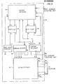
- Fig. 3 is a more detailed block diagram of the logic and selector unit shown in Fig. 1.
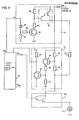
- Fig. 4 is a circuit diagram illustrating a current switching unit, a current detecting unit, and a firing circuit.
- the device comprises a current switching unit 10 which, via a current detecting unit 11, is connected to switches 16 1 - 16 30 . Between each switch 16 1 - 16 30 and earth, a charge may be connected in any one of the firing circuits 17 1 - 17 30 of a firing unit. Furthermore, the device comprises a logic unit 15 having thirty-one outputs 15 0 - 15 30 , of which an output 15 0 is connected to the current switching unit 10 for transmitting a control signal thereto, the remaining thirty outputs 15, - 15 30 being connected each to one switch 16 1 - 16 30 for controlling the state thereof.
- the supply voltage to the logic unit 15 is derived from the firing impulse, i.e. the voltage pulse indicating that a charge is to be fired, and is stabilised by means of a voltage regulator 12.
- the device thus is current-carrying only when the firing impulse has been supplied to the input of the device.
- the logic unit 15 When the device receives a firing impulse (20, Fig. 2), the logic unit 15 is supplied with current via the voltage regulator 12. The logic unit closes the first switch 16 1 (21, Fig. 2) and supplies a low control signal to the current switching unit 10 which supplies a checking current, i.e. a current which is smaller than the firing current (22, Fig. 2) required for the firing of a charge. If a charge is connected in the firing-circuit between the said switch and earth, a current will flow through the detecting unit 11, the switch 16 1 and the firing circuit 17 1 to earth. This current is detected by the detecting unit 11 which supplies a signal to the logic unit 15 signalling that a charge is connected. If, on the other hand, there is no connected charge at this location, the circuit is interrupted, and no current will flow through the current detecting unit 11.
- a checking current i.e. a current which is smaller than the firing current (22, Fig. 2) required for the firing of a charge.
- the device starts by searching for a firing circuit without connected charge (23, Fig. 2), said circuit defining the starting point of the actual search for a connected charge.
- the first switch 16 1 is closed. If a charge is connected at this location, the switch 16 1 is disconnected, and the next switch 16 2 is closed (24, Fig. 2). This procedure is repeated until a firing circuit without connected charge is found. Then the search for a connected charge is begun. This search is effected in the same manner, i.e. the next switch is closed, and the detecting unit 11 detects if any current is flowing in the circuit (25, 26, Fig. 2). If not, scanning is continued on the next firing circuit.
- the logic unit 15 supplies a high control signal to the current switching unit 10 which supplies a firing current to the connected charge which then is fired (27, Fig. 2).
- the firing circuit may be short-circuited.
- a test is made after a predetermined time delay to check if current is still flowing in the firing circuit (28, 29, Fig. 2). if this is the case, the device goes on and tries to fire the next charge (30, Fig. 2). If, however, there is no current flowing in the firing circuit, firing has been completed, and the logic is locked so that nothing more can happen during this firing impulse (31, Fig. 2).
- a gating network 51 has four outputs, two of which are connected to a JK-flip-flop 52, while the other two are connected to another JK-flip-flop 53.
- the Q-output of the JK-flip-flop 52 is connected on the one hand to one input A2 of a status decoder 54 and, on the other hand, back to the gating network 51, while its complementary Q-output only is fed back to the gating network 51.
- the Q-output of the other JK-flip-flop 53 is fed back to the gating network 51, to the second input A of the status decoder 54 and to an enable input on an address counter 55, while its complementary Q-output is connected to a reset input R on a maximum time counter 56, the output of which is fed back to the input M of the gating network 51.
- the address counter 55 has seven outputs corresponding each to one bit in an address. The most significant bit is fed back to the counter, and when this bit is set to one, the counter is stopped. The five least significant bits are connected to a demultiplexor 57, the data input of which is always set to one.
- the demultiplexor 57 has thirty-two outputs of which the first one 57 0 is fed back to the gating network 51, the next thirty outputs 57 1 -57 30 are connected to the corresponding switches 16 1 -16 30 (see Pig. 1) and the last output 57 31 is not being used.
- the status decoder 54 which activates the demultiplexor 57 with a signal on its input E, has an output connected to the current switching unit 10 for transmission of a control signal thereto.
- the logic and selector unit also comprises a resetting circuit (not shown) which, at the beginning of each firing impulse, resets the JK-flip-flops 52, 53, the address counter 55 and the maximum time counter 56. There is also a clock circuit (not shown) supplying clock pulses to the last-mentioned circuits.
- the current through the corresponding firing circuit is sensed, and the result is indicated by means of a signal from the current sensing unit 11 to the gating network 51.
- the Q-output of the JK-flip-flop is set to one, whereupon the device begins to search for a connected charge. Scanning is effected in the same manner as before, and incrementation of the address counter 55 continues.
- the Q-output of the JK-flip-flop 53 is set to one, the address counter 55 being stopped and the status decoder 54 supplying a high control signal to the current switching means 10 which transmits a firing current through the connected firing circuit.
- the maximum time counter 56 begins to count.
- the device will find no empty firing circuit when scanning the thirty firing circuits 17 1 - 17 30 .
- the last output 57 31 of the selector unit is addressed, no current will flow through the current detecting unit 11 because the addressed output is not connected to any firing circuit. This will then be interpreted as a firing circuit without charge, and the device begins to search for a connected charge on the output 57 0 .
- a firing circuit without charge is found directly. The firing circuits are then scanned without encountering any connected charge. When the most significant bit of the addressed counter 55 is one, i.e. when all firing circuits have been scanned twice, scanning is stopped.
- Fig. 4 illustrates the circuit diagram of the current switching unit 10, the current detecting unit 11 and a switch 16 1 for connection of a first firing circuit 17 1 .
- the current switching unit 10 has an input 61 which receives a control signal from the logic and selector unit 15, and an input 62 which receives the firing impulses.
- the input 61 is connected to a zener diode 63 which is connected to earth via a resistor 64 and to the base of a transistor 66 via a resistor 65.
- the input 62 is connected to the collector of the transistor 66 via two resistors 68 and 69 between which the base of a Darlington amplifier 67 is connected.
- a resistor 70 limiting the firing current may be connected between the emitter of the Darlington amplifier 67 and a switch 16 1 .
- the switch 16 1 is a Darlington amplifier which is biased from the corresponding output 15. of the logic unit 15, for connection of a firing circuit 17 1 .
- the other switches 16 2 - 16 30 and the firing circuits 17 2 - 1730 are similarly arranged.
- the current detecting unit 11 comprises two transistor stages.
- the first stage comprises resistors 73, 74 connected in parallel with the Darlington amplifier 67 and the resistor 70, and a transistor 75 whose collector is connected to the second transistor stage.
- the second transistor stage comprises two biasing resistors 76, 77, a collector resistor 78 which is connected to the voltage supply, and a transistor 79.
- the voltage between the collector and emitter of the resistor 79 constitutes the input signal to the logic unit 15.
- the Darlington amplifier which constitutes the switch 16 When the output 15 1 of the logic and selector unit 15 goes high, the Darlington amplifier which constitutes the switch 16, is biased. If a charge is connected in the firing circuit 17 1 between the said switch 16 1 and earth, a closed circuit is formed from the input 62 via the Darlington amplifier 67, the resistor 70 limiting the firing current, the Darlington amplifier 16 1 and the firing circuit 17 1 to earth, as well as through the parallel branch comprising the resistors 73, 74. If the control signal on the input 61 of the current switching unit 10 in this instance is low, the Darlington amplifier 67 is throttled, and but a low current, the checking current, flows through the resistors 73, 74 to the firing circuit 17 1 .
Landscapes
- Engineering & Computer Science (AREA)
- General Engineering & Computer Science (AREA)
- Automotive Seat Belt Assembly (AREA)
- Ignition Installations For Internal Combustion Engines (AREA)
- Electronic Switches (AREA)
- Air Bags (AREA)
Applications Claiming Priority (2)
| Application Number | Priority Date | Filing Date | Title |
|---|---|---|---|
| SE8401889A SE458721B (sv) | 1984-04-05 | 1984-04-05 | Anordning foer uppsoekning och avfyrning av en pyroteknisk laddning |
| SE8401889 | 1984-04-05 |
Publications (3)
| Publication Number | Publication Date |
|---|---|
| EP0160628A2 true EP0160628A2 (de) | 1985-11-06 |
| EP0160628A3 EP0160628A3 (en) | 1986-11-12 |
| EP0160628B1 EP0160628B1 (de) | 1989-12-13 |
Family
ID=20355461
Family Applications (1)
| Application Number | Title | Priority Date | Filing Date |
|---|---|---|---|
| EP85850117A Expired EP0160628B1 (de) | 1984-04-05 | 1985-04-01 | Verfahren und Vorrichtung zum Detektieren und Zünden einer von mehreren pyrotechnischen Ladungen |
Country Status (3)
| Country | Link |
|---|---|
| EP (1) | EP0160628B1 (de) |
| DE (1) | DE3574773D1 (de) |
| SE (1) | SE458721B (de) |
Cited By (3)
| Publication number | Priority date | Publication date | Assignee | Title |
|---|---|---|---|---|
| FR2641860A1 (fr) * | 1988-12-30 | 1990-07-20 | France Etat Armement | Controleur automatique pour circuit pyrotechnique |
| EP0434883A1 (de) * | 1989-12-29 | 1991-07-03 | Union Espanola De Explosivos S.A. | Elektronische Einrichtung mit hoher Zuverlässigkeit für aufeinanderfolgende Detonationen |
| EP0919782A3 (de) * | 1997-11-29 | 2000-10-25 | DaimlerChrysler AG | Entsorgungsgerät und Verfahren zur Entsorgung für Insassenschutzeinrichtungen mit pyrotechnischen Zündern |
Family Cites Families (5)
| Publication number | Priority date | Publication date | Assignee | Title |
|---|---|---|---|---|
| DE2046098C3 (de) * | 1970-09-18 | 1975-11-13 | Licentia Patent-Verwaltungs-Gmbh, 6000 Frankfurt | Schaltungsanordnung zum Zünden der Zündkapseln eines Raketenstartgerätes |
| FR2447004A1 (fr) * | 1979-01-16 | 1980-08-14 | Serat | Perfectionnements apportes aux poignees generateur pour mise a feu des propulseurs de projectile |
| US4324168A (en) * | 1980-09-26 | 1982-04-13 | The Bendix Corporation | Weapon firing system including weapon interrogation means |
| NO167995C (no) * | 1982-07-02 | 1992-01-02 | Schlumberger Ltd | Fremgangsmaate og system for selektiv broenn-perforering ved hjelp av en enkelt ledning. |
| FR2555305A1 (fr) * | 1983-11-21 | 1985-05-24 | Bourdalle Eric | Dispositif de test et tir d'explosifs a allumage electrique |
-
1984
- 1984-04-05 SE SE8401889A patent/SE458721B/sv not_active IP Right Cessation
-
1985
- 1985-04-01 DE DE8585850117T patent/DE3574773D1/de not_active Expired - Lifetime
- 1985-04-01 EP EP85850117A patent/EP0160628B1/de not_active Expired
Cited By (3)
| Publication number | Priority date | Publication date | Assignee | Title |
|---|---|---|---|---|
| FR2641860A1 (fr) * | 1988-12-30 | 1990-07-20 | France Etat Armement | Controleur automatique pour circuit pyrotechnique |
| EP0434883A1 (de) * | 1989-12-29 | 1991-07-03 | Union Espanola De Explosivos S.A. | Elektronische Einrichtung mit hoher Zuverlässigkeit für aufeinanderfolgende Detonationen |
| EP0919782A3 (de) * | 1997-11-29 | 2000-10-25 | DaimlerChrysler AG | Entsorgungsgerät und Verfahren zur Entsorgung für Insassenschutzeinrichtungen mit pyrotechnischen Zündern |
Also Published As
| Publication number | Publication date |
|---|---|
| SE8401889D0 (sv) | 1984-04-05 |
| EP0160628A3 (en) | 1986-11-12 |
| DE3574773D1 (de) | 1990-01-18 |
| EP0160628B1 (de) | 1989-12-13 |
| SE8401889L (sv) | 1985-10-06 |
| SE458721B (sv) | 1989-04-24 |
Similar Documents
| Publication | Publication Date | Title |
|---|---|---|
| US4093946A (en) | Two-wire, multiple-transducer communications system | |
| RU2077699C1 (ru) | Устройство для инициирования электрических нагрузок, способ инициирования электрических нагрузок по истечении предварительно установленных временных задержек и дистанционное электрическое устройство задержки для инициирования электрической нагрузки | |
| EP0793799B1 (de) | Detonatorschaltung | |
| US4583189A (en) | Microprocessor-based scan-mode keying circuit | |
| US3814839A (en) | Remote digital switching technique for use on communications circuits | |
| US4347608A (en) | Self-checking system for electronic processing equipment | |
| JP2721916B2 (ja) | 火災報知設備の断線監視装置 | |
| EP0160628B1 (de) | Verfahren und Vorrichtung zum Detektieren und Zünden einer von mehreren pyrotechnischen Ladungen | |
| US3566399A (en) | Control station monitoring system for remote stations | |
| US5394465A (en) | Parallel phone detection circuit | |
| EP1946190B1 (de) | Verfahren zum zuweisen einer verzögerungszeit an elektronische verzögerungsdetonatoren | |
| US4960033A (en) | Gun firing relay circuit | |
| US4161721A (en) | Alarm device having code verification system | |
| US3371579A (en) | Failsafe fuze-setting system | |
| US4152696A (en) | Multi-function control circuit | |
| US4625205A (en) | Remote control system transmitting a control pulse sequence through interlocked electromechanical relays | |
| US2619282A (en) | Electronic signal responsive predetermining circuit | |
| GB1580868A (en) | Pulse time addition circuit | |
| CA1273999A (en) | Apparatus and method for testing contact interruptions of circuit interconnection devices | |
| US4325130A (en) | Reprogrammable control apparatus | |
| US4520481A (en) | Data-handling system for the exchange of digital messages between two intercommunicating functional units | |
| US3534350A (en) | Electrical protection system | |
| US3403269A (en) | Frequency responsive rc timing circuit for detecting either lack of input or overextended presence of input | |
| EP0611944B1 (de) | Testschaltung | |
| US2561722A (en) | Signaling system |
Legal Events
| Date | Code | Title | Description |
|---|---|---|---|
| PUAI | Public reference made under article 153(3) epc to a published international application that has entered the european phase |
Free format text: ORIGINAL CODE: 0009012 |
|
| AK | Designated contracting states |
Designated state(s): CH DE GB LI |
|
| PUAL | Search report despatched |
Free format text: ORIGINAL CODE: 0009013 |
|
| AK | Designated contracting states |
Kind code of ref document: A3 Designated state(s): CH DE GB LI |
|
| 17P | Request for examination filed |
Effective date: 19861128 |
|
| 17Q | First examination report despatched |
Effective date: 19870710 |
|
| GRAA | (expected) grant |
Free format text: ORIGINAL CODE: 0009210 |
|
| AK | Designated contracting states |
Kind code of ref document: B1 Designated state(s): CH DE GB LI |
|
| REF | Corresponds to: |
Ref document number: 3574773 Country of ref document: DE Date of ref document: 19900118 |
|
| PLBE | No opposition filed within time limit |
Free format text: ORIGINAL CODE: 0009261 |
|
| STAA | Information on the status of an ep patent application or granted ep patent |
Free format text: STATUS: NO OPPOSITION FILED WITHIN TIME LIMIT |
|
| 26N | No opposition filed | ||
| REG | Reference to a national code |
Ref country code: GB Ref legal event code: IF02 |
|
| PGFP | Annual fee paid to national office [announced via postgrant information from national office to epo] |
Ref country code: GB Payment date: 20040331 Year of fee payment: 20 |
|
| PGFP | Annual fee paid to national office [announced via postgrant information from national office to epo] |
Ref country code: DE Payment date: 20040408 Year of fee payment: 20 |
|
| PGFP | Annual fee paid to national office [announced via postgrant information from national office to epo] |
Ref country code: CH Payment date: 20040416 Year of fee payment: 20 |
|
| PG25 | Lapsed in a contracting state [announced via postgrant information from national office to epo] |
Ref country code: GB Free format text: LAPSE BECAUSE OF EXPIRATION OF PROTECTION Effective date: 20050331 |
|
| REG | Reference to a national code |
Ref country code: GB Ref legal event code: PE20 |
|
| REG | Reference to a national code |
Ref country code: CH Ref legal event code: PL |