EP0160662B1 - Wärmetauscher mit mantel und rohrbündel und verfahren dafür - Google Patents
Wärmetauscher mit mantel und rohrbündel und verfahren dafür Download PDFInfo
- Publication number
- EP0160662B1 EP0160662B1 EP84903691A EP84903691A EP0160662B1 EP 0160662 B1 EP0160662 B1 EP 0160662B1 EP 84903691 A EP84903691 A EP 84903691A EP 84903691 A EP84903691 A EP 84903691A EP 0160662 B1 EP0160662 B1 EP 0160662B1
- Authority
- EP
- European Patent Office
- Prior art keywords
- tube
- shell
- layer
- boundary
- space
- Prior art date
- Legal status (The legal status is an assumption and is not a legal conclusion. Google has not performed a legal analysis and makes no representation as to the accuracy of the status listed.)
- Expired
Links
- 238000012546 transfer Methods 0.000 title claims abstract description 40
- 238000000034 method Methods 0.000 title abstract description 6
- 239000012530 fluid Substances 0.000 claims abstract description 47
- 239000010410 layer Substances 0.000 claims abstract description 42
- 239000012792 core layer Substances 0.000 claims abstract description 17
- 239000000463 material Substances 0.000 claims abstract description 10
- 230000000694 effects Effects 0.000 claims abstract description 8
- 238000011161 development Methods 0.000 claims abstract description 5
- 238000004519 manufacturing process Methods 0.000 description 3
- 238000011144 upstream manufacturing Methods 0.000 description 3
- 239000004568 cement Substances 0.000 description 2
- 238000012423 maintenance Methods 0.000 description 2
- 239000000203 mixture Substances 0.000 description 2
- 238000005086 pumping Methods 0.000 description 2
- 238000005266 casting Methods 0.000 description 1
- 230000001413 cellular effect Effects 0.000 description 1
- 239000000919 ceramic Substances 0.000 description 1
- 238000009792 diffusion process Methods 0.000 description 1
- 238000002474 experimental method Methods 0.000 description 1
- 230000006698 induction Effects 0.000 description 1
- 230000001788 irregular Effects 0.000 description 1
- 239000011159 matrix material Substances 0.000 description 1
- 238000011089 mechanical engineering Methods 0.000 description 1
- 238000005498 polishing Methods 0.000 description 1
- 238000007788 roughening Methods 0.000 description 1
- 238000000926 separation method Methods 0.000 description 1
- 239000007787 solid Substances 0.000 description 1
Images

Classifications
-
- F—MECHANICAL ENGINEERING; LIGHTING; HEATING; WEAPONS; BLASTING
- F28—HEAT EXCHANGE IN GENERAL
- F28F—DETAILS OF HEAT-EXCHANGE AND HEAT-TRANSFER APPARATUS, OF GENERAL APPLICATION
- F28F13/00—Arrangements for modifying heat-transfer, e.g. increasing, decreasing
- F28F13/02—Arrangements for modifying heat-transfer, e.g. increasing, decreasing by influencing fluid boundary
-
- F—MECHANICAL ENGINEERING; LIGHTING; HEATING; WEAPONS; BLASTING
- F28—HEAT EXCHANGE IN GENERAL
- F28F—DETAILS OF HEAT-EXCHANGE AND HEAT-TRANSFER APPARATUS, OF GENERAL APPLICATION
- F28F13/00—Arrangements for modifying heat-transfer, e.g. increasing, decreasing
- F28F13/003—Arrangements for modifying heat-transfer, e.g. increasing, decreasing by using permeable mass, perforated or porous materials
Definitions
- This invention is concerned with new shell and tube apparatus for heat transfer and with a new process for heat transfer, as employed in such apparatus.
- EP-A-42613 describes a new process and apparatus for heat transfer by which the heat transfer can be increased without a corresponding disproportionate increase in pumping power, and with avoidance of turbulence in the presence of laminar wake-interference flow.
- EP-A-42613 discloses shell and tube heat exchange apparatus for heat exchange between two fluids comprising:
- An object of the present invention is to provide an improvement on such apparatus, permitting easier manufacture, assembly and disassembly.
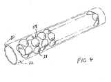
- the spheroidal members (28) and the space-filling material (58) constitute a unitary body, the spheroidal members protruding from the body engaging the inner wall of the tube (20).
- fluid flow within the shell space also takes the form of a non-turbulent boundary layer immediately adjacent to the tube outer surface, and a core-layer interfacing with the boundary-layer, and there is a shell-side fluid flow interrupter structure within the shell space comprising a plurality of spheroidal members surrounding and contacting the tube outer wall, the structure interrupting non-turbulently the full development of at least the boundary-layer at the tube outer surface at a plurality of spaced interruption spots, whereby parts of the interrupted boundary-layer will separate non-turbulently from the tube outer surface between the interruption spots and mix with the core layer to effect heat transfer between the tube outer surface, its respective boundary-layer, and the core-layer; and the space between the shell-side interrupter structure spherical members and the shell inner wall is filled with a space-filling material to prevent useless flow of fluid in a part of the shell interior space remote from the tube outer surface.
- boundary-layers 30 immediately adjacent the passage surfaces 20, which act to insulate the wall surfaces from the main body of the fluid flowing in a core layer 32 between the interfacing with the boundary layers 30, and which therefore reduce the heat transfer between the surfaces 20 and the core layer 32. It is also known that an unobstructed boundary layer increases progressively in thickness in the direction of fluid flow, which will increase its insulating effect.
- the boundary layers 30 are interrupted in a "spot-wise" manner at spaced spots 34 by means of fluid flow interrupter spheres 28 interposed between the heat transfer surfaces, while maintaining a non-turbulent fluid flow in the core 32.
- the heat transfer surfaces 20 not roughened, etc., but on the contrary they are made as smooth as is economically possible, to the extent that in many embodiments the surfaces 20 will be polished to the desired degree of smoothness.
- the disruption of the boundary layers 30 at the multitude of spaced spots 34 ensures that they stay thin, while the manner of their disruption ensures that turbulence is avoided that would cause unduly high friction drag.
- the polishing of all surfaces including those of the spheres also assists in the desired minimizing of the friction drag.
- the ratio of convective heat transfer to friction power per unit heat transfer surface area is improved by providing specially shaped interrupting and mixing structures of low friction drag immediately adjacent a smooth heat transfer surface using hydraulic radii that guarantee total laminar flow.
- the mixing structures contain cellular voids, which are connected with one another. In each of which the fluid rotates spiral-like as a single laminar eddy.
- These eddies are very efficient means of mixing laminar streams, and preferably are obtained by coinciding a wake eddy downstream of an interruption point with an advance eddy upstream of a subsequent interruption point so as to produce wake-interference flow, which provides the highest efficiency.
- boundary layers 30 on the curved surfaces of the mixing structures are fairly thick, whereas the boundary layers of the heat transfer surfaces, situated opposite the mixing-structure surfaces, remain very thin on average because they are reduced regularly and spotwise at the large number of contact points between the surface of the mixing structure and the heat transfer surface, and are in addition exposed to the highest local velocities which occur predominantly very close to the flat heat transfer surface. This allows rapid heat flow through the heat transfer surface.
- the general direction of flow of the fluid is indicated by arrows 31 and the flow interrupter structure causes the production of laminar flow eddies 38 of shape and rotational frequency that depend upon the geometry of the structure.
- Wake-eddies will be produced around the spots of interruption downstream of the flow, while advance eddies will be produced upstream of the flow. If the spacing of the interruption spots 34 is made such that the advance- and wake-eddies of immediately successive spots coincide, then wake-interference flow is obtained whereby, in the absence of turbulent friction-drag, very efficient non-turbulent mixing is obtained between the interrupted boundary-layers 30 and the adjacent core layer 32.
- a turbulent flow which is to be avoided, may be distinguished from an eddy in that the former is irregular and there is no observable pattern as with an eddy. Eddies and swirls therefore do not constitute turbulence. Again a laminar eddy or vortex is confined by solid boundaries or by laminar fluid flows, while a turbulent eddy or vortex will be surrounded by other eddies and vortices which interact with the turbulent eddy or vortex.
- the conditions for maintenance of laminar flow with a particular structure can be observed for example by providing suitable windows in an experimental structure and adding visible fluids to the fluid flow if required.
- the interposed structure it is not necessary for the interposed structure to touch the passage walls as long as it is sufficiently close thereto to provide the necessary extent of interruption to the boundary layers.
- the portion of each spherical surface around the actual point of contact and submerged in the boundary layer will also be effective in this interrupting function.
- the interrupter structure may therefore be suspended within the enclosure and not actually touch the walls, or touch the walls at fewer points than there are interruption points.
- the profile of the interrupter structure elements of the structure of Figure 1 taken in the direction of flow of the fluid in the passage is of course a circle.
- Other profiles can be used and should be such as to present a smoothly contoured surface to the fluid flow, so as to reduce friction losses to a minimum and also to ensure the maintenance of laminar flow, for example an ellipsoidal profile shows an egg-shaped profile and a drop-shaped profile; in the latter two profiles the face of largest radius faces upstream.
- the fluid is very viscous, such as a viscous oil that is to be heated.
- the spacing apart of the parallel walls 20 of the passage can be increased considerably without the establishment of turbulent flow, but such a fluid is usually of low thermal conductivity and a thermal boundary layer will be established immediately adjacent to the heat transfer surface that is much thinner that the respective boundary layer.
- the interposed structure must be arranged to interrupt this thinner thermal boundary-layer irrespective of the thickness of the boundary layer.
- the principal factor in the determination of the thickness of the thermal boundary layer is the Prandtl number, which is high and the thermal conductivity is low.
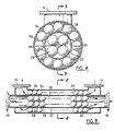
- FIGS 2 and 3 show a single tube-in-shell exchanger as disclosed in EP-A-42613 in which one fluid path with inlet and outlet 14 and is respectively is formed by the annular space between an outer shell 54 and an inner circular cross-section tube 22, while the other fluid path with inlet 48 and outlet 50 is of course formed by the tube 22.
- the annular shell space is of radial dimension just sufficient to receive flow-interrupting spheres 28 and the spaces between the spheres and the inner wall of the outer shell are completely filled with a suitable cementitious material 56 to prevent fluid flow therethrough that would be wasted.
- the interrupter system employed within the tube 22 comprises rows of smaller spheres that used to provide the necessary flow capacity with a suffi- cienty large number of interrupting points 34 both along the length of the tube and also around its circumference. As with the shell-side interrupter system the useless space between the rows if filled with a cementitious or other suitable material 58, such as concrete or ceramic cement.
- the separate spheres 28 and cement 58 in which they are embedded can constitute a unitary structure formed for example by casting, so that the spheroidal members 28 protruding from the central matrix will engage the inner tube wall.
- a unitary structure can be more easily manufactured and more easily assembled into and disassembled from the apparatus.
- successive spheroidal members along the length of the structure are displaced offset circumferentially, giving the same effect as if the rows of spheroidal members had been disposed helically, with a large number of flow interruption points adjacent the tube surface 20 and enhanced reduction of the flow cross-sectional area.
- the cylinder of spheroidal members and the space-filling material 56 that are disposed against the shell inner wall can constitute a cylindrical unitary structure that is slid into position and removed as a unit.
- the invention is applicable to a multiple tube in shell heat exchanger in which a plurality of parallel tubes 22 are disposed within a single outer shell 54.
- the outer spheres 28 may be arranged in rows, circles or helixes thereof with some of the spheres contacting two adjacent tubes, so that it disrupts the boundary layers of both tubes.
Landscapes
- Engineering & Computer Science (AREA)
- Physics & Mathematics (AREA)
- Thermal Sciences (AREA)
- Mechanical Engineering (AREA)
- General Engineering & Computer Science (AREA)
- Dispersion Chemistry (AREA)
- Chemical & Material Sciences (AREA)
- Heat-Exchange Devices With Radiators And Conduit Assemblies (AREA)
- Physical Or Chemical Processes And Apparatus (AREA)
- Details Of Heat-Exchange And Heat-Transfer (AREA)
- Cooling Or The Like Of Electrical Apparatus (AREA)
- Central Heating Systems (AREA)
- Steam Or Hot-Water Central Heating Systems (AREA)
- Feeding, Discharge, Calcimining, Fusing, And Gas-Generation Devices (AREA)
Claims (5)
Priority Applications (1)
| Application Number | Priority Date | Filing Date | Title |
|---|---|---|---|
| AT84903691T ATE34220T1 (de) | 1983-10-05 | 1984-09-19 | Waermetauscher mit mantel und rohrbuendel und verfahren dafuer. |
Applications Claiming Priority (2)
| Application Number | Priority Date | Filing Date | Title |
|---|---|---|---|
| US53919883A | 1983-10-05 | 1983-10-05 | |
| US539198 | 1990-05-11 |
Publications (3)
| Publication Number | Publication Date |
|---|---|
| EP0160662A1 EP0160662A1 (de) | 1985-11-13 |
| EP0160662A4 EP0160662A4 (de) | 1986-02-20 |
| EP0160662B1 true EP0160662B1 (de) | 1988-05-11 |
Family
ID=24150219
Family Applications (1)
| Application Number | Title | Priority Date | Filing Date |
|---|---|---|---|
| EP84903691A Expired EP0160662B1 (de) | 1983-10-05 | 1984-09-19 | Wärmetauscher mit mantel und rohrbündel und verfahren dafür |
Country Status (12)
| Country | Link |
|---|---|
| EP (1) | EP0160662B1 (de) |
| JP (1) | JPS61500132A (de) |
| KR (1) | KR910003073B1 (de) |
| AU (1) | AU585839B2 (de) |
| BR (1) | BR8407108A (de) |
| DE (1) | DE3471157D1 (de) |
| DK (1) | DK247585A (de) |
| IT (1) | IT1176887B (de) |
| MX (1) | MX161055A (de) |
| NO (1) | NO852255L (de) |
| WO (1) | WO1985001571A1 (de) |
| ZA (1) | ZA847652B (de) |
Families Citing this family (1)
| Publication number | Priority date | Publication date | Assignee | Title |
|---|---|---|---|---|
| US20110300050A1 (en) * | 2010-06-08 | 2011-12-08 | Memc Electronic Materials, Inc. | Trichlorosilane Vaporization System |
Family Cites Families (10)
| Publication number | Priority date | Publication date | Assignee | Title |
|---|---|---|---|---|
| US1015261A (en) * | 1910-12-03 | 1912-01-16 | William Arthur Bone | Steam generation-feed-water heating, and heating of liquids generally. |
| FR535531A (fr) * | 1920-07-07 | 1922-04-15 | Bristol Aeroplane Co Ltd | Perfectionnements aux chaudières à tubes d'eau, réchauffeurs d'eau et générateurs de vapeur |
| GB531112A (en) * | 1939-07-12 | 1940-12-30 | Walter Engel | Improvement in or relating to the manufacture of heat exchange units |
| FR1189249A (fr) * | 1957-11-14 | 1959-10-01 | Réacteur nucléaire à liquide bouillant | |
| US3170512A (en) * | 1963-03-29 | 1965-02-23 | Carrier Corp | Heat exchanger |
| US3704748A (en) * | 1970-02-11 | 1972-12-05 | Ratheon Co | Heat transfer structure |
| US3921712A (en) * | 1970-03-02 | 1975-11-25 | American Standard Inc | Heat exchanger structure for a compact boiler and the like |
| US3921711A (en) * | 1972-05-30 | 1975-11-25 | American Standard Inc | Turbulator |
| US4051891A (en) * | 1975-10-01 | 1977-10-04 | Halm Instrument Co., Inc. | Heat transfer block means |
| EP0042613A3 (de) * | 1980-06-24 | 1982-08-11 | Richard Adolf Holl | Vorrichtung und Verfahren zur Wärmeübertragung |
-
1984
- 1984-09-19 KR KR1019850700070A patent/KR910003073B1/ko not_active Expired
- 1984-09-19 EP EP84903691A patent/EP0160662B1/de not_active Expired
- 1984-09-19 JP JP59503630A patent/JPS61500132A/ja active Pending
- 1984-09-19 DE DE8484903691T patent/DE3471157D1/de not_active Expired
- 1984-09-19 WO PCT/US1984/001505 patent/WO1985001571A1/en not_active Ceased
- 1984-09-19 BR BR8407108A patent/BR8407108A/pt not_active IP Right Cessation
- 1984-09-19 AU AU34363/84A patent/AU585839B2/en not_active Ceased
- 1984-09-28 ZA ZA847652A patent/ZA847652B/xx unknown
- 1984-10-03 MX MX202927A patent/MX161055A/es unknown
- 1984-10-05 IT IT23041/84A patent/IT1176887B/it active
-
1985
- 1985-06-03 DK DK247585A patent/DK247585A/da not_active Application Discontinuation
- 1985-06-04 NO NO852255A patent/NO852255L/no unknown
Also Published As
| Publication number | Publication date |
|---|---|
| EP0160662A4 (de) | 1986-02-20 |
| DK247585D0 (da) | 1985-06-03 |
| DE3471157D1 (en) | 1988-06-16 |
| BR8407108A (pt) | 1985-08-27 |
| KR850700066A (ko) | 1985-10-21 |
| EP0160662A1 (de) | 1985-11-13 |
| JPS61500132A (ja) | 1986-01-23 |
| MX161055A (es) | 1990-07-18 |
| IT8423041A0 (it) | 1984-10-05 |
| DK247585A (da) | 1985-06-03 |
| IT1176887B (it) | 1987-08-18 |
| IT8423041A1 (it) | 1986-04-05 |
| AU585839B2 (en) | 1989-06-29 |
| AU3436384A (en) | 1985-04-23 |
| KR910003073B1 (ko) | 1991-05-17 |
| ZA847652B (en) | 1985-05-29 |
| NO852255L (no) | 1985-06-04 |
| WO1985001571A1 (en) | 1985-04-11 |
Similar Documents
| Publication | Publication Date | Title |
|---|---|---|
| US4593754A (en) | Shell and tube heat transfer apparatus and process therefor | |
| US4784218A (en) | Fluid handling apparatus | |
| US2663321A (en) | Tubular heat transfer apparatus | |
| EP0042613A2 (de) | Vorrichtung und Verfahren zur Wärmeübertragung | |
| US4670103A (en) | Fluid handling apparatus | |
| US4881596A (en) | Heat exchange pipe for heat transfer | |
| CN103629952B (zh) | 管道式换热器、其制造方法以及换热设备 | |
| CN110057214B (zh) | 一种换热装置 | |
| US3403727A (en) | Crossflow countercurrent heat exchanger with inner and outer-tube sections made up of closely packed coaxially nested layers of helicoidally wound tubes | |
| EP3992481A1 (de) | Lagergehäuse und dessen anwendung | |
| AU574339B2 (en) | Device interupting boundary layer in heat exchanger tubes | |
| CN115183609A (zh) | 换热器芯体及包括其的印刷电路板式换热器 | |
| US20110240266A1 (en) | Helicoid turbulator for heat exchangers | |
| EP4102169A1 (de) | Rippenstruktur und wärmetauscher | |
| CN101379358A (zh) | 螺旋卷绕的多层管式热交换器及其制造方法 | |
| AU585839B2 (en) | Shell and tube heat transfer apparatus and process therefor | |
| EP3741453B1 (de) | Mischvorrichtung mit umgekehrter gewickelter konfiguration und verwendung | |
| CN113701543A (zh) | 翅片结构及换热器 | |
| JP2012057856A (ja) | 熱交換器用伝熱管、及びこれを用いた熱交換器 | |
| JPS6311493Y2 (de) | ||
| CN113108923B (zh) | 具有微槽群结构的辐射黑体腔及水槽式黑体辐射源 | |
| US1992561A (en) | Method of heat transfer | |
| RU38916U1 (ru) | Пучок оребренных теплообменных труб аппарата воздушного охлаждения газа | |
| RU2030702C1 (ru) | Теплообменная поверхность | |
| CN114152119B (zh) | 波浪形石墨翅片换热器 |
Legal Events
| Date | Code | Title | Description |
|---|---|---|---|
| PUAI | Public reference made under article 153(3) epc to a published international application that has entered the european phase |
Free format text: ORIGINAL CODE: 0009012 |
|
| 17P | Request for examination filed |
Effective date: 19850522 |
|
| AK | Designated contracting states |
Designated state(s): AT BE CH DE FR GB LI NL SE |
|
| R17P | Request for examination filed (corrected) |
Effective date: 19851010 |
|
| EL | Fr: translation of claims filed | ||
| TCNL | Nl: translation of patent claims filed | ||
| TCAT | At: translation of patent claims filed | ||
| A4 | Supplementary search report drawn up and despatched |
Effective date: 19860220 |
|
| DET | De: translation of patent claims | ||
| 17Q | First examination report despatched |
Effective date: 19860917 |
|
| GRAA | (expected) grant |
Free format text: ORIGINAL CODE: 0009210 |
|
| AK | Designated contracting states |
Kind code of ref document: B1 Designated state(s): AT BE CH DE FR GB LI NL SE |
|
| REF | Corresponds to: |
Ref document number: 34220 Country of ref document: AT Date of ref document: 19880515 Kind code of ref document: T |
|
| REF | Corresponds to: |
Ref document number: 3471157 Country of ref document: DE Date of ref document: 19880616 |
|
| ET | Fr: translation filed | ||
| PLBE | No opposition filed within time limit |
Free format text: ORIGINAL CODE: 0009261 |
|
| STAA | Information on the status of an ep patent application or granted ep patent |
Free format text: STATUS: NO OPPOSITION FILED WITHIN TIME LIMIT |
|
| 26N | No opposition filed | ||
| PGFP | Annual fee paid to national office [announced via postgrant information from national office to epo] |
Ref country code: GB Payment date: 19900803 Year of fee payment: 7 |
|
| PGFP | Annual fee paid to national office [announced via postgrant information from national office to epo] |
Ref country code: AT Payment date: 19900913 Year of fee payment: 7 |
|
| PGFP | Annual fee paid to national office [announced via postgrant information from national office to epo] |
Ref country code: FR Payment date: 19900919 Year of fee payment: 7 |
|
| PGFP | Annual fee paid to national office [announced via postgrant information from national office to epo] |
Ref country code: SE Payment date: 19900921 Year of fee payment: 7 |
|
| PGFP | Annual fee paid to national office [announced via postgrant information from national office to epo] |
Ref country code: CH Payment date: 19900925 Year of fee payment: 7 |
|
| PGFP | Annual fee paid to national office [announced via postgrant information from national office to epo] |
Ref country code: NL Payment date: 19900930 Year of fee payment: 7 |
|
| PGFP | Annual fee paid to national office [announced via postgrant information from national office to epo] |
Ref country code: DE Payment date: 19901031 Year of fee payment: 7 |
|
| PGFP | Annual fee paid to national office [announced via postgrant information from national office to epo] |
Ref country code: BE Payment date: 19901108 Year of fee payment: 7 |
|
| PG25 | Lapsed in a contracting state [announced via postgrant information from national office to epo] |
Ref country code: GB Effective date: 19910919 Ref country code: AT Effective date: 19910919 |
|
| PG25 | Lapsed in a contracting state [announced via postgrant information from national office to epo] |
Ref country code: SE Effective date: 19910920 |
|
| PG25 | Lapsed in a contracting state [announced via postgrant information from national office to epo] |
Ref country code: LI Effective date: 19910930 Ref country code: CH Effective date: 19910930 Ref country code: BE Effective date: 19910930 |
|
| BERE | Be: lapsed |
Owner name: VAPOR CORP. Effective date: 19910930 |
|
| PG25 | Lapsed in a contracting state [announced via postgrant information from national office to epo] |
Ref country code: NL Effective date: 19920401 |
|
| GBPC | Gb: european patent ceased through non-payment of renewal fee | ||
| NLV4 | Nl: lapsed or anulled due to non-payment of the annual fee | ||
| PG25 | Lapsed in a contracting state [announced via postgrant information from national office to epo] |
Ref country code: FR Effective date: 19920529 |
|
| REG | Reference to a national code |
Ref country code: CH Ref legal event code: PL |
|
| PG25 | Lapsed in a contracting state [announced via postgrant information from national office to epo] |
Ref country code: DE Effective date: 19920602 |
|
| REG | Reference to a national code |
Ref country code: FR Ref legal event code: ST |
|
| EUG | Se: european patent has lapsed |
Ref document number: 84903691.8 Effective date: 19920408 |