EP0160679B1 - Method and device for measuring the deformation of a rotating shaft - Google Patents
Method and device for measuring the deformation of a rotating shaft Download PDFInfo
- Publication number
- EP0160679B1 EP0160679B1 EP84903998A EP84903998A EP0160679B1 EP 0160679 B1 EP0160679 B1 EP 0160679B1 EP 84903998 A EP84903998 A EP 84903998A EP 84903998 A EP84903998 A EP 84903998A EP 0160679 B1 EP0160679 B1 EP 0160679B1
- Authority
- EP
- European Patent Office
- Prior art keywords
- signal
- calibration
- measuring
- zero
- rotating
- Prior art date
- Legal status (The legal status is an assumption and is not a legal conclusion. Google has not performed a legal analysis and makes no representation as to the accuracy of the status listed.)
- Expired
Links
- 238000000034 method Methods 0.000 title claims description 10
- 230000003068 static effect Effects 0.000 claims 3
- 230000001360 synchronised effect Effects 0.000 description 8
- 239000000446 fuel Substances 0.000 description 3
- 230000006835 compression Effects 0.000 description 2
- 238000007906 compression Methods 0.000 description 2
- 238000010586 diagram Methods 0.000 description 2
- 230000006399 behavior Effects 0.000 description 1
- 230000005540 biological transmission Effects 0.000 description 1
- 230000001419 dependent effect Effects 0.000 description 1
- 230000000694 effects Effects 0.000 description 1
- 239000002184 metal Substances 0.000 description 1
- 238000004804 winding Methods 0.000 description 1
Images

Classifications
-
- G—PHYSICS
- G01—MEASURING; TESTING
- G01B—MEASURING LENGTH, THICKNESS OR SIMILAR LINEAR DIMENSIONS; MEASURING ANGLES; MEASURING AREAS; MEASURING IRREGULARITIES OF SURFACES OR CONTOURS
- G01B7/00—Measuring arrangements characterised by the use of electric or magnetic techniques
- G01B7/16—Measuring arrangements characterised by the use of electric or magnetic techniques for measuring the deformation in a solid, e.g. by resistance strain gauge
-
- G—PHYSICS
- G01—MEASURING; TESTING
- G01L—MEASURING FORCE, STRESS, TORQUE, WORK, MECHANICAL POWER, MECHANICAL EFFICIENCY, OR FLUID PRESSURE
- G01L1/00—Measuring force or stress, in general
- G01L1/20—Measuring force or stress, in general by measuring variations in ohmic resistance of solid materials or of electrically-conductive fluids; by making use of electrokinetic cells, i.e. liquid-containing cells wherein an electrical potential is produced or varied upon the application of stress
- G01L1/22—Measuring force or stress, in general by measuring variations in ohmic resistance of solid materials or of electrically-conductive fluids; by making use of electrokinetic cells, i.e. liquid-containing cells wherein an electrical potential is produced or varied upon the application of stress using resistance strain gauges
-
- G—PHYSICS
- G01—MEASURING; TESTING
- G01L—MEASURING FORCE, STRESS, TORQUE, WORK, MECHANICAL POWER, MECHANICAL EFFICIENCY, OR FLUID PRESSURE
- G01L3/00—Measuring torque, work, mechanical power, or mechanical efficiency, in general
- G01L3/02—Rotary-transmission dynamometers
- G01L3/04—Rotary-transmission dynamometers wherein the torque-transmitting element comprises a torsionally-flexible shaft
- G01L3/10—Rotary-transmission dynamometers wherein the torque-transmitting element comprises a torsionally-flexible shaft involving electric or magnetic means for indicating
- G01L3/108—Rotary-transmission dynamometers wherein the torque-transmitting element comprises a torsionally-flexible shaft involving electric or magnetic means for indicating involving resistance strain gauges
Definitions
- This invention relates to a method of measuring the deformation of rotating shaft according to the preamble of Claim 1.
- calibration means comprise a resistor.
- the torque signal is interrupted to provide a reference signal representative of a known calibration torque.
- the resistor can be chosen with a temperature coefficient.
- the present invention has for its object to further improve known methods. Therefore, the method is characterized according to Claim 1.
- calibration and zero calibration means pick up signals by means of calibration and zero calibration bridges arranged on an annular metal carrier connected with the shaft and having the same temperature as the measuring bridge, the measuring value originating from the measuring bridge is compensated for temperature, whilst a calibration signal of the same order of magnitude as the measuring signal is obtained. Moreover, by the zero calibration signal picked up by means of a zero calibration bridge a satisfactory interpolation of the proportionality error between zero calibration and calibration value is possible. Finally, owing to the accurate zero calibration value it is possible to measure a propulsion value in the direction of length, which differs only little from the zero calibration value and which is a measure for the propulsion of, for example, a vessel.
- the propulsion (propelling pressure) is a very interesting datum for a ship for setting optimum operational conditions of a vessel.
- the number of revolutions and/or the blade of adjustable propellers can be set in dependence on the measured propelling pressure for different navigation conditions.
- GB-A-2077537 describes one strain gauge bridge and calibration signal with "zero" reference level.
- US-A-3 234 787 discloses a load measuring bridge and one compensating bridge.
- the present invention provides a device for measuring the deformation of a rotating shaft.
- a further developed method and the device provided by the invention are described in the dependent claims.
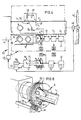
- the rotating shaft 1 is provided with pick-up means 3 formed by a measuring bridge of strain gauges known per se. Furthermore, calibration means are rigidly connected with the shaft 1 so that they rotate together with the shaft 1, said calibration means 7 consisting of a carrying ring 8 having zero calibration means 9 not affected by the deformation of the shaft 1 and proportionality calibration means 10 consisting each of a bridge of strain gauges arranged at such a place in the carrying ring 8 that they have the same temperature as the shaft 1. Finally a first alternating switch 4, amplifying means 20, modulation means 5, transmitting means 6, an oscillator 21 and a secondary feed circuit 24 for the electric feed are rigidly connected with the shaft 1 so that they rotate together with the shaft 1.
- the alternating switches 4 and 13 are synchronously adjustable between a measuring position a, a zero calibration position b, a measuring position c and a proportionality calibration position d by means of any known circuit arrangement.
- This circuit arrangement may comprise a connection 19 of constant voltage S d exceeding any measuring signal whatsoever.
- This voltage source 19 is connected to a contact point d of the alternating switch 4.
- the alternating switch 4 continuously switches in order of succession along the contact points 1, b, c, d, a etc. under the control of a master synchronous oscillator 21.
- the slave synchronous oscillator 22 perceives the high S d signal, it follows by connecting on the contacts d, a, b, c. Then the slave synchronous oscillator 22 has again to perceive the high D d signal in order to again carry out a through-connection d, a, b, c.
- Switch 4 changes each time over from the position 2 to contact point a when it perceives a high signal S d (see Figure 3), since switch 13 is controlled by synchronous oscillator 22, which is synchronized with oscillator 21 by the signal S s .
- the zero signal is applied from the zero calibration means 9 to the amplifying means 20, which apply an amplified signal to modulation means 5.
- the amplified and modulated signal is transmitted by the transmitting means 6, received by the receiving means 11, demodulated by demodulation means 12 and applied, in the zero calibration position b of the alternation switch 13, to the zero calibration signal input 14.
- the zero calibration signal applied to the calculating means 16 is stored in the memory of the calculating means 16.
- the proportionality signal of the proportionality calibration means 10 is applied through the same assembly of amplifying means 20, modulation means 5, demodulation means 12, the transmitting means 6 via the receiving means 11 and the two alternating switches 4 and 13 in processed condition to the proportionality signal input 15 of the calculating means 16, which temporarily store it in a memory concerned.
- a measuring signal is applied through the same assembly of amplifying means 20, modulation means 5 and demodulation means 12 via the transmitting means 6 and receiving means 11 and the two alternating switches 4 and 13 in amplified condition to the measuring signal with the most recent zero processing error and the most recent proportionality processing error.
- the calculation programmed in the calculating means 16 will be explained hereinafter with reference to Figure 2.
- FIG. 4 With the aid of the device 52 of Figure 4 it is possible, for example, to measure the axial compression of a shaft 1 caused by the propulsion of a ship.
- the numerals of Figure 4 equal to those of Figure 1 designate the same functional means.
- a bridge of hook strain gauges 30 formed by two hook strain gauges 26, 27 arranged on both sides of the shaft and two unloaded, corresponding hook strain gauges 28,29 arranged on the carrying ring 8.
- the bridge 30 of hook strain gauges may be connected to contact e of the alternating switch 4.
- the slave synchronous oscillator 22 is synchronized, for exampe, by means of the proportionality calibration signal S c ( Figure 5).
- S c proportionality calibration signal
- control device 40 controls particularly in dependence on the torque signal S a the fuel supply mechanism 44 and controls particularly in dependence on the propulsion signal Sp a propeller blade adjusting mechanism 43 for adjusting the propeller blade angle of the propeller 42 driven by the shaft 1.
- Said control device 40 comprises a computer for calculating and setting the required fuel amount per unit of time and the required propeller angle for the most efficient operation of the ship.
- Figure 6 shows that the aerial of the transmitting means 6 is located substantially in the middle of the annular carrier 8 and opposite the aerial of the fixed pick-up means 11 arranged on an arm 33 in a casing 32.
- the secondary and primary feed windings 24 and 23 respectively for the electric feed of the means arranged on the carrying ring 8.
- bridges of strain gauges 30 are fed by alternating voltage in order to avoid thermo-couple effects.
- a frequency-modulated signal is used for transmitting/receiving.
- a ring 31 thermally well coupled with the shaft 1, on which ring 31 are arranged the unloaded strain gauges 28, 29 as well as the bridges 9, 10.
- An annular cavity 34 is provided in the carrier for accommodating the electric and electronic amplifying, modulation and transmitting means 20, 5 and 6 respectively as well as the alternating switch 4 and the oscillator 21.
Landscapes
- Physics & Mathematics (AREA)
- General Physics & Mathematics (AREA)
- Measurement Of Length, Angles, Or The Like Using Electric Or Magnetic Means (AREA)
- Length Measuring Devices With Unspecified Measuring Means (AREA)
- Heat Treatment Of Articles (AREA)
- A Measuring Device Byusing Mechanical Method (AREA)
- Golf Clubs (AREA)
- Arrangements For Transmission Of Measured Signals (AREA)
Applications Claiming Priority (2)
| Application Number | Priority Date | Filing Date | Title |
|---|---|---|---|
| NL8303745 | 1983-10-31 | ||
| NL8303745A NL8303745A (nl) | 1983-10-31 | 1983-10-31 | Werkwijze en inrichting voor het meten van vervorming van een roterende as. |
Publications (2)
| Publication Number | Publication Date |
|---|---|
| EP0160679A1 EP0160679A1 (en) | 1985-11-13 |
| EP0160679B1 true EP0160679B1 (en) | 1989-10-11 |
Family
ID=19842638
Family Applications (1)
| Application Number | Title | Priority Date | Filing Date |
|---|---|---|---|
| EP84903998A Expired EP0160679B1 (en) | 1983-10-31 | 1984-10-31 | Method and device for measuring the deformation of a rotating shaft |
Country Status (8)
| Country | Link |
|---|---|
| US (1) | US4656875A (da) |
| EP (1) | EP0160679B1 (da) |
| AU (1) | AU584315B2 (da) |
| DE (1) | DE3480115D1 (da) |
| DK (1) | DK163076C (da) |
| FI (1) | FI85541C (da) |
| NL (1) | NL8303745A (da) |
| WO (1) | WO1985002011A1 (da) |
Families Citing this family (13)
| Publication number | Priority date | Publication date | Assignee | Title |
|---|---|---|---|---|
| US5529566A (en) * | 1990-12-11 | 1996-06-25 | Weil; Hans A. | Method for controlling a solid-shell centrifuge |
| US5591925A (en) * | 1991-07-29 | 1997-01-07 | Garshelis; Ivan J. | Circularly magnetized non-contact power sensor and method for measuring torque and power using same |
| US5347871A (en) * | 1992-02-03 | 1994-09-20 | Teledyne Industries, Inc. | Strain sensor |
| DE4318102A1 (de) * | 1993-06-01 | 1994-12-08 | Zahnradfabrik Friedrichshafen | Verfahren zur Vermeidung von Überbeanspruchungen eines Werkstückes beim Schleifen |
| GB2286055B (en) * | 1994-01-29 | 1997-04-16 | British Autogard | Torque indicating device |
| FR2715729B1 (fr) * | 1994-01-29 | 1997-12-12 | British Autogard | Dispositif d'indication de couple. |
| US5672834A (en) * | 1994-01-29 | 1997-09-30 | British Autogard Limited | Torgue indicating device |
| JP2000234966A (ja) * | 1999-02-15 | 2000-08-29 | Showa Corp | トルクセンサの中立点電圧調整装置 |
| US6453742B1 (en) * | 2000-05-31 | 2002-09-24 | Seh America, Inc. | System and method for calibrating semiconductor processing equipment |
| US7681462B2 (en) * | 2006-08-14 | 2010-03-23 | Steorn Limited | System and method for measuring interaction of loads |
| GB2494703B (en) * | 2011-09-16 | 2016-08-03 | Weston Aerospace Ltd | System and method for detecting abnormal movement in a gas turbine shaft |
| CN103673865A (zh) * | 2013-12-09 | 2014-03-26 | 武汉鑫森华科技产业发展有限公司 | 电力变压器绕组变形监测装置 |
| JP6534214B2 (ja) * | 2015-11-11 | 2019-06-26 | 株式会社ロボテック | トルク検出器 |
Family Cites Families (10)
| Publication number | Priority date | Publication date | Assignee | Title |
|---|---|---|---|---|
| US3234787A (en) * | 1961-04-14 | 1966-02-15 | Baldwin Lima Hamilton Corp | Strain gage transducer with impedance means for compensating for the characteristic nonlinearity of the gage |
| US3134279A (en) * | 1961-05-26 | 1964-05-26 | Davy & United Eng Co Ltd | Rolling mills |
| SE325955B (da) * | 1967-10-26 | 1970-07-13 | Saab Ab | |
| US3759093A (en) * | 1971-11-10 | 1973-09-18 | E Farr | Linear load cell bridge including a non-linear strain sensitive element |
| US3797305A (en) * | 1972-01-31 | 1974-03-19 | Indikon Co | Self calibrating strain gage torquemeter |
| US3877300A (en) * | 1972-01-31 | 1975-04-15 | Indikon Company Inc | Measurement of parameters on a rotating member |
| US3850030A (en) * | 1973-10-01 | 1974-11-26 | Acurex Corp | Apparatus for measuring the torsion of a rotating shaft |
| DE2657843A1 (de) * | 1976-12-21 | 1978-06-22 | Bbc Brown Boveri & Cie | Drehmomentmessystem |
| GB2077537B (en) * | 1980-06-05 | 1983-11-09 | Avery Ltd W & T | Digitising circuitry |
| US4535854A (en) * | 1982-11-16 | 1985-08-20 | Pennsylvania Scale Company | Calibration method and apparatus for an electronic weight indicator |
-
1983
- 1983-10-31 NL NL8303745A patent/NL8303745A/nl not_active Application Discontinuation
-
1984
- 1984-10-31 AU AU35597/84A patent/AU584315B2/en not_active Ceased
- 1984-10-31 EP EP84903998A patent/EP0160679B1/en not_active Expired
- 1984-10-31 DE DE8484903998T patent/DE3480115D1/de not_active Expired
- 1984-10-31 US US06/752,188 patent/US4656875A/en not_active Expired - Fee Related
- 1984-10-31 WO PCT/NL1984/000037 patent/WO1985002011A1/en not_active Ceased
-
1985
- 1985-06-18 DK DK274085A patent/DK163076C/da active
- 1985-06-27 FI FI852538A patent/FI85541C/fi not_active IP Right Cessation
Also Published As
| Publication number | Publication date |
|---|---|
| FI852538A0 (fi) | 1985-06-27 |
| FI852538L (fi) | 1985-06-27 |
| DK274085D0 (da) | 1985-06-18 |
| DK274085A (da) | 1985-06-18 |
| DK163076B (da) | 1992-01-13 |
| FI85541C (fi) | 1992-04-27 |
| NL8303745A (nl) | 1985-05-17 |
| WO1985002011A1 (en) | 1985-05-09 |
| EP0160679A1 (en) | 1985-11-13 |
| DK163076C (da) | 1992-06-15 |
| DE3480115D1 (en) | 1989-11-16 |
| US4656875A (en) | 1987-04-14 |
| FI85541B (fi) | 1992-01-15 |
| AU3559784A (en) | 1985-05-22 |
| AU584315B2 (en) | 1989-05-25 |
Similar Documents
| Publication | Publication Date | Title |
|---|---|---|
| AU584315B2 (en) | Measuring deformation of a rotating shaft | |
| JP2880799B2 (ja) | 冷接点補償付き熱電対トランスミッタ | |
| US5191713A (en) | Electronic tilt measuring system | |
| US4763533A (en) | Method and device for measuring the deformation of a rotating shaft | |
| CA2065591A1 (en) | Method and apparatus for measuring electric motor efficiency and loading | |
| EP0805358A3 (en) | Method of and apparatus for calculating position of movable body in navigation system, and method of and apparatus for correcting the position | |
| US3850030A (en) | Apparatus for measuring the torsion of a rotating shaft | |
| JPH0580848A (ja) | エンコーダ | |
| JP2579143B2 (ja) | プロセス変数センサのディジタル補正の方法およびそのためのプロセス変数発信器 | |
| US5521846A (en) | Device for measuring parameters, in particular parameters relating to aircraft or vehicle wheels | |
| EP3736534A1 (en) | Circuit board and unmanned aerial vehicle using circuit board | |
| US20020130020A1 (en) | Rotary switch test sensor | |
| US2486781A (en) | Angle calculating apparatus for use with unstable platforms | |
| EP0188909A2 (en) | Device and method for compensating for sensor error in system calculating dynamic pressure | |
| US4724709A (en) | Pressure measuring system with internal reference | |
| CN108827527A (zh) | 一种基于温度补偿的压力表精度测量系统 | |
| US4950090A (en) | Method for the detection and regulation of a spring moment and a difference speed in rotationally driven two-mass systems | |
| NO168555B (no) | Fremgangsmaate og anordning for aa maale deformasjon i en roterende aksel. | |
| US4435987A (en) | Device for correcting torque detected by an electric dynamometer | |
| GB2230864A (en) | Combination meter system of vehicle | |
| US6822414B2 (en) | Motor controller | |
| US3528293A (en) | Thermistor temperature compensator | |
| US2982958A (en) | Methods and means for measuring various errors in ground reference air navigation systems and equipment | |
| SU1756776A1 (ru) | Способ измерени осевого усили и крут щего момента гребного винта судна и устройство дл его осуществлени | |
| US3225598A (en) | Automatic pressure altimeter |
Legal Events
| Date | Code | Title | Description |
|---|---|---|---|
| PUAI | Public reference made under article 153(3) epc to a published international application that has entered the european phase |
Free format text: ORIGINAL CODE: 0009012 |
|
| 17P | Request for examination filed |
Effective date: 19850724 |
|
| AK | Designated contracting states |
Designated state(s): BE CH DE FR GB LI NL SE |
|
| 17Q | First examination report despatched |
Effective date: 19870513 |
|
| GRAA | (expected) grant |
Free format text: ORIGINAL CODE: 0009210 |
|
| AK | Designated contracting states |
Kind code of ref document: B1 Designated state(s): BE CH DE FR GB LI NL SE |
|
| REF | Corresponds to: |
Ref document number: 3480115 Country of ref document: DE Date of ref document: 19891116 |
|
| RAP2 | Party data changed (patent owner data changed or rights of a patent transferred) |
Owner name: TECHNO FYSICA B.V. |
|
| ET | Fr: translation filed | ||
| BECN | Be: change of holder's name |
Effective date: 19891011 |
|
| NLT2 | Nl: modifications (of names), taken from the european patent patent bulletin |
Owner name: TECHNO FYSICA B.V. TE BARENDRECHT. |
|
| PLBE | No opposition filed within time limit |
Free format text: ORIGINAL CODE: 0009261 |
|
| STAA | Information on the status of an ep patent application or granted ep patent |
Free format text: STATUS: NO OPPOSITION FILED WITHIN TIME LIMIT |
|
| 26N | No opposition filed | ||
| REG | Reference to a national code |
Ref country code: FR Ref legal event code: ST |
|
| REG | Reference to a national code |
Ref country code: FR Ref legal event code: RC |
|
| PGFP | Annual fee paid to national office [announced via postgrant information from national office to epo] |
Ref country code: FR Payment date: 19911031 Year of fee payment: 8 |
|
| PGFP | Annual fee paid to national office [announced via postgrant information from national office to epo] |
Ref country code: SE Payment date: 19911104 Year of fee payment: 8 |
|
| PGFP | Annual fee paid to national office [announced via postgrant information from national office to epo] |
Ref country code: CH Payment date: 19911113 Year of fee payment: 8 |
|
| REG | Reference to a national code |
Ref country code: FR Ref legal event code: DR |
|
| PGFP | Annual fee paid to national office [announced via postgrant information from national office to epo] |
Ref country code: GB Payment date: 19920925 Year of fee payment: 9 |
|
| PGFP | Annual fee paid to national office [announced via postgrant information from national office to epo] |
Ref country code: DE Payment date: 19921030 Year of fee payment: 9 |
|
| PG25 | Lapsed in a contracting state [announced via postgrant information from national office to epo] |
Ref country code: LI Effective date: 19921031 Ref country code: CH Effective date: 19921031 |
|
| PGFP | Annual fee paid to national office [announced via postgrant information from national office to epo] |
Ref country code: NL Payment date: 19921031 Year of fee payment: 9 |
|
| PG25 | Lapsed in a contracting state [announced via postgrant information from national office to epo] |
Ref country code: SE Effective date: 19921101 |
|
| PGFP | Annual fee paid to national office [announced via postgrant information from national office to epo] |
Ref country code: BE Payment date: 19921104 Year of fee payment: 9 |
|
| PG25 | Lapsed in a contracting state [announced via postgrant information from national office to epo] |
Ref country code: FR Effective date: 19930630 |
|
| REG | Reference to a national code |
Ref country code: CH Ref legal event code: PL |
|
| REG | Reference to a national code |
Ref country code: FR Ref legal event code: ST |
|
| PG25 | Lapsed in a contracting state [announced via postgrant information from national office to epo] |
Ref country code: GB Effective date: 19931031 Ref country code: BE Effective date: 19931031 |
|
| BERE | Be: lapsed |
Owner name: TECHNO FYSICA B.V. Effective date: 19931031 |
|
| PG25 | Lapsed in a contracting state [announced via postgrant information from national office to epo] |
Ref country code: NL Effective date: 19940501 |
|
| NLV4 | Nl: lapsed or anulled due to non-payment of the annual fee | ||
| GBPC | Gb: european patent ceased through non-payment of renewal fee |
Effective date: 19931031 |
|
| PG25 | Lapsed in a contracting state [announced via postgrant information from national office to epo] |
Ref country code: DE Effective date: 19940701 |
|
| EUG | Se: european patent has lapsed |
Ref document number: 84903998.7 Effective date: 19930610 |