EP0160714A1 - Arrangement pour le suivi de piste de têtes rotatives - Google Patents
Arrangement pour le suivi de piste de têtes rotatives Download PDFInfo
- Publication number
- EP0160714A1 EP0160714A1 EP84105001A EP84105001A EP0160714A1 EP 0160714 A1 EP0160714 A1 EP 0160714A1 EP 84105001 A EP84105001 A EP 84105001A EP 84105001 A EP84105001 A EP 84105001A EP 0160714 A1 EP0160714 A1 EP 0160714A1
- Authority
- EP
- European Patent Office
- Prior art keywords
- rotating
- piezo elements
- magnetic heads
- magnetic
- rotating holder
- Prior art date
- Legal status (The legal status is an assumption and is not a legal conclusion. Google has not performed a legal analysis and makes no representation as to the accuracy of the status listed.)
- Granted
Links
Images
Classifications
-
- G—PHYSICS
- G11—INFORMATION STORAGE
- G11B—INFORMATION STORAGE BASED ON RELATIVE MOVEMENT BETWEEN RECORD CARRIER AND TRANSDUCER
- G11B15/00—Driving, starting or stopping record carriers of filamentary or web form; Driving both such record carriers and heads; Guiding such record carriers or containers therefor; Control thereof; Control of operating function
- G11B15/18—Driving; Starting; Stopping; Arrangements for control or regulation thereof
- G11B15/1808—Driving of both record carrier and head
- G11B15/1825—Driving of both record carrier and head driving or moving the head in a direction which cuts across the direction of travel of the tape, e.g. for helicoïdal scanning
- G11B15/1833—Driving of both record carrier and head driving or moving the head in a direction which cuts across the direction of travel of the tape, e.g. for helicoïdal scanning with head driven in a plane, cyclically around an axis, e.g. on headwheel
- G11B15/1841—Driving of both record carrier and head driving or moving the head in a direction which cuts across the direction of travel of the tape, e.g. for helicoïdal scanning with head driven in a plane, cyclically around an axis, e.g. on headwheel with provision for information tracking by moving the transducing part of the head relative to the headwheel, in the direction of the scanning movement, e.g. for skew or time base correction
-
- G—PHYSICS
- G11—INFORMATION STORAGE
- G11B—INFORMATION STORAGE BASED ON RELATIVE MOVEMENT BETWEEN RECORD CARRIER AND TRANSDUCER
- G11B5/00—Recording by magnetisation or demagnetisation of a record carrier; Reproducing by magnetic means; Record carriers therefor
- G11B5/48—Disposition or mounting of heads or head supports relative to record carriers ; arrangements of heads, e.g. for scanning the record carrier to increase the relative speed
- G11B5/52—Disposition or mounting of heads or head supports relative to record carriers ; arrangements of heads, e.g. for scanning the record carrier to increase the relative speed with simultaneous movement of head and record carrier, e.g. rotation of head
- G11B5/53—Disposition or mounting of heads on rotating support
-
- G—PHYSICS
- G11—INFORMATION STORAGE
- G11B—INFORMATION STORAGE BASED ON RELATIVE MOVEMENT BETWEEN RECORD CARRIER AND TRANSDUCER
- G11B5/00—Recording by magnetisation or demagnetisation of a record carrier; Reproducing by magnetic means; Record carriers therefor
- G11B5/48—Disposition or mounting of heads or head supports relative to record carriers ; arrangements of heads, e.g. for scanning the record carrier to increase the relative speed
- G11B5/58—Disposition or mounting of heads or head supports relative to record carriers ; arrangements of heads, e.g. for scanning the record carrier to increase the relative speed with provision for moving the head for the purpose of maintaining alignment of the head relative to the record carrier during transducing operation, e.g. to compensate for surface irregularities of the latter or for track following
- G11B5/584—Disposition or mounting of heads or head supports relative to record carriers ; arrangements of heads, e.g. for scanning the record carrier to increase the relative speed with provision for moving the head for the purpose of maintaining alignment of the head relative to the record carrier during transducing operation, e.g. to compensate for surface irregularities of the latter or for track following for track following on tapes
- G11B5/588—Disposition or mounting of heads or head supports relative to record carriers ; arrangements of heads, e.g. for scanning the record carrier to increase the relative speed with provision for moving the head for the purpose of maintaining alignment of the head relative to the record carrier during transducing operation, e.g. to compensate for surface irregularities of the latter or for track following for track following on tapes by controlling the position of the rotating heads
- G11B5/592—Disposition or mounting of heads or head supports relative to record carriers ; arrangements of heads, e.g. for scanning the record carrier to increase the relative speed with provision for moving the head for the purpose of maintaining alignment of the head relative to the record carrier during transducing operation, e.g. to compensate for surface irregularities of the latter or for track following for track following on tapes by controlling the position of the rotating heads using bimorph elements supporting the heads
Definitions
- the invention relates to a device for the tracking of rotating magnetic heads in magnetic tape devices, in which piezo elements are used as carriers of the magnetic heads, which are firmly clamped at one end in a rotating holder and are connected at their deflectable end to the magnetic head.
- Piezo elements in this context also called “actuators” or bimorphs ” have been used for example in video recorders for tracking purposes.
- the free ends of the magnetic heads are attached to them.
- the piezo elements have the property that when a voltage is applied, they depend on the polarity be deflected in one direction or the other so that the magnet heads can be moved perpendicular to the scanning direction. If you control the piezo elements with a control voltage according to the tracking error, the video heads follow the intended tracks exactly.
- the piezo elements are firmly clamped in a piezo element holder, which either rotates itself or is rigidly connected to the rotating head wheel of the video recorder.
- the free-swinging length of the piezo element is a measure of the head deflection that can be achieved.
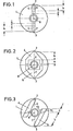
- Figures 1 and 2 show known arrangements for tracking in video recorders.
- the magnetic heads 2 and 3 are attached (e.g. glued) to the free-swinging ends of the piezo elements 4 and 5.
- the free-swinging lengths of the piezo elements are designated by b.
- the piezo elements are clamped in a piezo element holder 1, which is either itself designed as a rotating part or is rigidly connected to the rotating head wheel of the video recorder.
- the clamping length of the piezo elements in the piezo element holder is designated by a.
- the present invention is therefore based on the object of providing a device for increasing the piezo element deflection which is particularly suitable for small magnetic tape devices, is inexpensive and enables the magnetically recorded signals to be reproduced practically without azimuth errors.
- the piezo elements extend obliquely to the connecting line between the associated magnetic head and the fulcrum of the rotating holder up to approximately the height of this fulcrum and in that the piezo elements are clamped obliquely in the rotating holder to avoid azimuth errors.
- the advantages of the invention lie in the fact that the free-floating lengths of the piezo elements and thus the achievable deflection are increased, in particular in magnetic tape devices with small head wheels.
- the magnetic heads 2 and 3 are attached to the free-swinging ends of the piezo elements 4 and 5.
- the free-swinging lengths of the piezo elements are designated by b.
- the piezo elements 4, 5 obliquely to the connecting line 6, 7 between the associated magnetic head 2, 3 and pivot point 8 of the rotating holder 1 By arranging the piezo elements 4, 5 obliquely to the connecting line 6, 7 between the associated magnetic head 2, 3 and pivot point 8 of the rotating holder 1 to approximately the level of this pivot point, the free-swinging length of each piezo element is increased. At their other ends, the piezo elements are clamped in the piezo element holder 1. In contrast to the prior art, this clamping is carried out obliquely in order to compensate for the azimuth errors of the magnetic heads that would otherwise be expected when the piezo elements were deflected. This enables a practically azimuth error-free reproduction of the magnetically recorded signals.
- the clamping length by which the mean value of the distances a 1 and a 2 is understood here, is denoted by a.
- the achievable deflection of the piezo elements is increased compared to the prior art under otherwise identical conditions (in particular with the same control voltage).
- the invention is not restricted to the present exemplary embodiment. For example, it does not matter what type the connections between the magnetic head and the piezo element and the piezo element and the piezo element holder are.
Landscapes
- Adjustment Of The Magnetic Head Position Track Following On Tapes (AREA)
Priority Applications (3)
| Application Number | Priority Date | Filing Date | Title |
|---|---|---|---|
| DE8484105001T DE3475578D1 (en) | 1984-05-03 | 1984-05-03 | Device for the track following of rotating magnetic heads |
| EP84105001A EP0160714B1 (fr) | 1984-05-03 | 1984-05-03 | Arrangement pour le suivi de piste de têtes rotatives |
| AT84105001T ATE39195T1 (de) | 1984-05-03 | 1984-05-03 | Einrichtung fuer die spurnachfuehrung von rotierenden magnetkoepfen. |
Applications Claiming Priority (1)
| Application Number | Priority Date | Filing Date | Title |
|---|---|---|---|
| EP84105001A EP0160714B1 (fr) | 1984-05-03 | 1984-05-03 | Arrangement pour le suivi de piste de têtes rotatives |
Publications (2)
| Publication Number | Publication Date |
|---|---|
| EP0160714A1 true EP0160714A1 (fr) | 1985-11-13 |
| EP0160714B1 EP0160714B1 (fr) | 1988-12-07 |
Family
ID=8191920
Family Applications (1)
| Application Number | Title | Priority Date | Filing Date |
|---|---|---|---|
| EP84105001A Expired EP0160714B1 (fr) | 1984-05-03 | 1984-05-03 | Arrangement pour le suivi de piste de têtes rotatives |
Country Status (3)
| Country | Link |
|---|---|
| EP (1) | EP0160714B1 (fr) |
| AT (1) | ATE39195T1 (fr) |
| DE (1) | DE3475578D1 (fr) |
Citations (6)
| Publication number | Priority date | Publication date | Assignee | Title |
|---|---|---|---|---|
| DE2741217A1 (de) * | 1976-09-13 | 1978-03-16 | Ampex | Bewegliche halterung mit antriebsvorrichtung fuer einen relativ zu einem aufzeichnungstraeger bewegbaren wandler |
| FR2414840A1 (fr) * | 1978-01-17 | 1979-08-10 | Sony Corp | Ensemble de support de tetes magnetiques pour magnetoscope |
| US4295172A (en) * | 1978-11-10 | 1981-10-13 | Matsushita Electric Industrial Co., Ltd. | Rotary magnetic head apparatus |
| US4326228A (en) * | 1979-03-09 | 1982-04-20 | Sony Corporation | Magnetic transducer supporting apparatus |
| GB2113450A (en) * | 1978-11-01 | 1983-08-03 | Ampex | Magnetic transducing head mount |
| JPS5919225A (ja) * | 1982-07-20 | 1984-01-31 | Matsushita Electric Ind Co Ltd | 回転磁気ヘツド装置 |
-
1984
- 1984-05-03 EP EP84105001A patent/EP0160714B1/fr not_active Expired
- 1984-05-03 AT AT84105001T patent/ATE39195T1/de active
- 1984-05-03 DE DE8484105001T patent/DE3475578D1/de not_active Expired
Patent Citations (6)
| Publication number | Priority date | Publication date | Assignee | Title |
|---|---|---|---|---|
| DE2741217A1 (de) * | 1976-09-13 | 1978-03-16 | Ampex | Bewegliche halterung mit antriebsvorrichtung fuer einen relativ zu einem aufzeichnungstraeger bewegbaren wandler |
| FR2414840A1 (fr) * | 1978-01-17 | 1979-08-10 | Sony Corp | Ensemble de support de tetes magnetiques pour magnetoscope |
| GB2113450A (en) * | 1978-11-01 | 1983-08-03 | Ampex | Magnetic transducing head mount |
| US4295172A (en) * | 1978-11-10 | 1981-10-13 | Matsushita Electric Industrial Co., Ltd. | Rotary magnetic head apparatus |
| US4326228A (en) * | 1979-03-09 | 1982-04-20 | Sony Corporation | Magnetic transducer supporting apparatus |
| JPS5919225A (ja) * | 1982-07-20 | 1984-01-31 | Matsushita Electric Ind Co Ltd | 回転磁気ヘツド装置 |
Non-Patent Citations (5)
| Title |
|---|
| PATENTS ABSTRACTS OF JAPAN, Band 4, Nr. 110 (P-22)[592], 8. August 1980, Seite 29 P 22; & JP - A - 55 67 938 (MATSUSHITA DENKI SANGYO K.K.) 22.05.1980 * |
| PATENTS ABSTRACTS OF JAPAN, Band 4, Nr. 70 (P-12)[552], 23. Mai 1980, Seite 150 P 12; & JP - A - 55 38 626 (MATSUSHITA DENKI SANGYO K.K.) 18.03.1980 * |
| PATENTS ABSTRACTS OF JAPAN, Band 6, Nr. 82 (P-116)[960], 20. Mai 1982; & JP - A - 57 18 019 (MATSUSHITA DENKI SANGYO K.K.) 29.01.1982 * |
| PATENTS ABSTRACTS OF JAPAN, Band 7, Nr. 152 (P-208)[1297], 5. Juli 1983; & JP - A - 58 62 822 (MATSUSHITA DENKI SANGYO K.K.) 14.04.1983 * |
| PATENTS ABSTRACTS OF JAPAN, Band 8, Nr. 18 (P-250)[1455], 26. Januar 1984; & JP - A - 58 175 131 (SANYO DENKI K.K.) 14.10.1983 * |
Also Published As
| Publication number | Publication date |
|---|---|
| EP0160714B1 (fr) | 1988-12-07 |
| DE3475578D1 (en) | 1989-01-12 |
| ATE39195T1 (de) | 1988-12-15 |
Similar Documents
| Publication | Publication Date | Title |
|---|---|---|
| DE2760206C2 (fr) | ||
| DE2944108C2 (de) | Vorrichtung zur Halterung und Positionseinstellung einer Magnetwandleranordnung | |
| DE2711976A1 (de) | Magnetkopfeinheit fuer videobandaufzeichnungsgeraete | |
| DE8237135U1 (de) | Vorrichtung zum vorschieben und zurueckziehen eines magnetkopfes | |
| DE3040527C2 (fr) | ||
| DE2651733C3 (de) | Vorrichtung zum Positionieren eines Magnetkopfs | |
| DE69507638T2 (de) | Speichereinheit mit direktem zugriff mit magnetoresistivem wandlerkopf | |
| DE3134480C2 (fr) | ||
| DE3723428A1 (de) | Magnetkopfeinstellvorrichtung | |
| DE3045541A1 (de) | Verfahren und anordnung zur wiedergabe von auf einenaufzeichnungstraeger in einzelnen spuren aufgezeichneten videosignalen | |
| DE3008464C2 (de) | Anordnung zum Auslenken eines Magnetkopfes in Querrichtung zu einer Aufnahmesp ur eines Aufzeichnungsträgers | |
| EP0160714B1 (fr) | Arrangement pour le suivi de piste de têtes rotatives | |
| DE69920868T2 (de) | Spurfolge-servosignalmusterschreibmethode für magnetplattenvorrichtung | |
| DE2852167A1 (de) | Abtasteinrichtung fuer ein magnetbandgeraet zur aufzeichnung und/oder wiedergabe breitbandiger signale | |
| DE2417000A1 (de) | Elektrisch gesteuertes lichtablenksystem | |
| DE4112105C2 (de) | Plattenanordnung | |
| DE3421219A1 (de) | Kopfradanordnung | |
| EP0185844B1 (fr) | Support de tête avec tête magnétique | |
| DE3608279A1 (de) | Magnetkopf | |
| DE2740770A1 (de) | Vorrichtung zum aufnehmen und/oder wiedergeben eines videosignales | |
| EP0518123B1 (fr) | Dispositif pour tête magnétique pour l'enregistrement hélicoidal avec azimut asymétrique | |
| DE4223893C2 (de) | Rotierende Abtasteinrichtung | |
| DE69123419T2 (de) | Aufzeichnungsgerät und Wiedergabegerät mit drehbaren Magnetköpfen | |
| DE1966211C3 (de) | Vorrichtung zum Einstellen der Magnetköpfe eines Magnetplattenspeichers | |
| EP0216293A2 (fr) | Procédé pour l'enregistrement d'un signal sur une bande magnétique |
Legal Events
| Date | Code | Title | Description |
|---|---|---|---|
| PUAI | Public reference made under article 153(3) epc to a published international application that has entered the european phase |
Free format text: ORIGINAL CODE: 0009012 |
|
| AK | Designated contracting states |
Designated state(s): AT BE CH DE FR GB IT LI |
|
| 17P | Request for examination filed |
Effective date: 19860424 |
|
| 17Q | First examination report despatched |
Effective date: 19870910 |
|
| GRAA | (expected) grant |
Free format text: ORIGINAL CODE: 0009210 |
|
| AK | Designated contracting states |
Kind code of ref document: B1 Designated state(s): AT BE CH DE FR GB IT LI |
|
| REF | Corresponds to: |
Ref document number: 39195 Country of ref document: AT Date of ref document: 19881215 Kind code of ref document: T |
|
| GBT | Gb: translation of ep patent filed (gb section 77(6)(a)/1977) | ||
| REF | Corresponds to: |
Ref document number: 3475578 Country of ref document: DE Date of ref document: 19890112 |
|
| ET | Fr: translation filed | ||
| ITF | It: translation for a ep patent filed | ||
| PLBE | No opposition filed within time limit |
Free format text: ORIGINAL CODE: 0009261 |
|
| STAA | Information on the status of an ep patent application or granted ep patent |
Free format text: STATUS: NO OPPOSITION FILED WITHIN TIME LIMIT |
|
| 26N | No opposition filed | ||
| ITTA | It: last paid annual fee | ||
| PGFP | Annual fee paid to national office [announced via postgrant information from national office to epo] |
Ref country code: BE Payment date: 19930422 Year of fee payment: 10 |
|
| REG | Reference to a national code |
Ref country code: GB Ref legal event code: 746 Effective date: 19930526 |
|
| REG | Reference to a national code |
Ref country code: FR Ref legal event code: DL |
|
| ITPR | It: changes in ownership of a european patent |
Owner name: OFFERTA DI LICENZA AL PUBBLICO |
|
| PG25 | Lapsed in a contracting state [announced via postgrant information from national office to epo] |
Ref country code: BE Effective date: 19940531 |
|
| BERE | Be: lapsed |
Owner name: GRUNDIG E.M.V. ELEKTRO-MECHANISCHE VERSUCHSANSTAL Effective date: 19940531 |
|
| REG | Reference to a national code |
Ref country code: CH Ref legal event code: PFA Free format text: GRUNDIG E.M.V. ELEKTRO- MECHANISCHE VERSUCHSANSTALT MAX GRUNDIG GMBH & CO. KG |
|
| REG | Reference to a national code |
Ref country code: CH Ref legal event code: PFA Free format text: GRUNDIG E.M.V. ELEKTRO- MECHANISCHE VERSUCHSANSTALT MAX GRUNDIG GMBH & CO. KG TRANSFER- GRUNDIG AG |
|
| REG | Reference to a national code |
Ref country code: FR Ref legal event code: TP |
|
| PGFP | Annual fee paid to national office [announced via postgrant information from national office to epo] |
Ref country code: AT Payment date: 20000531 Year of fee payment: 17 |
|
| PG25 | Lapsed in a contracting state [announced via postgrant information from national office to epo] |
Ref country code: AT Free format text: LAPSE BECAUSE OF NON-PAYMENT OF DUE FEES Effective date: 20010503 |
|
| REG | Reference to a national code |
Ref country code: GB Ref legal event code: IF02 |
|
| PGFP | Annual fee paid to national office [announced via postgrant information from national office to epo] |
Ref country code: GB Payment date: 20030422 Year of fee payment: 20 |
|
| PGFP | Annual fee paid to national office [announced via postgrant information from national office to epo] |
Ref country code: FR Payment date: 20030522 Year of fee payment: 20 |
|
| PGFP | Annual fee paid to national office [announced via postgrant information from national office to epo] |
Ref country code: CH Payment date: 20030530 Year of fee payment: 20 |
|
| PGFP | Annual fee paid to national office [announced via postgrant information from national office to epo] |
Ref country code: DE Payment date: 20030801 Year of fee payment: 20 |
|
| PG25 | Lapsed in a contracting state [announced via postgrant information from national office to epo] |
Ref country code: LI Free format text: LAPSE BECAUSE OF EXPIRATION OF PROTECTION Effective date: 20040502 Ref country code: GB Free format text: LAPSE BECAUSE OF EXPIRATION OF PROTECTION Effective date: 20040502 Ref country code: CH Free format text: LAPSE BECAUSE OF EXPIRATION OF PROTECTION Effective date: 20040502 |
|
| REG | Reference to a national code |
Ref country code: GB Ref legal event code: PE20 |
|
| REG | Reference to a national code |
Ref country code: CH Ref legal event code: PL |