EP0160800A2 - Device for controlling contents of tabacco on cigarette machine - Google Patents
Device for controlling contents of tabacco on cigarette machine Download PDFInfo
- Publication number
- EP0160800A2 EP0160800A2 EP85102176A EP85102176A EP0160800A2 EP 0160800 A2 EP0160800 A2 EP 0160800A2 EP 85102176 A EP85102176 A EP 85102176A EP 85102176 A EP85102176 A EP 85102176A EP 0160800 A2 EP0160800 A2 EP 0160800A2
- Authority
- EP
- European Patent Office
- Prior art keywords
- tobacco
- output signal
- density detector
- control device
- signal
- Prior art date
- Legal status (The legal status is an assumption and is not a legal conclusion. Google has not performed a legal analysis and makes no representation as to the accuracy of the status listed.)
- Withdrawn
Links
Images




Classifications
-
- A—HUMAN NECESSITIES
- A24—TOBACCO; CIGARS; CIGARETTES; SIMULATED SMOKING DEVICES; SMOKERS' REQUISITES
- A24C—MACHINES FOR MAKING CIGARS OR CIGARETTES
- A24C5/00—Making cigarettes; Making tipping materials for, or attaching filters or mouthpieces to, cigars or cigarettes
- A24C5/32—Separating, ordering, counting or examining cigarettes; Regulating the feeding of tobacco according to rod or cigarette condition
- A24C5/34—Examining cigarettes or the rod, e.g. for regulating the feeding of tobacco; Removing defective cigarettes
- A24C5/3412—Examining cigarettes or the rod, e.g. for regulating the feeding of tobacco; Removing defective cigarettes by means of light, radiation or electrostatic fields
Definitions
- This invention relates to a device for controlling. contents of tobacco on a cigarette manufacturing machine, and more particularly to a tobacco content control device which is capable of controlling tobacco contents constantly to a predetermined amount to guarantee production of cigarettes with uniform tobacco contents.
- Another way of cutting the production cost is to reduce the irregularities in tobacco contents of the individual cigarettes to be produced. Namely, in view of recent increases in leaf tobacco cost, a vast profit can be made by slightly reducing the tobacco contents of the cigarettes. However unduly large reductions of the tobacco contents make it difficult to retain required quality. Accordingly, the approach generally taken in the production of cigarettes has been to measure the irregularities in weight of tobacco contents of cigarettes to check for deviations from a standard weight, determining a target value by adding a proportional amount of tobacco to a minimum weight of tobacco which is passable in terms of quality.
- Tapanese Patent Appln. Pub. No. 38-18750 discloses a method of controlling the tobacco content on the basis of air permeability, utilizing correlation between the weight of a tobacco content and its air permeability.
- this method is influenced by variations in the suction pressure and the particle size composition of tobacco, which tend to disturb the pre-established correlation between the weight and air permeability of the tobacco content, failing to reduce the irregularities in tobacco content to any significant degree.
- the conventional tobacco content control device using a radiometric detector has a great defect that, in case of a trouble in a component part of the radiation detector, the measured value of transmissibility of a radiant ray which represents the tobacco content is-varied irrespective of the actual tobacco content, as a result causing variations in the tobacco contents of cigarettes to be produced.
- the present invention provides a tobacco content control device for cigarette manufacturing machines, including a radiometric density'detection means for irradiating tobacco being transferred along a predetermined path on a cigarette machine with a radiant ray and converting the intensity of radiation transmitted through the tobacco into an electric signal, controlling tobacco contents to a predetermined value according to the output signal of the radiometric density detection means, characterized in that the control device comprises: voltage generating means for producing two - voltage signals indicative of upper and lower limits of a predetermined range; and comparison means adapted to compare the output signal of the radiometric density detection means with the voltage signals and to produce an output signal when the predetermined signal is outrun; and means for informing abnormality of the radiometric detection means in response to the output signal of the comparison means.
- FIG. 1 there is schematically shown a cigarette machine employing a tobacco content control device embodying the present invention, wherein cut tobacco is sucked upward through a chimney 100 and adhered by suction to the lower side of a perforated cigarette conveyer 103 which is located beneath a suction chamber 102.
- the adhered tobacco layer is transferred to the left in the drawing toward a trimmer 104 which regulates the tobacco layer into a suitable thickness.
- the stratiform tobacco layer with a regulated thickness is passed through a first radiometric density detector 106 to measure its density, and then transferred onto and rolled in cigarette paper, which is fed from a paper roll 108 and stacked on a cloth tape 110, glueing the cigarette paper by a glue applicator 112 and drying the glued portions by a heater 114 to form a stick-like cigarette.
- the thus formed stick-like cigarette is passed through a second radiometric density detector 116 to check its density and cut into cigarettes of unit lengths by a cutter 118.
- the cigarettes from the cutter is trans- ferred to a tray by a conveyer which is not shewn.
- Shown in Fig. 2 is the construction of the first radiometric density detector 106, including a radiation cource 106a which emits a radiant ray, and an ioniration box 106b which receives the radiant ray from the radiation source 106a.
- the radiation source 106a and ionization box 106b are located at a predetermined distance from each other and confronted through aperture windows 106c and 106d which are formed in the respective casings.
- Thin metal films 106e and 106f preferably consisting of titanium foils, are adhered to the aperture windows 106c and 106d.
- a shutter 106g is provided between the radiation source 1 0 6a and aperture window 106c to prevent leakage of radiation to the outside when it is unnecessary.
- the radiant ray emitted from the radiation source 106a is transmitted through the thin metal foil 106e of the aperture window 106c and the tobacco layer T and received by the ionization box 106h through the thin metal film 106f of the aperture window 106d.
- the outer periphery of the ionization box 106b is maintained at a high potential by a high voltage power supply 106h, so that a small current is supplied to an amplifier 106i when the tobacco layer T has a high density and on the contrary a large current is supplied when the tobacco density is low.
- the amplifier 106i produces an output signal indicative of the density of the stratiform tobacco layer before rolling into the cigarette paper.
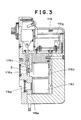
- Illustrated in Fig. 3 is the construction of the second radiometric density detector 116 of the sort which is used on various cigarette machines as mentioned hereinbefore.
- the radiant ray emitted from a radiation source 116a is transmitted to an ionization box 116b through a stick-like cigarette S.
- the ionization current which is produced in the ionization box 116b is reduced by a drop in incident radiation when the stick-like cigarette S has a high density, and increased by an increase in incident radiation when the cigarette S has a low density.
- a shutter 116c is provided between the radiation source 116a and cigarette S.
- Another radiation source 116d is provided in a position adjacent to the above-described radiation source 116a, the radiant ray from the radiation source 116d being transmitted to an ionization box 116f through a reference object 116e with a standard density to produce a reference ionization current in the ionization box 116f.
- Normally, negative and positive voltages are .applied to the ionization boxes 116b and 116f, respectively, so that the output of the amplifier 116g which is applied with the ionization currents of the two ionization boxes 116b and 116f becomes zero when the stick-like cigarette S has a standard density. That is to say, the output of the amplifier 116g becomes negative or positive depending upon the density of the stick-like cigarette S. Accordingly, the amplifier 116g produces an output signal corresponding to a deviation in density of the stick-like cigarette S from the standard density.
- Fig. 4 Shown in Fig. 4 is a control circuit for the device of the invention, in which the component parts common to Figs. 1 to 3 are designated by like reference characters.
- the tobacco T is sucked upwardly through the chimney 100 and adhered in a stratiform on the lower side of the perforated cigarette conveyer 103 which is located beneath the suction chamber 102.
- the tobacco T is transferred in the arrowed direction toward the trimmer 104 where excessive tobacco is shaved off by a trimming disc 104a.
- the tobacco is passed through the .first radiometric density detector 106. as indicated by broken line to measure its density. Namely, as described hereinbefore in connection with Fig.
- the radiant ray from the radiation source 106a is transmitted to the ionization box 106b through the tobacco T, and the ionization box 106b which is applied with a high voltage produces a weak ionization current as its output.
- This weak current is amplified by the amplifier 106i and, after addition of a standard signal from a standard signal generator 200, amplified again by an amplifier 202.
- the signal which is produced at the output terminal of the amplifier 202 is a voltage signal of a polarity and a level corresponding to the deviation of the actually measured density from the standard density.
- the radiant ray which is emitted from the radiation source 116a of the detector 116 is transmitted to the ionization box 106b through the stick-like cigarette S.
- a radiant ray from another radiation source 116d is transmitted to the ionization box 106f through a reference object 116e with a standard density. Since voltages of opposite polarities are applied to the ionization boxes 106b and 106f, a voltage signal of a polarity and a level corresponding to the deviation of the actually measured density of the stick-like cigarette S from the standard density appears at the output terminal of the amplifier 116g. This output signal of the amplifier 116g is amplified by the amplifier 204.
- the deviations in density of the stick-like cigarette S and the stratiform tobacco T are indicated by the output signals of the amplifiers 204 and 202, respectively. These two output signals should be basically the same but a slight difference occurs since fine tobacco shreds are sucked into the suction chamber 102 through the holes in the perforated conveyer 103 after the cut tobacco T leaving the first density detector 106.
- the output of the amplifier 204 is applied to an amplifier 20B which is also supplied with the output of the amplifier 202 after inversion through an amplifier 206.
- the amplifier 208 produces at its output terminal a signal proportional to the difference between the output signals of the first and second radiometric density detectors 106 and 116. If this signal is in a range between the preset voltage values from the voltage generators 210 and 212, comparators 214 and 216 both produce an output signal of low level, and, if not, one of the comparators 214 and 216 produces an output of high level and a signal of high level appears at the output terminal of an OR gate 218.
- the output signal of the OR gate which indicates an abnormal difference between the two radiometric density detectors can be used for stopping the operation of the machine cr to actuate an indicator. Accordingly, it becomes possible to guarantee an appropriate tobacco content for all of the cigarettes to be produced, and to prevent shipment of defective products which is detrimental to a cigarette manufacturer.
- the output of the amplifier 202 which represents the measured value of the first radiometric density detector 106 is added as a first signal to a second signal which is produced by integrating at an integrator 224 the outpat signal of the amplifier 204 which represents the measured value of the second radiometric density detector 116 followed by gain control through an amplifier 224.
- the output of the adder 226 is integrated by an integrator 22B and then amplified by an amplifier 230 before supply to an electrohydraulic servo valve 232.
- the electrohydraulic servo valve 232 selectively supplies the pressurized oil from a gear pump 234 to the upper and lower chambers of a cylinder 236 according to the applied voltage, thereby displacing a piston 238 upward or downward within the cylinder 236.
- the upward or downward movement of the piston 238 is transmitted to the trimming disc 104a of the trimmer L04 through a link 240, shaft 242, link 244 and connecting rod 246, to move the trimming disc 104a upward.or downward.
- the position of the trimming disc 104a is detected by a differential transformer 240, which is applied with a signal of several kHz from an oscillator 250 and has its center core connected to the piston 238 through the shaft 242 and like 240. Therefore, in response to the upward and downward movements of the piston 238, a corresponding signal appears at the output terminal of the differential transformer 248, and this signal is amplified by an amplifier 252.
- Half-wave portions of the output of the amplifier 252 are dropped off to the earth by a switch 254 which is operated by the output signal of an amplifier 250, and the remaining half-wave portions are flattened by a low pass filter 256, followed by DC amplification by an amplifier 258.
- the output of this amplifier 258 is applied to the adder 226 as a third input signal.
- the trimming disc 104a is lowered until the third input signal becomes equal to the sum of the first and second input signals.
- the polarity in the foregoing operation is inversed.
- the speed of operation can be varied by changing the integration speed of the integrator 228, and the extent of movement can be adjusted by altering the gain of the amplifier 230.
- the second signal which concerns the radiometric density detector 116 is a signal which is obtained by integrating the density signal by the integrator 222.
- the first signal which concerns the radiometric density detector 106 is a signal proportional to the density signal. Accordingly, when there is a difference between the first and second signals, the first signal may be dominant during a short time period, but the second signal is gradually increased by integration to a value which overwhelms the first signal. Therefore, the tobacco content is determined and controlled according to the first signal with respect to variations of a short period and according to the second signal with respect to variations of a long period.
- FIG. 5 Illustrated in Fig. 5 is a drive mechanism for the trimming disc 104a, wherein the piston 238 is alidable up and down in the cylinder 236 which is fixedly mounted on an outer casing.
- the piston 238 is pushed down when pressurized oil is introduced into a cylinder chamber 236a through a pipe 300.
- the oil in the cylinder chamber 236b on the opposite side of the piston 238 is drained into a tank through a return pipe 304.
- a filter 308 is provided at the outlet end of the return pipe 304.
- the above-described hydraulic system is maintained at a preset oil pressure.
- an oil pressure exceeding the preset pressure level is applied by the gear pump, it is drained to the tank through a pipe 312 branched from a pipe 310 leading from the gear pump 234 to the electrohydraulic servo valve 232 and the filter 308, by operation of a relief valve 314.
- the pressure in the hydraulic system is preset by adjustment through a pressure adjusting screw 318.
- the upward and downward movements of the piston 238 are picked up by a connecting rod 320 whioh is pivotally connected to the piston 238.
- the other end of the connecting rod 320 is pivotally connected to a link 240, so that upward and downward movement of the piston 238 cause the link 240 to rock up and down along with the shaft 242.
- the link 240 is securely fixed to the shaft 242 which is pivotally supported on the outer casing 306.
- the rocking movement which is transmitted to the shaft 242 through a link 244 which is fixed to the end of the shaft 24.2 to move vertically up and down a connecting shaft 236 which is pivotally supported at the other end of the arm.
- the trimming disc 104a is moved up and down by the upward and downward movements of the connecting shaft 246.
- link 330 Secured to the other end of the shaft 242 is a link 330 which is rockable upon rotation of the shaft 242. Attached to the link 330 is a link 332 which is moved up and down by upward and downward rocking movements of the link 330.
- the link 332 is fixed to a center core of the differential transformer 248 to move the core up and down along with the link 332.
- the differential transformer 248 is adapted to produce a positive voltage when the core is moved upward and a negative voltage when the core is moved downward in proportion to the distance of movement.
- the differential transformer 248 is arranged to produce a positive voltage when the connecting shaft 246 is moved upward and a negative voltage when moved downward.
- the reference numeral 336 denotes a motor which is connected to the gear pump 234 through a universal joint 338.
- the foregoing embodiment is arranged to check whether or not the difference between the first and second radiometric density detectors 106 and 116 is within a predetermined range, it is also possible to apply the same operation to the output of each detector.
- the tobacco content control device of the invention is arranged to catch a trouble of a radiometric density detector by detecting outrun of the output signal of the density detector from a predetermined range. Therefore, it becomes possible to stop the cigarette machine automatically when the radiometric density detector fails to measure the density of tobacco contents correctly due to a certain trouble, precluding a frightful situation, i.e., production of an enormous amount of defective cigarettes, without necessitating frequent periodic sampling of cigarettes by an operator.
Landscapes
- Health & Medical Sciences (AREA)
- General Health & Medical Sciences (AREA)
- Toxicology (AREA)
- Manufacturing Of Cigar And Cigarette Tobacco (AREA)
Abstract
Description
- This invention relates to a device for controlling. contents of tobacco on a cigarette manufacturing machine, and more particularly to a tobacco content control device which is capable of controlling tobacco contents constantly to a predetermined amount to guarantee production of cigarettes with uniform tobacco contents.
- Reduction of production cost is a matter of utmost importance to a manufacturer of cigarettes for increasing profits, and to this end various efforts have thus far been devoted.
- One way of cutting the production cost is to enhance the productivity of a cigarette machine, and in this regard the technical developments have almost reached a stage where a single cigarette machine can produce as many as 8000 cigarettes per minute.
- Another way of cutting the production cost is to reduce the irregularities in tobacco contents of the individual cigarettes to be produced. Namely, in view of recent increases in leaf tobacco cost, a vast profit can be made by slightly reducing the tobacco contents of the cigarettes. However unduly large reductions of the tobacco contents make it difficult to retain required quality. Accordingly, the approach generally taken in the production of cigarettes has been to measure the irregularities in weight of tobacco contents of cigarettes to check for deviations from a standard weight, determining a target value by adding a proportional amount of tobacco to a minimum weight of tobacco which is passable in terms of quality.
- In other words, reduction of irregularities in weight of the tobacco contents leads to minimization of the target value. This is why the cigarette manufacturers have been paying great efforts in reducing irregularities in weight of the tobacco contents of cigarettes.
- In order to reduce irregularities in tobacco contents, it is important to keep a cigarette machine in good maintenance to preclude liable movements of worn-out mechanical parts. However, the best measure is to add a tobacco content control device of high quality to the cigarette manufacturing machine, and various devices have been proposed in this connection.
- For example, Tapanese Patent Appln. Pub. No. 38-18750 discloses a method of controlling the tobacco content on the basis of air permeability, utilizing correlation between the weight of a tobacco content and its air permeability. However, this method is influenced by variations in the suction pressure and the particle size composition of tobacco, which tend to disturb the pre-established correlation between the weight and air permeability of the tobacco content, failing to reduce the irregularities in tobacco content to any significant degree.
- Disclosed in U.S. Patent Nos. 2,937,280 and 2,861,683 are electrostatic capacity methods based on correlation between a tobacco content and its electrostatic capacity. These methods are, however, susceptible to influences of moisture contents in tobacco and temperature which bias the correlation between the tobacco content and electrostatic capacity. Accordingly, they barely contribute to the reduction of irregularities in tobacco contents to any substantial degree, and have almost no possibility of practical application.
- There has been another method which utilizes the correlation between a radiant ray, especially beta ray emitted from strontium 90, and the density of tobacco, controlling the tobacco contents on the basis of the transmission factor of the radiant ray. Since there is extremely reliable correlation between the transmissibility of radiant ray and tobacco content, this method is adopted for most of current cigarette manufacturing machines, in spite of problems such as problems concerning safety in handing the radiant ray and drifts and inferior response of an amplifier in a subsequent stage due to weakness of the output current of an ionization box which serves as a detection means.
- The conventional tobacco content control device using a radiometric detector has a great defect that, in case of a trouble in a component part of the radiation detector, the measured value of transmissibility of a radiant ray which represents the tobacco content is-varied irrespective of the actual tobacco content, as a result causing variations in the tobacco contents of cigarettes to be produced. Although a radiometric detector is handled more carefully than ordinary instruments, troubles unavoidably occur to its component parts, including, for example, breakage of a foil of a metal like Lilanium which is adhered to a portion whore a cigarette is irradiated by an incident radiant ray, leakage of gas from an ionization box which converts the intensity of transmitted radiation into a variation in electric current, and drifts of an amplifier which amplifies the weak current output of the ionization box. These troubles take place all of a sudden or gradually, so that it is necessitated to check from time to time the average weight of the cigarettes being produced, namely, the target value of the control. Normally, a suitable numeral of cigarettes are weighed every ten minutes or so to guarantee a certain average weight. However, these operations are wasteful for a cigarette manufacturer and regard as a cause which lowers the labor productivity and which raises the production cost of cigarettes.
- It is therefore an object of the present invention to provide a tobacco content control device for a cigarette manufacturing machine, which device is adapted to detect a trouble in a radiometric density detector immediately to prevent production of cigarettes of defective quality.
- In order to achieve the just-mentioned objective, the present invention provides a tobacco content control device for cigarette manufacturing machines, including a radiometric density'detection means for irradiating tobacco being transferred along a predetermined path on a cigarette machine with a radiant ray and converting the intensity of radiation transmitted through the tobacco into an electric signal, controlling tobacco contents to a predetermined value according to the output signal of the radiometric density detection means, characterized in that the control device comprises: voltage generating means for producing two - voltage signals indicative of upper and lower limits of a predetermined range; and comparison means adapted to compare the output signal of the radiometric density detection means with the voltage signals and to produce an output signal when the predetermined signal is outrun; and means for informing abnormality of the radiometric detection means in response to the output signal of the comparison means.
- The above and other objects, features and advantages of the invention will become apparent from the following description and appended claims, taken in conjunction with the accompanying drawings which show by way of example some preferred embodiments of the invention.
- In the accompanying drawings:
- Fig. 1 is a schematic front view of a cigarette machine incorporating a tobacco content control device according to the present invention;
- Figs. 2 and 3 are enlarged sectional views showing part of the control device of Fig. 1;
- Fig. 4 is an electric circuit diagram of the control device according to the invention; and
- Fig. 5 is a schematic perspective view showing in detail other components of the control device of Fig. 1.
- Referring to Fig. 1, there is schematically shown a cigarette machine employing a tobacco content control device embodying the present invention, wherein cut tobacco is sucked upward through a
chimney 100 and adhered by suction to the lower side of a perforatedcigarette conveyer 103 which is located beneath asuction chamber 102. The adhered tobacco layer is transferred to the left in the drawing toward atrimmer 104 which regulates the tobacco layer into a suitable thickness. The stratiform tobacco layer with a regulated thickness is passed through a firstradiometric density detector 106 to measure its density, and then transferred onto and rolled in cigarette paper, which is fed from apaper roll 108 and stacked on acloth tape 110, glueing the cigarette paper by aglue applicator 112 and drying the glued portions by aheater 114 to form a stick-like cigarette. The thus formed stick-like cigarette is passed through a secondradiometric density detector 116 to check its density and cut into cigarettes of unit lengths by acutter 118. The cigarettes from the cutter is trans- ferred to a tray by a conveyer which is not shewn. - Shown in Fig. 2 is the construction of the first
radiometric density detector 106, including aradiation cource 106a which emits a radiant ray, and anioniration box 106b which receives the radiant ray from theradiation source 106a. Theradiation source 106a andionization box 106b are located at a predetermined distance from each other and confronted through aperture windows 106c and 106d which are formed in the respective casings.Thin metal films 106e and 106f, preferably consisting of titanium foils, are adhered to the aperture windows 106c and 106d. Provided between thethin metal films 106e and 106f is a channel for passing the trimmed tobacco T on theperforated conveyer 103. A shutter 106g is provided between the radiation source 106a and aperture window 106c to prevent leakage of radiation to the outside when it is unnecessary. - With the foregoing construction, when the shutter 106g is open, the radiant ray emitted from the
radiation source 106a is transmitted through thethin metal foil 106e of the aperture window 106c and the tobacco layer T and received by theionization box 106h through the thin metal film 106f of the aperture window 106d. The outer periphery of theionization box 106b is maintained at a high potential by a highvoltage power supply 106h, so that a small current is supplied to anamplifier 106i when the tobacco layer T has a high density and on the contrary a large current is supplied when the tobacco density is low. Namely, theamplifier 106i produces an output signal indicative of the density of the stratiform tobacco layer before rolling into the cigarette paper. - Illustrated in Fig. 3 is the construction of the second
radiometric density detector 116 of the sort which is used on various cigarette machines as mentioned hereinbefore. The radiant ray emitted from aradiation source 116a is transmitted to anionization box 116b through a stick-like cigarette S. The ionization current which is produced in theionization box 116b is reduced by a drop in incident radiation when the stick-like cigarette S has a high density, and increased by an increase in incident radiation when the cigarette S has a low density. A shutter 116c is provided between theradiation source 116a and cigarette S. - Another
radiation source 116d is provided in a position adjacent to the above-describedradiation source 116a, the radiant ray from theradiation source 116d being transmitted to an ionization box 116f through areference object 116e with a standard density to produce a reference ionization current in the ionization box 116f. Normally, negative and positive voltages are .applied to theionization boxes 116b and 116f, respectively, so that the output of theamplifier 116g which is applied with the ionization currents of the twoionization boxes 116b and 116f becomes zero when the stick-like cigarette S has a standard density. That is to say, the output of theamplifier 116g becomes negative or positive depending upon the density of the stick-like cigarette S. Accordingly, theamplifier 116g produces an output signal corresponding to a deviation in density of the stick-like cigarette S from the standard density. - Shown in Fig. 4 is a control circuit for the device of the invention, in which the component parts common to Figs. 1 to 3 are designated by like reference characters.
- As described hereinbefore in connection with Fig. 1, the tobacco T is sucked upwardly through the
chimney 100 and adhered in a stratiform on the lower side of the perforatedcigarette conveyer 103 which is located beneath thesuction chamber 102. The tobacco T is transferred in the arrowed direction toward thetrimmer 104 where excessive tobacco is shaved off by a trimmingdisc 104a. Thereafter, the tobacco is passed through the .firstradiometric density detector 106. as indicated by broken line to measure its density. Namely, as described hereinbefore in connection with Fig. 5, the radiant ray from theradiation source 106a is transmitted to theionization box 106b through the tobacco T, and theionization box 106b which is applied with a high voltage produces a weak ionization current as its output. This weak current is amplified by theamplifier 106i and, after addition of a standard signal from astandard signal generator 200, amplified again by anamplifier 202. The signal which is produced at the output terminal of theamplifier 202 is a voltage signal of a polarity and a level corresponding to the deviation of the actually measured density from the standard density. Thereafter, the tobacco T is rolled in cigarette paper and glue is applied to the paper to form a stick-like cigarette S. This stick-like cigarette S is then passed through the secondradiometric density detector 116. - As described hereinbefore with reference to Fig. 3, the radiant ray which is emitted from the
radiation source 116a of thedetector 116 is transmitted to theionization box 106b through the stick-like cigarette S. On the other hand, a radiant ray from anotherradiation source 116d is transmitted to the ionization box 106f through areference object 116e with a standard density. Since voltages of opposite polarities are applied to theionization boxes 106b and 106f, a voltage signal of a polarity and a level corresponding to the deviation of the actually measured density of the stick-like cigarette S from the standard density appears at the output terminal of theamplifier 116g. This output signal of theamplifier 116g is amplified by theamplifier 204. - In this manner, the deviations in density of the stick-like cigarette S and the stratiform tobacco T are indicated by the output signals of the
amplifiers suction chamber 102 through the holes in theperforated conveyer 103 after the cut tobacco T leaving thefirst density detector 106. - For the purpose of obtaining the difference from the
output 202, the output of theamplifier 204 is applied to an amplifier 20B which is also supplied with the output of theamplifier 202 after inversion through anamplifier 206. Thus, theamplifier 208 produces at its output terminal a signal proportional to the difference between the output signals of the first and secondradiometric density detectors voltage generators comparators comparators OR gate 218. - The output signal of the OR gate which indicates an abnormal difference between the two radiometric density detectors can be used for stopping the operation of the machine cr to actuate an indicator. Accordingly, it becomes possible to guarantee an appropriate tobacco content for all of the cigarettes to be produced, and to prevent shipment of defective products which is detrimental to a cigarette manufacturer.
- By an
adder 226, the output of theamplifier 202 which represents the measured value of the firstradiometric density detector 106 is added as a first signal to a second signal which is produced by integrating at anintegrator 224 the outpat signal of theamplifier 204 which represents the measured value of the secondradiometric density detector 116 followed by gain control through anamplifier 224. - The output of the
adder 226 is integrated by an integrator 22B and then amplified by anamplifier 230 before supply to anelectrohydraulic servo valve 232. Theelectrohydraulic servo valve 232 selectively supplies the pressurized oil from agear pump 234 to the upper and lower chambers of acylinder 236 according to the applied voltage, thereby displacing apiston 238 upward or downward within thecylinder 236. The upward or downward movement of thepiston 238 is transmitted to thetrimming disc 104a of the trimmer L04 through alink 240,shaft 242, link 244 and connectingrod 246, to move thetrimming disc 104a upward.or downward. - The position of the
trimming disc 104a is detected by adifferential transformer 240, which is applied with a signal of several kHz from anoscillator 250 and has its center core connected to thepiston 238 through theshaft 242 and like 240. Therefore, in response to the upward and downward movements of thepiston 238, a corresponding signal appears at the output terminal of thedifferential transformer 248, and this signal is amplified by anamplifier 252. Half-wave portions of the output of theamplifier 252 are dropped off to the earth by aswitch 254 which is operated by the output signal of anamplifier 250, and the remaining half-wave portions are flattened by alow pass filter 256, followed by DC amplification by anamplifier 258. The output of thisamplifier 258 is applied to theadder 226 as a third input signal. - With the foregoing arrangement, when the sum of the first and second input signals of the
adder 226 is positive, that is to say, when the tobacco content is deficient, a voltage appears at the output terminal of theadder 226, gradually increasing the output of theintegrator 228 in a negative direction. As a result,.the output of theamplifier 230 is increased in a positive direction, so that theelectrohydraulic servo valve 232 slowly changes the flow of oil to push up thepiston 238, lowering thetrimming disc 104a through thelink 240,shaft 242, link 244 and connectingrod 246 to increase the tobacco content. Simultaneously, the third input signal of theadder 226 is increased by the output signal of thedifferential transformer 248.. Accordingly, thetrimming disc 104a is lowered until the third input signal becomes equal to the sum of the first and second input signals. In case the tobacco content is excessive, the polarity in the foregoing operation is inversed. The speed of operation can be varied by changing the integration speed of theintegrator 228, and the extent of movement can be adjusted by altering the gain of theamplifier 230. - Thus, the second signal which concerns the
radiometric density detector 116 is a signal which is obtained by integrating the density signal by theintegrator 222. On the other hand, the first signal which concerns theradiometric density detector 106 is a signal proportional to the density signal. Accordingly, when there is a difference between the first and second signals, the first signal may be dominant during a short time period, but the second signal is gradually increased by integration to a value which overwhelms the first signal. Therefore, the tobacco content is determined and controlled according to the first signal with respect to variations of a short period and according to the second signal with respect to variations of a long period. - Illustrated in Fig. 5 is a drive mechanism for the
trimming disc 104a, wherein thepiston 238 is alidable up and down in thecylinder 236 which is fixedly mounted on an outer casing. Thepiston 238 is pushed down when pressurized oil is introduced into acylinder chamber 236a through apipe 300. At this time, the oil in thecylinder chamber 236b on the opposite side of thepiston 238 is drained into a tank through areturn pipe 304. Similarly, when pressurized oil is introduced into thecylinder chamber 236b to push up thepiston 238, the oil in theopposite cylinder chamber 236a is drained into the tank through thereturn pipe 304. Afilter 308 is provided at the outlet end of thereturn pipe 304. - The above-described hydraulic system is maintained at a preset oil pressure. In case an oil pressure exceeding the preset pressure level is applied by the gear pump, it is drained to the tank through a
pipe 312 branched from apipe 310 leading from thegear pump 234 to theelectrohydraulic servo valve 232 and thefilter 308, by operation of arelief valve 314. The pressure in the hydraulic system is preset by adjustment through apressure adjusting screw 318. - The upward and downward movements of the
piston 238 are picked up by a connectingrod 320 whioh is pivotally connected to thepiston 238. The other end of the connectingrod 320 is pivotally connected to alink 240, so that upward and downward movement of thepiston 238 cause thelink 240 to rock up and down along with theshaft 242. Thelink 240 is securely fixed to theshaft 242 which is pivotally supported on theouter casing 306. The rocking movement which is transmitted to theshaft 242 through alink 244 which is fixed to the end of the shaft 24.2 to move vertically up and down a connectingshaft 236 which is pivotally supported at the other end of the arm. Thetrimming disc 104a is moved up and down by the upward and downward movements of the connectingshaft 246. - Secured to the other end of the
shaft 242 is alink 330 which is rockable upon rotation of theshaft 242. Attached to thelink 330 is alink 332 which is moved up and down by upward and downward rocking movements of thelink 330. Thelink 332 is fixed to a center core of thedifferential transformer 248 to move the core up and down along with thelink 332. - For instance, the
differential transformer 248 is adapted to produce a positive voltage when the core is moved upward and a negative voltage when the core is moved downward in proportion to the distance of movement. In the particular embodiment shown, thedifferential transformer 248 is arranged to produce a positive voltage when the connectingshaft 246 is moved upward and a negative voltage when moved downward. - The
reference numeral 336 denotes a motor which is connected to thegear pump 234 through auniversal joint 338. - Although the foregoing embodiment is arranged to check whether or not the difference between the first and second
radiometric density detectors - As clear from the foregoing description, the tobacco content control device of the invention is arranged to catch a trouble of a radiometric density detector by detecting outrun of the output signal of the density detector from a predetermined range. Therefore, it becomes possible to stop the cigarette machine automatically when the radiometric density detector fails to measure the density of tobacco contents correctly due to a certain trouble, precluding a frightful situation, i.e., production of an enormous amount of defective cigarettes, without necessitating frequent periodic sampling of cigarettes by an operator.
Claims (3)
Applications Claiming Priority (2)
| Application Number | Priority Date | Filing Date | Title |
|---|---|---|---|
| JP59090257A JPS60234575A (en) | 1984-05-08 | 1984-05-08 | Content tobacco amount controller of cigarette producing machine |
| JP90257/84 | 1984-05-08 |
Publications (2)
| Publication Number | Publication Date |
|---|---|
| EP0160800A2 true EP0160800A2 (en) | 1985-11-13 |
| EP0160800A3 EP0160800A3 (en) | 1988-07-27 |
Family
ID=13993438
Family Applications (1)
| Application Number | Title | Priority Date | Filing Date |
|---|---|---|---|
| EP85102176A Withdrawn EP0160800A3 (en) | 1984-05-08 | 1985-02-27 | Device for controlling contents of tabacco on cigarette machine |
Country Status (3)
| Country | Link |
|---|---|
| US (1) | US4638817A (en) |
| EP (1) | EP0160800A3 (en) |
| JP (1) | JPS60234575A (en) |
Cited By (2)
| Publication number | Priority date | Publication date | Assignee | Title |
|---|---|---|---|---|
| US6062226A (en) * | 1996-06-13 | 2000-05-16 | Japan Tobacco Inc. | Cigarette manufacturing apparatus |
| US11178901B2 (en) | 2015-04-09 | 2021-11-23 | Hauni Maschinenbau Gmbh | Suction belt conveyor and rod-forming machine of the tobacco processing industry, and use and method for measuring material properties of a material rod of the tobacco processing industry |
Families Citing this family (5)
| Publication number | Priority date | Publication date | Assignee | Title |
|---|---|---|---|---|
| JPS63112973A (en) * | 1986-10-31 | 1988-05-18 | 日本たばこ産業株式会社 | Content tobacco control apparatus of cigarette manufacturing machine |
| DE3801115C2 (en) * | 1987-01-31 | 1996-10-17 | Hauni Werke Koerber & Co Kg | Method and device for determining the density of a fiber strand of the tobacco processing industry |
| DE10117081A1 (en) * | 2001-04-06 | 2002-10-10 | Hauni Maschinenbau Ag | Device and method for generating a statement about the property (s) of a fiber strand |
| ITBO20030130A1 (en) * | 2003-03-10 | 2004-09-11 | Gd Spa | METHOD OF CONTROL OF AN AUTOMATIC MACHINE FOR THE PROCESSING |
| CN112099393A (en) * | 2020-08-19 | 2020-12-18 | 张家口卷烟厂有限责任公司 | System and method for monitoring operation and judging abnormality of cigarette machine equipment |
Family Cites Families (8)
| Publication number | Priority date | Publication date | Assignee | Title |
|---|---|---|---|---|
| GB945839A (en) * | 1959-07-18 | 1964-01-08 | Korber Kurt | Method and apparatus for producing a continuous tobacco rod |
| DE1920732A1 (en) * | 1969-04-24 | 1970-11-12 | Hauni Werke Koerber & Co Kg | Method and device for forming a signal corresponding to the variation in the density of a continuous rod of tobacco or filter |
| US3604429A (en) * | 1969-10-03 | 1971-09-14 | Industrial Nucleonics Corp | Cigarette-dense-end-measuring method and apparatus |
| US3604430A (en) * | 1969-11-07 | 1971-09-14 | Industrial Nucleonics Corp | Cigarette dense end measuring and controlling apparatus |
| JPS5195198A (en) * | 1975-02-10 | 1976-08-20 | Shigaretsutoseizoki ni okeru nakamitabakoryo no seigyosochi | |
| DE2545416C2 (en) * | 1975-10-10 | 1985-09-19 | Hauni-Werke Körber & Co KG, 2050 Hamburg | Method and device for forming a cigarette rod |
| GB1580258A (en) * | 1977-03-31 | 1980-11-26 | Molins Ltd | Cigarette weight control systems |
| DE3345608A1 (en) * | 1983-02-04 | 1984-08-09 | Hauni-Werke Körber & Co KG, 2050 Hamburg | METHOD AND DEVICE FOR MAKING ROD-SHAPED ITEMS OF THE TOBACCO-PROCESSING INDUSTRY |
-
1984
- 1984-05-08 JP JP59090257A patent/JPS60234575A/en active Granted
-
1985
- 1985-02-25 US US06/705,314 patent/US4638817A/en not_active Expired - Lifetime
- 1985-02-27 EP EP85102176A patent/EP0160800A3/en not_active Withdrawn
Cited By (2)
| Publication number | Priority date | Publication date | Assignee | Title |
|---|---|---|---|---|
| US6062226A (en) * | 1996-06-13 | 2000-05-16 | Japan Tobacco Inc. | Cigarette manufacturing apparatus |
| US11178901B2 (en) | 2015-04-09 | 2021-11-23 | Hauni Maschinenbau Gmbh | Suction belt conveyor and rod-forming machine of the tobacco processing industry, and use and method for measuring material properties of a material rod of the tobacco processing industry |
Also Published As
| Publication number | Publication date |
|---|---|
| US4638817A (en) | 1987-01-27 |
| EP0160800A3 (en) | 1988-07-27 |
| JPH0131873B2 (en) | 1989-06-28 |
| JPS60234575A (en) | 1985-11-21 |
Similar Documents
| Publication | Publication Date | Title |
|---|---|---|
| EP0160800A2 (en) | Device for controlling contents of tabacco on cigarette machine | |
| US6020969A (en) | Cigarette making machine including band inspection | |
| EP3341703B1 (en) | Holmium oxide glasses as calibration standards for near infrared moisture sensors | |
| US9441961B2 (en) | System and method for correcting caliper measurements of sheet products in sheet manufacturing or processing systems | |
| US5865059A (en) | Non-contact thickness gauge for non-metallic materials in the form of film, foil, tape and the like | |
| US4019131A (en) | Method and apparatus for measuring the shape of the wavy edges of metal strips using a detection coil controlled to track the strip edge | |
| US20050096202A1 (en) | Device for the simultaneous, continuous measurement and regulation of the acetate and triacetine level in filter rods of the tobacco-processing industry | |
| US3851175A (en) | Moisture gauge with opacity type compensation | |
| US4836221A (en) | Device for controlling contents of tobacco on cigarette manufacturing machine | |
| EP0949174B1 (en) | A method and a unit for feeding a strip of sheet material | |
| JPS6112672B2 (en) | ||
| US4300049A (en) | Dynamically standardized radiant energy method and apparatus for plural channel gain independent material property measurement | |
| US5014288A (en) | X-ray coating weight controller and sensor | |
| JPH06197746A (en) | Method and device for inspection to identify loose end of cigaret | |
| US4888977A (en) | Method of ascertaining the rate of fluid flow through the ventilation zones of rod-shaped articles of the tobacco processing industry | |
| JPH0131872B2 (en) | ||
| US4537206A (en) | Apparatus for perforating and testing the permeability of running webs of cigarette paper or the like | |
| US4860772A (en) | Method of and apparatus for making a rod of fibrous material | |
| EP0339250A1 (en) | A device for controlling the content of tobacco on a cigarette manufacturing machine | |
| US4920987A (en) | Device for controlling the content of tobacco on a cigarette manufacturing machine | |
| US4962517A (en) | Automatic X-ray correction device | |
| US4269201A (en) | Cigarette weight control systems | |
| US6173716B1 (en) | Method and apparatus for inspecting cigarette density | |
| EP0716303B1 (en) | A system related apparatus for the calibration of a sensor for moisture measurement on sheet, tape or film materials | |
| CA1085020A (en) | Roller mill performance monitoring by density sensing |
Legal Events
| Date | Code | Title | Description |
|---|---|---|---|
| PUAI | Public reference made under article 153(3) epc to a published international application that has entered the european phase |
Free format text: ORIGINAL CODE: 0009012 |
|
| AK | Designated contracting states |
Designated state(s): DE GB IT |
|
| RAP1 | Party data changed (applicant data changed or rights of an application transferred) |
Owner name: JAPAN TOBACCO INC. |
|
| PUAL | Search report despatched |
Free format text: ORIGINAL CODE: 0009013 |
|
| AK | Designated contracting states |
Kind code of ref document: A3 Designated state(s): DE GB IT |
|
| 17P | Request for examination filed |
Effective date: 19880826 |
|
| 17Q | First examination report despatched |
Effective date: 19900215 |
|
| STAA | Information on the status of an ep patent application or granted ep patent |
Free format text: STATUS: THE APPLICATION HAS BEEN WITHDRAWN |
|
| 18W | Application withdrawn |
Withdrawal date: 19910516 |
|
| R18W | Application withdrawn (corrected) |
Effective date: 19910516 |
|
| RIN1 | Information on inventor provided before grant (corrected) |
Inventor name: OKUMOTO, YUTAKA |