EP0160832A2 - Dispositif de guidage proportionnel d'un ruban encreur pour imprimantes à impact - Google Patents
Dispositif de guidage proportionnel d'un ruban encreur pour imprimantes à impact Download PDFInfo
- Publication number
- EP0160832A2 EP0160832A2 EP85103927A EP85103927A EP0160832A2 EP 0160832 A2 EP0160832 A2 EP 0160832A2 EP 85103927 A EP85103927 A EP 85103927A EP 85103927 A EP85103927 A EP 85103927A EP 0160832 A2 EP0160832 A2 EP 0160832A2
- Authority
- EP
- European Patent Office
- Prior art keywords
- ribbon
- character
- printed
- characters
- column
- Prior art date
- Legal status (The legal status is an assumption and is not a legal conclusion. Google has not performed a legal analysis and makes no representation as to the accuracy of the status listed.)
- Granted
Links
Images



Classifications
-
- B—PERFORMING OPERATIONS; TRANSPORTING
- B41—PRINTING; LINING MACHINES; TYPEWRITERS; STAMPS
- B41J—TYPEWRITERS; SELECTIVE PRINTING MECHANISMS, i.e. MECHANISMS PRINTING OTHERWISE THAN FROM A FORME; CORRECTION OF TYPOGRAPHICAL ERRORS
- B41J35/00—Other apparatus or arrangements associated with, or incorporated in, ink-ribbon mechanisms
- B41J35/20—Ink-ribbon shifts, e.g. for exposing print, for case-shift adjustment, for rendering ink ribbon inoperative
-
- B—PERFORMING OPERATIONS; TRANSPORTING
- B41—PRINTING; LINING MACHINES; TYPEWRITERS; STAMPS
- B41J—TYPEWRITERS; SELECTIVE PRINTING MECHANISMS, i.e. MECHANISMS PRINTING OTHERWISE THAN FROM A FORME; CORRECTION OF TYPOGRAPHICAL ERRORS
- B41J35/00—Other apparatus or arrangements associated with, or incorporated in, ink-ribbon mechanisms
- B41J35/04—Ink-ribbon guides
- B41J35/10—Vibrator mechanisms; Driving gear therefor
- B41J35/12—Vibrator mechanisms; Driving gear therefor adjustable, e.g. for case shift
Definitions
- the present invention relates to a method of and apparatus for effecting ribbon lift in impact printers, which ribbon lift is proportional to the height of the character being printed to thereby maximize the ribbon usage.
- a method and apparatus for effecting ribbon lift in impact printers which ribbon lift is proportional to the height of the character being printed. This is accomplished by dividing the maximum height character box into a plurality of zones, for example five such zones corresponding to underline, descender, main, ascender and overscore. By knowing the base line of a character that is to be printed as well as the number of zones the character covers (its height) and the last used place on the ribbon that was printed, a maximum number of characters may be stacked in a vertical column on the ribbon.
- a maximum number of characters may be obtained from the ribbon by combining proportional ribbon lift with proportional ribbon feed.
- Numerous techniques may be employed to increase the number of characters permitted on the print ribbon. For example, the simplest technique would permit the printing on multiple levels (lifts) of, for example, an underline. Other, larger letters may be printed employing a multiple-increment ribbon lift prior to ribbon feed. Where the lift is dependent on character height, true proportionality of ribbon lift to the character(s) being printed is obtained.
- the character position on, for example, a printwheel, its height and width are all taken into consideration in determining proper ribbon lift to expose the printwheel character to a fresh section of ribbon without wasting ribbon, or leaving substantial portions of unused and virgin ribbon, to thereby increase the number of characters that may be printed utilizing a single ribbon, such as a correctable film ribbon.
- a portion 10 of the electrical control means for a typical impact printer incorporating the method and apparatus of the present invention is illustrated therein.
- the term printer encompasses both the conventional 'line' printer, as well as the printer portion of a typewriter.
- the control portion of the printer will include an input means 11, such as keyboard in the instance of a typewriter, or a computer connected to storage devices, such as disk or tape.
- a buffer 12 which permits the storage of input characters in a queue along with control commands for appropriate operation thereon by a microprocessor 13.
- a block of random access memory 14 which may be used for standard purposes (variable storage, command storage, and character storage) as the case may be.
- the control portion 10 also includes a read only memory 15 which is connected to the microprocessor 13, and contains appropriate algorithms for controlling the text management function of the printer. These algorithms are loaded, as called for by the microprocessor 13 and the controlling information contained in ROM 15 so as to control, as through an output line 16, various moving parts of the printer.
- ribbon lift electronics 17 and ribbon feed electronics 18 for controlling stepping motors and the like (hereinafter discussed relative to Figs. 2A and 2B) may be conventional;
- the text management function may appear anywhere in the system.
- the input means 11 includes a computer
- the management of the text may be performed in the computer itself with raw commands being applied to the microprocessor 13 for calling up pure printer control commands and character indicia as described hereinafter.
- the input means may include other microprocessors similar to the printer control portion 10 which serves to monitor the keys on the keyboard of the typewriter so as to request, through the buffer 12, printer control portion 10 to print a graphic.
- microprocessor 13 in response to the command that is passed to the microprocessor 13, its associated RAM 14 and ROM 15, microprocessor 13 looks up, in a character characteristic table in the ROM 15, the base line, height, width etc. of the particular graphic (character) that is to be printed. Realistically, other parameters are held in the character characteristic table in the ROM 15, for example hammer velocity and wheel petal number of the graphic that is to be printed.
- the width of the character may also be passed to an essentially conventional escapement control component so that a carrier upon which the printing implements are mounted may escape.
- the hammer velocity may also be passed to a hammer control component so that the petal may be struck with the correct force.
- the present invention relates to the passing of certain character characteristics from the ROM 15, such as character width, height, base line, to control the ribbon lift in accordance with the method charted in Fig. 5 to effect desired ribbon control.
- the present invention is particularly useful with impact printers, for example daisy wheel printers, but may also be useful with printers of a thermal nature wherein heat causes flow of the ink from the ribbon onto paper or the like, and with which it is desirable to maximize the use of the ribbon.
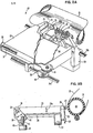
- this printer includes a platen 21 about which print receiving media such as paper 22 is fed to permit indicia (characters etc.) to be printed thereon as through ink ribbon 23 passing intermediate platen 21 and print petals 24 of a print wheel (daisy wheel) 25.
- the printwheel 25 has a hub or a central portion 26 (Fig. 2B) which is connected to a stepping motor 27 for control by the printer control portion 10.
- a print hammer 28 is energized, (by means not shown, for example a solenoid) to effect impact of the petal against the ribbon 23 and therefore against the paper 22.
- the implements of printing in the illustrated instance the print wheel 25, ribbon 23 and hammer 28, are all mounted on a print carrier 30 for translation, in the present instance on shafts 31a and 31b between the side frames (not shown) of the machine. Also mounted on the carrier 30 as part of the implements of printing are means for holding a supply of ribbon 23, in the illustrated instance a ribbon cartridge 33. It should be understood, however, that the ribbon cartridge may be positioned off the carrier. In this type of implementation, however, separate means must be employed to effect elevation and depression of the ribbon 23 intermediate the print wheel 25 and paper-carrying platen 21.
- the cartridge 33 may include a depending cassette or the like 34 which places correction ribbon or tape 35 intermediate the print wheel 25 and the paper 22 for correction purposes in a well known manner.
- the cartridge 33 with ink ribbon 23 may be elevated and lowered as shown by the arrow 33a in Fig. 2B to position the ribbon properly with respect to the indicia-carrying print petal 24 to permit impact of the indicia, through the ribbon 23 and onto the paper 22.
- the cartridge 33 may be positioned on a platform or the like 36 (Fig. 2B) which forms part of the carrier 30, and which may be elevated and lowered to effect elevation and depression of the cartridge 33 and thus the print ribbon 23.
- a platform or the like 36 FIG. 2B
- This is accomplished, in the illustrated instance, by an axle 37 which is journaled through brackets 38 (Fig. 2B) connected to the depending cartridge support means or platform 36.
- a gear segment 39 which includes teeth 40 thereon which mesh with a pinion gear 45 connected to the shaft 46 of a drive means, in the illustrated instance and preferred embodiment, a stepping motor 47.
- a second drive means in the illustrated instance and in the preferred embodiment, a stepping motor 49, is connected through a pinion gear 50 to a drive gear 51.
- This coupling effects, in a predetermined rotation at a predetermined and preselected time, feed of the ribbon 23 so as to always expose a fresh portion of ribbon (longitudinally) opposite the print wheel.
- the drive for the stepping motors are under microprocessor 13 control and the associated electronics, i.e. 17 and 18 for ribbon lift and ribbon feed, respectively, may take any well known form, or may preferably be of the form disclosed in EP-A-116,112.
- a table in ROM 15 is accessed for the character to be printed and returns to the microprocessor a predetermined plurality of characteristics of the character to be printed.
- the RAM 14 in conjunction with a program in the microprocessor, keeps track of the position on the ribbon where one of the prior characters has been printed and adds to that track position a particular characteristic of the character to determine a new track print position. That new position is outputted from the microprocessor 13 to the ribbon lift (and/or feed) electronics 17 (18) to effect elevation (and, if appropriate, feed) of the ribbon to one of a multiple of predetermined positions so that an increased number of characters may be printed thereon.
- the characteristics of the indicia (characters) carried by the table in the ROM 15 classifies the portion 24A of petals 24 carrying the character thereon into five discrete zones numbered 1-5 and labeled in Fig. 4 as overscore (1), ascenders (2), main (3), descenders (4), and underscore (5).
- a second characteristic that is necessary for proportional ribbon lift is the height of a character and their zone.
- the letters and characters illustrated in Fig. 4, that is the graphics "a, b, g, _, O, - , b" each have a lower base line in the lowest zone in which they appear, and each have a height.
- the letter “a” has a base line in the center or main zone (3). It also has a character height of "1" and a character width of "5". (Width is placed as arbitrary units, in the present instance 0.423mm per unit of width. For example a “W is the widest character and has a width of 7 (2.96mm), while an “i” has a width of 3 (1.26mm))
- the character “b” has a base line still in the main zone (zone 3) but has an extension upwardly which passes into the ascender zone (zone 2) and thus has a height of two zones.
- the character “g”, while having a height of only two zones starts in the descender zone (zone 4). The remainder of the characters, with regard to height, width and baseline (zone*) may be read across the table.
- the ribbon may be thought of as being divided into a plurality of tracks.
- the ribbon is divided into 10 such tracks each having a height equal to the height of a single character zone.
- zones could be further divided and the number of tracks on a print ribbon could also be further increased.
- 10 such tracks have been found to be convenient and the division of the characters into 5 zones has also been found to be convenient.
- a character in zone 3 may be printed on track 5 of the ribbon.
- Fig. 5 shown therein is a flow chart of a program which may be utilized by the control portion 10 of the printer to effect proportional lift, and in the preferred embodiment also proportional feed of the print ribbon 23.
- POR turning the power on to the printer commonly called "Power-on-Reset” or POR
- a ribbon feed occurs to present a fresh "column" of ribbon 23 opposite the printwheel 25.
- certain variables employed in the program are initialized. Set forth below is a table of the variables, their meaning, and their initialized condition:
- the base line (character zone), height, and width of several characters are set forth in Fig. 4.
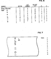
- the initial conditions are also exemplified in the table of Fig. 6.
- Fig. 6 the characters are treated as being printed in the order shown.
- One extra condition for the reader's benefit that is a column indicating relative lift is included. This column would indicate, with respect to Fig. 3A, the lift necessary to arrive from the previous lift position to the lift position marked in the column marked lift, and will indicate relative to Fig. 3A whether the ribbon must be lifted or depressed to reach a new lift position.
- the input means When the input means receives its first character to be printed, and in this example that is the character "a", the characteristics of that character are fetched from the ROM 15 and provided as an input as at 60 to the program (Fig. 5). As illustrated in Fig. 4, the initial input conditions for the character "a” are a base line or character zone of 3, a height H of 1 and, in the present instance, a width W of 5.
- the character count CC is incremented by 1 to keep a running count of the characters.
- the characters input are assumed to be those of Fig. 4, in the order that the first character is a lower case "a”.
- the new value of H for "a" is 1. This is added to the initialized value (1) of NXTTRK in block 61 so that the new value NXTTRK is 2.
- the value of NXTTRK is then tested as in decision 62 to determine whether the value of NXTTRK is less than or equal the number of tracks plus 1 (that is 11).
- the program is branched through node 63 into an algorithm in block 64 which determines the ribbon lift address, LA.
- the lift address LA is equal to 4 minus the base line (character zone) plus the value of NXTTRK.
- the lift address LA will be equal to 3.
- Fig. 3A opposite the legend "Lift Positions", and following up lift position 3, shows that the first character "a” which resides in character zone (3) will print at the uppermost track or track (1) of the ribbon. (See Fig. 7) It follows then that the relative lift is plus 3 from the initialized zero or visibility position of the ribbon.
- the microprocessor 13 places an output on line 16 which causes the electronics 17 to effect a ribbon lift to the position illustrated in Fig. 3A wherein track 1 of the ribbon is opposite zone (3) of the printwheel petal.
- decision 65 the maximum width (which was set initially to zero) is tested against the width of the character, and in the illustrated instance since the maximum width was zero, which is less than W, the outputs through the yes branch and sets the maximum width (MAXW) equal to the width W or 5.
- the output of this logic block 66 is then provided through node 67 and the microprocessor 13 may output an order or command to the printer to effect printing.
- the table of Fig. 4 indicates that the letter "b" has a base line B of 3, a height H of 2 and a width W of 5.
- these parameters (fetched from the ROM 15), will be presented to the program or sequence of steps illustrated in Fig. 5.
- the character count CC is incremented, (now equal to 2) and a new value of NXTTRK is calculated.
- NXTTRK is initially 2 (the old value is carried) and adding to it the new height of 2 will give a new value to NXTTRK of 4. This is shown in the table of Fig. 6 opposite the character "b".
- the decision logic 62 is again tested with the equation "is NXTTRK less than or equal to 11". Since the value of NXTTRK is now 4, and less than 11, the program branches through the 'yes' branch through node 63 where a new lift address LA is calculated in the decision algorithm 64. Since the value of NXTTRK is now 4, and B is still 3, the new lift address LA is 5 and accordingly a ribbon command is given the microprocessor 13 through output 16 to lift electronics 17 to lift the ribbon to the position shown in Fig. 3A opposite lift position 5. Once again the width is tested versus the new maximum width and since maximum width is not less than W, (actually, it is equal to W), the stored MAX W is not changed. A print command is issued by the microprocessor to effect printing of the character "b".
- the character "g” is the next one to be printed, and it has a base line or B of 4, a height H of 2 and once again a width W of 5. Following the logic through the remainder of Fig. 5, the NXTTRK value becomes 6, and the new lift address is also determined to be 6. This is evident in logic block 64 of the flow chart of Fig. 5.
- the base line in the equation cancels out the constant 4 (4 minus B equals 4 minus 4 equals 0) and thus the lift address LA equals the value of NXTTRK. As is illustrated, in the table of Fig. 6, this requires a relative lift of only plus one.
- the NXTTRK calculates to be 7
- the lift address LA nevertheless remains exactly the same because it will print the underline on a lower portion of the ribbon.
- the same lift address LA is used as was used when the "g" was printed, and the underline print on the next lower track from where the "g" was printed.
- the subsequent character "O” is a capital “O” with umlauts. From the ROM 15, character characteristics having a base line 3 with a height of 3 and this time a width of 6 is provided as an input as at 60. The old NXTTRK number held was 7, so the new value of NXTTRK will be 7 plus the height or 3 as calculated in decision block 61. It is noted that the NXTTRK value is still less than 11, and solving the equation in logic block 64 using a B of 3 and a NXTT R K of 10 allows printing on tracks 9, 8 and 7. Because the maximum width MAXW of the character is less than the new width W, the yes decision is taken, and MAXW will now be set equal to W or 6, and a print command will be given by the microprocessor 13 to effect printing.
- the underline has a base line B of 5, a height H of 1 and a width W of 5.
- the NXTTRK figure that is fed into decision block 62 is NXTTRK equals 11 (NXTTRK equals NXTTRK plus H).
- a point of interest is that the result of block 64 changes the lift address from 11 (where the "O" was printed) to 10 so that track 10 aligns with character zone 5 on the print petal 24.
- the relative lift in order to print the underline is actually a negative or minus 1.
- the decision block answers no and MAXW is left unchanged.
- NXTTRK NXTTRK + H with the input of a letter "b" having characteristics of a base line B of 3 and height H of 2 would have the value of 13.
- decision 62 the decision in decision block 62 would output "no" path and the microprocessor would then feed or issue a command on output 16 (Fig. 1) to the feed electronics 18 to cause the ribbon to feed the maximum character width (MAXW) encountered in the previous printed column. This occurs in decision block 68.
- NXTTRK is reset equal to the new character height H plus 1, in the present instance 2 plus 1 or NXTTRK equals 3. That results in the lift address LA from block 64 for printing the "b" in the new column being equal to 4 minus B (3) plus NXTTRK (3) i.e. LA therefore equals 4.
- the scheme disclosed permits of proportional ribbon lift to fit an increased number of characters in a vertical column on the print ribbon so as to minimize ribbon waste while maximizing ribbon usage.
Landscapes
- Impression-Transfer Materials And Handling Thereof (AREA)
Applications Claiming Priority (2)
| Application Number | Priority Date | Filing Date | Title |
|---|---|---|---|
| US06/607,551 US4606661A (en) | 1984-05-07 | 1984-05-07 | Proportional vertical and horizontal ribbon tracking for impact printers |
| US607551 | 1984-05-07 |
Publications (3)
| Publication Number | Publication Date |
|---|---|
| EP0160832A2 true EP0160832A2 (fr) | 1985-11-13 |
| EP0160832A3 EP0160832A3 (en) | 1988-06-01 |
| EP0160832B1 EP0160832B1 (fr) | 1991-09-18 |
Family
ID=24432773
Family Applications (1)
| Application Number | Title | Priority Date | Filing Date |
|---|---|---|---|
| EP85103927A Expired EP0160832B1 (fr) | 1984-05-07 | 1985-04-02 | Dispositif de guidage proportionnel d'un ruban encreur pour imprimantes à impact |
Country Status (3)
| Country | Link |
|---|---|
| US (1) | US4606661A (fr) |
| EP (1) | EP0160832B1 (fr) |
| DE (1) | DE3584109D1 (fr) |
Cited By (6)
| Publication number | Priority date | Publication date | Assignee | Title |
|---|---|---|---|---|
| DE3623841A1 (de) * | 1985-07-15 | 1987-01-15 | Seikosha Kk | Vorrichtung zur einstellung eines mehrfarben-farbbandes |
| US5039241A (en) * | 1987-12-07 | 1991-08-13 | Sharp Kabushiki Kaisha | Ribbon shifter with impact of character center on ribbon center |
| EP0552486A3 (en) * | 1991-12-25 | 1993-10-27 | Seiko Epson Corp | Ink ribbon shift control |
| US5360279A (en) * | 1991-12-25 | 1994-11-01 | Seiko Epson Corporation | Printer ink ribbon control |
| US5468078A (en) * | 1991-12-25 | 1995-11-21 | Seiko Epson Corporation | Printer color ink ribbon positioning control |
| GB2289652A (en) * | 1994-05-26 | 1995-11-29 | Illinois Tool Works | Ink ribbon economy strategies for thermal printers. |
Families Citing this family (8)
| Publication number | Priority date | Publication date | Assignee | Title |
|---|---|---|---|---|
| JPS61215080A (ja) * | 1985-03-20 | 1986-09-24 | Brother Ind Ltd | 印字装置 |
| DE3743414A1 (de) * | 1986-12-26 | 1988-07-07 | Canon Kk | Aufzeichnungseinrichtung |
| KR900005769B1 (ko) * | 1987-06-25 | 1990-08-11 | 삼성전자 주식회사 | 전자식 타자기에서 글자분석에 따른 리본절약 방법 |
| GB2234710B (en) * | 1989-06-13 | 1993-11-24 | Brother Ind Ltd | Printer |
| JP2630541B2 (ja) * | 1992-11-06 | 1997-07-16 | スター精密株式会社 | インクリボンのリボントラック切換方法 |
| GB9410273D0 (en) * | 1994-05-20 | 1994-07-13 | Prestek Ltd | Printing apparatus |
| JP3574763B2 (ja) * | 1999-08-11 | 2004-10-06 | 株式会社大生機械 | ラインサーマルヘッドによる印字方法 |
| EP2298567B1 (fr) | 2000-09-11 | 2015-07-22 | Videojet Technologies, Inc. | Imprimante à transfert thermique avec dispositif d'entraînement de bande et méthode pour la contrôler |
Family Cites Families (14)
| Publication number | Priority date | Publication date | Assignee | Title |
|---|---|---|---|---|
| US3444979A (en) * | 1965-06-09 | 1969-05-20 | Olivetti & Co Spa | Ribbon feeding device for a variable spacing typewriter |
| US3401783A (en) * | 1965-12-30 | 1968-09-17 | Ibm | Proportional ribbon feed mechanism |
| US3548994A (en) * | 1968-06-28 | 1970-12-22 | Singer Co | Proportional carbon ribbon feed mechanism |
| CH488228A (de) * | 1968-07-13 | 1970-03-31 | Olympia Werke Ag | Vorrichtung zum Schalten eines Farb- bzw. Kohlebandes für rechnende Maschinen |
| US4347007A (en) * | 1977-05-27 | 1982-08-31 | International Business Machines Corporation | Typewriter cartridge and feed mechanism therefor |
| US4302118A (en) * | 1977-05-27 | 1981-11-24 | International Business Machines Corporation | Typewriter cartridge and feed mechanism therefor |
| US4297043A (en) * | 1978-11-01 | 1981-10-27 | Plessey Peripheral Systems | Impact printer inclined ribbon scanner |
| US4329072A (en) * | 1979-10-30 | 1982-05-11 | International Business Machines Corporation | Ribbon feed and lift mechanism for a typewriter |
| US4247210A (en) * | 1979-10-30 | 1981-01-27 | International Business Machines Corporation | Ribbon feed and lift mechanism for a typewriter |
| JPS56157394A (en) * | 1980-05-08 | 1981-12-04 | Brother Ind Ltd | Printing controller |
| JPS5932317B2 (ja) * | 1980-05-17 | 1984-08-08 | ブラザー工業株式会社 | カ−ボンリボン駆動装置 |
| JPS5932318B2 (ja) * | 1980-05-21 | 1984-08-08 | ブラザー工業株式会社 | カ−ボンリボン駆動装置 |
| US4397575A (en) * | 1981-09-25 | 1983-08-09 | International Business Machines Corporation | Ribbon lift and feed mechanism for a typewriter |
| US4471283A (en) * | 1982-11-02 | 1984-09-11 | International Business Machines Corporation | Average current regulation for stepper motors |
-
1984
- 1984-05-07 US US06/607,551 patent/US4606661A/en not_active Expired - Fee Related
-
1985
- 1985-04-02 EP EP85103927A patent/EP0160832B1/fr not_active Expired
- 1985-04-02 DE DE8585103927T patent/DE3584109D1/de not_active Expired - Lifetime
Cited By (7)
| Publication number | Priority date | Publication date | Assignee | Title |
|---|---|---|---|---|
| DE3623841A1 (de) * | 1985-07-15 | 1987-01-15 | Seikosha Kk | Vorrichtung zur einstellung eines mehrfarben-farbbandes |
| FR2584655A1 (fr) * | 1985-07-15 | 1987-01-16 | Seikosha Kk | Systeme de transfert a ruban multicolore |
| US5039241A (en) * | 1987-12-07 | 1991-08-13 | Sharp Kabushiki Kaisha | Ribbon shifter with impact of character center on ribbon center |
| EP0552486A3 (en) * | 1991-12-25 | 1993-10-27 | Seiko Epson Corp | Ink ribbon shift control |
| US5360279A (en) * | 1991-12-25 | 1994-11-01 | Seiko Epson Corporation | Printer ink ribbon control |
| US5468078A (en) * | 1991-12-25 | 1995-11-21 | Seiko Epson Corporation | Printer color ink ribbon positioning control |
| GB2289652A (en) * | 1994-05-26 | 1995-11-29 | Illinois Tool Works | Ink ribbon economy strategies for thermal printers. |
Also Published As
| Publication number | Publication date |
|---|---|
| EP0160832B1 (fr) | 1991-09-18 |
| EP0160832A3 (en) | 1988-06-01 |
| US4606661A (en) | 1986-08-19 |
| DE3584109D1 (de) | 1991-10-24 |
Similar Documents
| Publication | Publication Date | Title |
|---|---|---|
| EP0160832B1 (fr) | Dispositif de guidage proportionnel d'un ruban encreur pour imprimantes à impact | |
| JP2810469B2 (ja) | 直列バーコード用プリンタ | |
| JP3130194B2 (ja) | テープ印刷装置及び方法 | |
| US6503006B1 (en) | Variable power thermal printer | |
| EP0847865B2 (fr) | Dispositif pour imprimer des codes barres | |
| US5496118A (en) | Tape printing device | |
| US4787763A (en) | Printing ribbon positioning apparatus and method of operation thereof | |
| US4619537A (en) | Ribbon feed with ink depletion compensation | |
| US4265553A (en) | Ribbon threading assembly for an impact printer | |
| EP0843264A2 (fr) | Appareil pour imprimer des caractères | |
| US5115410A (en) | Program processing system having standard program for processing optionally post-stored programs | |
| JPH0781197A (ja) | プリンタ | |
| US5482392A (en) | Recording apparatus for changing the amount of displacement and the timing of displacement of an erasing member | |
| JPS61280972A (ja) | サ−マル印字装置 | |
| EP0359581A2 (fr) | Système de commande pour imprimante matricielle par points | |
| JPH01186368A (ja) | リボンの駆動方法 | |
| KR900001439B1 (ko) | 사진부식시킨 필름밴드프린팅 헤드에 의한 인자방법 | |
| JPS63306052A (ja) | インパクト型ドットプリンタ | |
| JP4320478B2 (ja) | プリンタ及び印刷方法 | |
| EP0143995A2 (fr) | Imprimante matricielle par points | |
| EP0514181A1 (fr) | Système d'impression pour imprimer des données comprenant des informations communes et individuelles sur un support d'impression | |
| EP0290219A2 (fr) | Dispositif pour la commande du mouvement du chariot dans une imprimante | |
| JPS6153956B2 (fr) | ||
| JPS6331778A (ja) | 英文電子タイプライタ− | |
| JPH06985A (ja) | サーマルプリンタによる印字方法 |
Legal Events
| Date | Code | Title | Description |
|---|---|---|---|
| PUAI | Public reference made under article 153(3) epc to a published international application that has entered the european phase |
Free format text: ORIGINAL CODE: 0009012 |
|
| AK | Designated contracting states |
Designated state(s): DE FR GB |
|
| 17P | Request for examination filed |
Effective date: 19860325 |
|
| PUAL | Search report despatched |
Free format text: ORIGINAL CODE: 0009013 |
|
| AK | Designated contracting states |
Kind code of ref document: A3 Designated state(s): DE FR GB |
|
| 17Q | First examination report despatched |
Effective date: 19891013 |
|
| GRAA | (expected) grant |
Free format text: ORIGINAL CODE: 0009210 |
|
| AK | Designated contracting states |
Kind code of ref document: B1 Designated state(s): DE FR GB |
|
| RAP2 | Party data changed (patent owner data changed or rights of a patent transferred) |
Owner name: LEXMARK INTERNATIONAL, INC. |
|
| REF | Corresponds to: |
Ref document number: 3584109 Country of ref document: DE Date of ref document: 19911024 |
|
| ET | Fr: translation filed | ||
| REG | Reference to a national code |
Ref country code: GB Ref legal event code: 732 |
|
| PLBE | No opposition filed within time limit |
Free format text: ORIGINAL CODE: 0009261 |
|
| STAA | Information on the status of an ep patent application or granted ep patent |
Free format text: STATUS: NO OPPOSITION FILED WITHIN TIME LIMIT |
|
| 26N | No opposition filed | ||
| PGFP | Annual fee paid to national office [announced via postgrant information from national office to epo] |
Ref country code: FR Payment date: 19960318 Year of fee payment: 12 |
|
| PGFP | Annual fee paid to national office [announced via postgrant information from national office to epo] |
Ref country code: GB Payment date: 19960322 Year of fee payment: 12 |
|
| PGFP | Annual fee paid to national office [announced via postgrant information from national office to epo] |
Ref country code: DE Payment date: 19960326 Year of fee payment: 12 |
|
| PG25 | Lapsed in a contracting state [announced via postgrant information from national office to epo] |
Ref country code: GB Effective date: 19970402 |
|
| GBPC | Gb: european patent ceased through non-payment of renewal fee |
Effective date: 19970402 |
|
| PG25 | Lapsed in a contracting state [announced via postgrant information from national office to epo] |
Ref country code: FR Free format text: LAPSE BECAUSE OF NON-PAYMENT OF DUE FEES Effective date: 19971231 |
|
| PG25 | Lapsed in a contracting state [announced via postgrant information from national office to epo] |
Ref country code: DE Free format text: LAPSE BECAUSE OF NON-PAYMENT OF DUE FEES Effective date: 19980101 |
|
| REG | Reference to a national code |
Ref country code: FR Ref legal event code: ST |