EP0160843A2 - Structure d'estrade - Google Patents
Structure d'estrade Download PDFInfo
- Publication number
- EP0160843A2 EP0160843A2 EP85104084A EP85104084A EP0160843A2 EP 0160843 A2 EP0160843 A2 EP 0160843A2 EP 85104084 A EP85104084 A EP 85104084A EP 85104084 A EP85104084 A EP 85104084A EP 0160843 A2 EP0160843 A2 EP 0160843A2
- Authority
- EP
- European Patent Office
- Prior art keywords
- panel
- staging system
- module
- sockets
- panels
- Prior art date
- Legal status (The legal status is an assumption and is not a legal conclusion. Google has not performed a legal analysis and makes no representation as to the accuracy of the status listed.)
- Granted
Links
Images


Classifications
-
- E—FIXED CONSTRUCTIONS
- E04—BUILDING
- E04H—BUILDINGS OR LIKE STRUCTURES FOR PARTICULAR PURPOSES; SWIMMING OR SPLASH BATHS OR POOLS; MASTS; FENCING; TENTS OR CANOPIES, IN GENERAL
- E04H3/00—Buildings or groups of buildings for public or similar purposes; Institutions, e.g. infirmaries or prisons
- E04H3/10—Buildings or groups of buildings for public or similar purposes; Institutions, e.g. infirmaries or prisons for meetings, entertainments, or sports
- E04H3/12—Tribunes, grandstands or terraces for spectators
- E04H3/123—Telescopic grandstands
-
- E—FIXED CONSTRUCTIONS
- E04—BUILDING
- E04H—BUILDINGS OR LIKE STRUCTURES FOR PARTICULAR PURPOSES; SWIMMING OR SPLASH BATHS OR POOLS; MASTS; FENCING; TENTS OR CANOPIES, IN GENERAL
- E04H3/00—Buildings or groups of buildings for public or similar purposes; Institutions, e.g. infirmaries or prisons
- E04H3/10—Buildings or groups of buildings for public or similar purposes; Institutions, e.g. infirmaries or prisons for meetings, entertainments, or sports
- E04H3/22—Theatres; Concert halls; Studios for broadcasting, cinematography, television or similar purposes
- E04H3/24—Constructional features of stages
-
- Y—GENERAL TAGGING OF NEW TECHNOLOGICAL DEVELOPMENTS; GENERAL TAGGING OF CROSS-SECTIONAL TECHNOLOGIES SPANNING OVER SEVERAL SECTIONS OF THE IPC; TECHNICAL SUBJECTS COVERED BY FORMER USPC CROSS-REFERENCE ART COLLECTIONS [XRACs] AND DIGESTS
- Y10—TECHNICAL SUBJECTS COVERED BY FORMER USPC
- Y10S—TECHNICAL SUBJECTS COVERED BY FORMER USPC CROSS-REFERENCE ART COLLECTIONS [XRACs] AND DIGESTS
- Y10S52/00—Static structures, e.g. buildings
- Y10S52/13—Hook and loop type fastener
Definitions
- the present invention is directed to staging modules and associated hardware which can be purchased in varying quantities and sizes by an organization and which can be variously used as a flat stage or choral risers or a combination of these structures.
- FIGS. 1, 2 and 3 show various elements of staging which can be constructed from the modules of the present invention.
- FIG. 1 illustrates a stage with a riser for choral groups with a section 100 and two end sections 102 and 104 angled to the back section and connected thereto by angled spacers 106 and 108.
- a simple low stage 110 is provided which can be used for a children's drama and the like with curtain portions 112 and 114 and a railing 116.
- This stage 110 is made up of multiple modules 120, rectangular in shape, and joined as will be described later.
- a large staging area 130 made up of multiple modules 120, can be used for large affairs such as rock groups and the like, this unit also having railings 132 and a stair assembly 134, the staging being surrounded by suitable curtains 136.
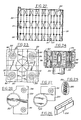
- FIG. 4 the support module 120 is illustrated broken away to enable the showing on a single sheet.
- a partial section of this module is shown in FIG. 13 wherein a top panel is spaced from a bottom panel 142 and the spac, between these panels being filled by a plastic or paper honeycomD material 144, the axis of the honeycomb openings being perpendicular to the panels.
- the panel surfaces may be covered with carpet 141 on one side and vinyl 143 on the other side so that either may be used as the exposed top surface.
- a reinforcement stack 146 which can be formed of pieces of plywood glued together and recessed into the filler material at each corner. Similar reinforcing stacks can be provided along the edges of the module as shown at 148 in FIG. 4.
- the edges of the module are closed by an extruded elongate strip 150 (FIG. 17) which has two parallel flanges 152 extending from one side of the strip. These flanges are preferably provided with saw-tooth ridges 154 as illustrated in FIG. 13 and extending the length of the edge piece 150.
- This edge piece is forced on to the modules by hydraulic or other presses so that the flanges 152 are firmly engaged with the upper and lower panels 140 and 142.
- the edge pieces each have on the outer surface a re-entrant slot 156 with vertically spaced upper and lower flanges 158. The purpose of this groove will be later described.
- sockets 160 (See FIG. 16) preferably formed of metal such as aluminum and also having saw-tooth annular ridges 162 on the outer surface so that when forced into a bole in the blocks 146, they will be securely retained.
- the entrance end of the socket is tapered to facilitate the assembly and the outer end of the socket has a tapered flange 164.
- a plastic plug 166 is shown closing the top of the r socket.
- Each socket also has an internal annular groove 168 which will receive a detent on parts to be assembled thir in These sockets preferably enter the corner from the top and bottom of the support module panel and are coaxial, the inner ends abutting.
- the support module 120 is shown supported by leg elements 170 which are connected by a cross- brace 172.
- a side view of the assembly is shown in FIG. 5 and an end view is shown in FIG. 6.
- the legs have an extensible telescoping section 174 which can be adjustably positioned within the legs and as shown in FIG. 8, the legs 170, four in number, are connected by the horizontal strut 172 and by shorter struts 176.
- the shorter struts can be folded to the longer section as shown in FIG. 8 for shipping purposes.
- FIG. 9 A modified leg structure is shown in FIG. 9 in which the shorter horizontal struts are connected by a diagonal structure-178.
- This frame work can also be collapsed as shown by the arrows.
- the horizontal end struts are pivoted on suitable sleeves 180 surrounding the legs in such a way that the frame work can be collapsed as described.
- Each telescoped leg portion 174 has an adjustable foot 182 to contact a supporting surface.
- FIG. 15 the means for locking the telescoping portions 174 to the leg portion 170 is shown in the form of a headed bolt 184 which has a pivoted retainer latch 186.
- the top of the leg-portions 170 is illustrated in FIG. 10 and in FIG. 11.
- a flange 188 is positioned at the top of the leg and a conical projection 190 extends upwardly from the flange having a spring- backed ball detent 192 which will cooperate with the annular recesses 168 of the sockets 160.
- a threaded recess 194 at the top end of the conical portion allows a securing bolt to be received when dictated by the particular use.
- FIG. 18 a perspective view of a corner of a support module 120 is illustrated, the extruded edge strips 150 being also illustrated.
- a short angle piece 196 is illustrated which may be utilized for further vertical closure of the corners of the unit. This angle piece 196 is shown in FIGS. 5, 6, 7 and 18.
- the inner side of the edge pieces 150, and particularly the re-entrant groove shape, is recessed to receive a side or wing of the angle 196 and this angle is pop-riveted to the ends of the conjunctive edge pieces at the corners so the edge pieces are mechanically locked together at the corners of the panel module.
- the socket 160 is closed by the plastic plug 166.
- the re-entrant groove 156 has a notched portion 198 to admit the entrance of a vertical support element 200.
- This element has a bottom edge which will be received in the lower portion of the re-entrant groove and a bifurcate top edge 202, the inner portion of which is received in the upper portion of the re-entrant groove and the outer portion is spaced outwardly.
- the edges may be secured to each other by the elements 200, as shown best in FIG. 21.
- the re-entrant grooves 156 in each case are facing each other and the element 200 is secured in one of the re-entrant grooves and the outer portion of the bifurcate upper edge is hooked into the re-entrant groove of an adjacent edge strip.
- the panels are locked together horizontally and furnish multiple vertical support for each other. Suitable leg supports can be utilized as previously described
- FIG. 22 a larger staging assembly is shown composed of a multiplicity in each direction of the support modules 120.
- the corners of the various modules are interlocked by a leg plate which has four upstanding projections to be received in the sockets 160 on the bottom of the corners of the modules.
- a different leg is utilized as shown best in FIGS. 29 to 33. Where four corners are to be joined, each leg has a square panel 210.
- the leg tube 212 has the top portion welded to a square panel 210 with conical inserts 190 described in connection with FIGS. 10 and 11 but having a shorter vertical dimension to facilitate the assembly.
- the top socket 160 has an insert 214 through which a headed bolt 216 is passed to thread into the threaded recess of the part 190.
- FIG. 23 the four corners of modules 120 meet at point 220 and the bolts 216 are illustrated. Thus, the four corners are mechanically secured together.
- the circle 23 in FIG. 22 encircles one of the four corner assemblies which is enlarged in FIG. 23. It will be understood that in the assembly shown in FIG. 22, only every other panel needs to have a leg section, the intervening panels being supported by the adjacent panels. In each case, it is preferable that there be an odd number of modules in each direction to accomplish this. However, if an even number is a requirement, adapter legs can be provided.
- a special unit can be usod as shown in FIG. 27, where the leg 212 has a quartered plate 222 with a single projection 190.
- the leg tube 212 can have a half plate 224 with two upward projections 190.
- a block 230 shown in FIG. 26, is inserted in one of the re-entrant grooves of an edge plate and projects into an adjacent re-entrant groove as illustrate in FIG. 25.
- the shorter cones 190 allow the blocks 230 to be inserted between adjacent panels and the panels to be located on the cones in the assembly.
- the leg frames for a structure illustrated in FIG. 22 are shown best in FIG. 29 where cross-bars are provided to reinforce the structure.
- cross-bars can have drop-in sections, as illustrated in FIG. 31, where a recess 232 can receive a downwardly projecting portion of a cross-bar, for example, in FIG. 31, the horizontal cross-bars 234.
- Diagonal cross-bars 236 may also be utilized for horizontal stability.
- FIG. 34 there is illustrated a staging unit utilized for choral groups wherein a series of risers provide horizontal support for people standing in line, each line being at a different level than the next.
- a main back section 250 two wing portions 252, and angled connector portion 254.
- An end view, in small dimension, is illustrated in FIG. 35 with railings 256.
- a larger view is shown in FIG. 36 wherein a series of support modules 120 are mounted at different levels in overlapping relationship to provide a choral riser. The same support panels are used in this combination as in the previously described embodiments.
- next adjacent rising panels each have a long leg support for the rear portion and a short leg support for the front portion which will rest on the next adjacent lower panel.
- Railing stanchions 258 can insert into the sockets 160 in the outer corners of the various risers.
- cable reinforcing devices utilizing cables 260 can be anchored at various portions to stabilize the unit horizontally.
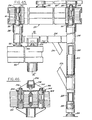
- a device is provided to tighten the cables which are anchored at the top. The tightening device is shown in FIGS. 42 and 43 which are enlargements of the encircled portion 42 of FIGS. 37 and 41.
- a circular cam 272 is rotatably mounted and carries an eccentric pivot pin 274 to which the cables are connected. Rotation of the cam as shown in FIG. 43 will tighten the cables 260 to provide the proper tension.
- drop-in horizontal bars referenced generally at 280, have downwardly projecting portions 281 which socket in side mounted tubes 282. See also FIG. 38.
- a U-shaped spring clip 284 with a button 286 is utilized to lock the horizontal bars in place until intentionally released.
- FIG. 40 shows a section on line 40--40 of FIG. 38.
- FIG. 45 a section taken on line 45--45 of FIG. 36.
- the support module 120 has a depending leg 288 with a foot pad 182 resting on the lower module 120.
- the leg 288 has the conical projection 190 which projects into the socket 160 and is retained by the insert 214 and bolt 216.
- the longer leg 290 extends down to the supporting surface and also has a projection 190 secured in the support module 12C by A lateral bar 294 connects the legs and is diagonally supported by a strut 296.
- FIG. 45 shows the bar 294 mounted in a yoke 298 supported in a gusset 300 on a plate 302. This plate is secured by plugs 304 and bolts 306 to the support module 120.
- the yoke 298 is designed to be located at various points along the bar 294. See, for example, the threaded recess 307.
- the overlap of the risers can be adjusted as desired and still locked in place.
- the risers are secured to each other through the respective corner sockets and supported by the horizontal lateral members as well as by the tightened cables.
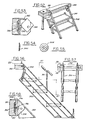
- FIGS. 47, 48 and 49 there are showings of the manner in which a railing can be secured to the risers at the outer edges.
- a railing stanchion 310 is suitably supported in a socket 160 through a conical insert 312 (See FIGS. 47 and 50.).
- the stanchion 310 has a plate 314 which rests on a support module 120.
- a bayonet slot 316 shown in FIGS. 47 and 50, is utilized in conjunction with a cross-pin 318 on a threaded shaft 317 which is resiliently biased upwardly by a coil spring 319. This pin will move the threaded shaft 317 vertically to retract it into the cone 312 for protection during shipping.
- the railings are pivotally mounted on a top piece 320 at the joints 322 and 324 (FIG. 49) so that the railings can be aligned as in FIG. 47 or angled as in FIG. 48.
- the structure shown in FIG. 51 is utilized where the side beam of the stair rail 330 has a socket member 332 welded thereto to receive the lower end of a rail stanchion 310.
- a small two-step stair unit 340 is connected to the side rail 150 by a mechanism shown in the sectional view in FIG. 53 taken on line 53--53 of FIG. 52.
- the rail of the stair 340 is mounted on a bracket 342 which has fastened thereto a multi-diameter disc 344 as shown in FIGS. 54 and 55.
- a nut and bolt combination 346 holds the disc on the outer face of the bracket 342. This disc will slip into the re-entrant groove of the elongate extruded edge 150 of the modules and thus secure the stairs vertically so that the treads 348 can be utilized.
- FIGS. 56 and 57 a longer stair unit is shown having side angle rails 350 and 354 suitably connected together.
- the top of the rail 350 is connected to the edge of a support module by a mechanism illustrated in section in FIG. 58.
- a gusset bracket 354 has a flange 356 with a turned portion 358 which overlies the metallic edge of the support module.
- This unit also utilizes the discs 344 described in connection with FIGS. 53 to 55, which discs slide in the re-entrant grooves of the module edge 150.
- FIGS. 59 to 61 there is illustrated a means of mounting curtains on the support modules 120.
- Plastic slide elements 360 can be mounted in the re-entrant grooves of the side members 150 having a Velcro surface on the outside.
- a curtain 362 having a Velcro strip 364 can be mounted at intervals along the side of a support module. It is also possible to shorten the curtain by folding it under and utilizing Velcro inserts 366 to fasten the curtain to a shorte vertion a height as shown in FIG. 61.
- the same Velcro strip 360 can be utilized for this purpose.
- FIG. 63 simply shows a curtain 370 on a supported rod 372.
- FIGS. 64 to 67 an accessory for handling the support modules 120 is illustrated.
- This comprises a unit 380 shown in plan view in FIG. 65.
- This unit has two rollers 382 at each end and has on the top surface a flanged support plate 384 supported on a bolt 386 which is biased toward the unit by a spring 388.
- the sides of the support plate 384 will insert into the re-entrant groove of the extruded edges of the module as shown in FIG. 67.
- these accessories 380 can be readily applied to the side edge of a module and the module easily rolled along a supporting surface to a place where it is to be mounted.
- the units 380 can then be stripped off of the edge and re-used for other units.
Landscapes
- Engineering & Computer Science (AREA)
- Architecture (AREA)
- Civil Engineering (AREA)
- Structural Engineering (AREA)
- Multimedia (AREA)
- Forms Removed On Construction Sites Or Auxiliary Members Thereof (AREA)
- Steps, Ramps, And Handrails (AREA)
- Package Frames And Binding Bands (AREA)
- Floor Finish (AREA)
- Pressure Welding/Diffusion-Bonding (AREA)
- Bridges Or Land Bridges (AREA)
Applications Claiming Priority (2)
| Application Number | Priority Date | Filing Date | Title |
|---|---|---|---|
| US06/607,978 US4638604A (en) | 1984-05-07 | 1984-05-07 | Staging structure |
| US607978 | 1984-05-07 |
Publications (3)
| Publication Number | Publication Date |
|---|---|
| EP0160843A2 true EP0160843A2 (fr) | 1985-11-13 |
| EP0160843A3 EP0160843A3 (en) | 1986-12-03 |
| EP0160843B1 EP0160843B1 (fr) | 1991-09-11 |
Family
ID=24434511
Family Applications (1)
| Application Number | Title | Priority Date | Filing Date |
|---|---|---|---|
| EP85104084A Expired EP0160843B1 (fr) | 1984-05-07 | 1985-04-03 | Structure d'estrade |
Country Status (6)
| Country | Link |
|---|---|
| US (1) | US4638604A (fr) |
| EP (1) | EP0160843B1 (fr) |
| JP (1) | JPH0637812B2 (fr) |
| CA (2) | CA1257064A (fr) |
| DE (1) | DE3584033D1 (fr) |
| ES (1) | ES8605313A1 (fr) |
Cited By (7)
| Publication number | Priority date | Publication date | Assignee | Title |
|---|---|---|---|---|
| EP0264356A1 (fr) * | 1986-10-14 | 1988-04-20 | Carl-Eric Sandgren | Podium pour scène |
| GB2220851A (en) * | 1988-07-04 | 1990-01-24 | Kenrich Group Holdings Plc | Platform apparatus |
| FR2668194A1 (fr) * | 1990-10-22 | 1992-04-24 | Cre Rossi | Ensemble d'elements assemblables pour la construction, indifferemment, de gradins ou de podiums. |
| WO2012167899A3 (fr) * | 2011-06-10 | 2013-04-11 | Overesch Hubert | Podium transportable |
| US8869713B2 (en) | 2008-06-09 | 2014-10-28 | Michael Tait | Portable locking support and platform system |
| US9259639B2 (en) | 2012-06-01 | 2016-02-16 | Tait Towers Manufacturing, LLC | Self-leveling platform system, self-leveling supports, and method of assembling a self-leveling platform system |
| GB2605968A (en) * | 2021-04-19 | 2022-10-26 | J Mac Safety Systems Ltd | A corner mounting bracket for a work platform |
Families Citing this family (46)
| Publication number | Priority date | Publication date | Assignee | Title |
|---|---|---|---|---|
| US4783934A (en) * | 1986-11-21 | 1988-11-15 | United Production Services, Inc. | Free-standing assembly and method for making same |
| US4759162A (en) * | 1987-04-16 | 1988-07-26 | Wyse Steven J | Modular platform assembly |
| DE3810818A1 (de) * | 1988-03-30 | 1989-10-12 | Wund Josef Dipl Ing Fh | Einrichtung zur unterschiedlichen nutzbarkeit einer mit einem rasenbelag oder einem aehnlichen belag versehenen flaeche |
| US4845915A (en) * | 1988-06-27 | 1989-07-11 | Stageright Corporation | High impact panel corner |
| US4843792A (en) * | 1988-06-27 | 1989-07-04 | Stageright Corporation | Socket support and interlock for staging panels |
| US4863126A (en) * | 1988-08-01 | 1989-09-05 | Stageright Corporation | Theater curtain frame assembly and storage assembly |
| US4917217A (en) * | 1989-01-23 | 1990-04-17 | Stageright Corporation | Portable folding staging |
| US5325640A (en) * | 1991-08-09 | 1994-07-05 | Sico Incorporated | Folding stage system |
| CA2101577C (fr) * | 1992-07-31 | 2005-06-07 | Dale L. Taipale | Scene modulaire portable |
| US5317842A (en) * | 1992-07-31 | 1994-06-07 | Stageright Corporation | Fold and roll retractable locator |
| US5323563A (en) * | 1992-07-31 | 1994-06-28 | Stageright Corporation | Retractable locators for deck panels of portable staging |
| US5323564A (en) * | 1992-10-02 | 1994-06-28 | Showtech, Inc. | Performance stage deck and assembly method |
| US5660121A (en) * | 1995-02-24 | 1997-08-26 | Sico Incorporated | Folding framework and support legs |
| US6024026A (en) * | 1997-06-20 | 2000-02-15 | Sico Incorporated | Tri-height folding stage |
| US6070367A (en) * | 1997-08-01 | 2000-06-06 | Sico Incorporated | Folding stage |
| US6164017A (en) * | 1999-01-06 | 2000-12-26 | Sico Incorporated | Adjustable linkage |
| GB0011760D0 (en) * | 2000-05-17 | 2000-07-05 | Larner Paul | Stage deck |
| US6729075B2 (en) * | 2000-10-19 | 2004-05-04 | Wenger Corporation | Audience seating system |
| USD459003S1 (en) | 2000-12-15 | 2002-06-18 | Rogers Athletic Company | Telescopic seating riser |
| US7007428B2 (en) * | 2001-01-18 | 2006-03-07 | Santa Cruz Cathy D | Vertical telescopic stage accessories device |
| CA2331800A1 (fr) * | 2001-01-22 | 2002-07-22 | Moritz F. Gruber | Systeme de plancher graphique portatif |
| US6581339B2 (en) | 2001-02-13 | 2003-06-24 | Wenger Corporation | Erectable platform |
| US6520460B2 (en) | 2001-07-16 | 2003-02-18 | Stageright Corporation | Extendible leg device |
| US6598351B2 (en) | 2001-07-16 | 2003-07-29 | Stageright Corporation | Telescopic seating riser assembly |
| US20050034378A1 (en) * | 2002-06-06 | 2005-02-17 | Underwood Robert A. | Partition system |
| US7874115B2 (en) * | 2003-02-07 | 2011-01-25 | Wenger Corporation | Modular floor |
| AU2004202341B2 (en) * | 2004-05-27 | 2010-03-04 | Ideal Plastic Concepts (Aust.) Pty Ltd | Modular Platform Assembly & System |
| US20060131251A1 (en) * | 2004-12-21 | 2006-06-22 | Stadler Theodore A | Performance riser assembly |
| US20060265987A1 (en) * | 2005-05-27 | 2006-11-30 | Iannone Edward J | Portable deck |
| US7703401B2 (en) * | 2005-12-07 | 2010-04-27 | Tait Towers | Portable locking support structure |
| US8991105B2 (en) * | 2006-03-10 | 2015-03-31 | Donald L. Harvey | Collapsible building having rigid walls |
| US7900402B2 (en) * | 2006-10-04 | 2011-03-08 | Stageright Corporation | Powered dual level telescopic seating riser assembly |
| US7716895B2 (en) * | 2006-10-26 | 2010-05-18 | Tait Towers, Inc. | Portable light emitting stage |
| SE531036C2 (sv) * | 2007-04-02 | 2008-11-25 | Bae Systems Haegglunds Ab | Hjulupphängning för hjulfordon |
| US20090252550A1 (en) * | 2008-04-07 | 2009-10-08 | Smith Richard D | Portable Elevated Platform with Locking Legs |
| US20090250295A1 (en) * | 2008-04-07 | 2009-10-08 | Laws David J | Portable Elevated Platform |
| US20090300994A1 (en) * | 2008-06-06 | 2009-12-10 | Atkins Iii Livingston Elwood | Removable stairway for an elevated platform and method |
| DE102008029872B4 (de) * | 2008-06-24 | 2010-06-24 | George Minko | Mobiles Gebäude |
| US8272338B2 (en) * | 2009-09-28 | 2012-09-25 | Leslie Ho Leung Chow | Safe anchoring device |
| JP6059418B2 (ja) * | 2010-10-01 | 2017-01-11 | 積水化学工業株式会社 | 外壁パネルの取付構造およびそれを用いたユニット建物の製造方法 |
| US8474190B1 (en) * | 2011-07-21 | 2013-07-02 | Derek J. Sanderson | Portable modular seating assembly |
| JP6000894B2 (ja) * | 2013-04-01 | 2016-10-05 | オムロンオートモーティブエレクトロニクス株式会社 | 車両用携帯機 |
| KR20140131090A (ko) * | 2013-05-03 | 2014-11-12 | 한국전자통신연구원 | 과수용 반사판 관리 장치 및 이를 이용한 방법 |
| US11002023B2 (en) * | 2013-06-14 | 2021-05-11 | Phillip Busby | Flooring support system |
| US20220186507A1 (en) * | 2020-11-30 | 2022-06-16 | Grady F. Smith | Multi-Function Scaffold with Reversible Platform |
| US20240266987A1 (en) * | 2024-03-08 | 2024-08-08 | Wencon Development, Inc., Dba Quick Mount Pv | Waterproofing Mounting System for Attaching Solar Modules to a Roof |
Family Cites Families (35)
| Publication number | Priority date | Publication date | Assignee | Title |
|---|---|---|---|---|
| DE518889C (de) * | 1931-02-21 | Hans Wolff Dipl Ing | Treppenfoermiges Waren-Schaugestell | |
| US2380692A (en) * | 1942-06-22 | 1945-07-31 | Durnison Homes Inc | Adjustable building foundation |
| US2602012A (en) * | 1949-11-03 | 1952-07-01 | George E Doty | Rotatable leg construction for reversible table tops |
| US2944780A (en) * | 1958-05-27 | 1960-07-12 | Monk Sterling Norris | Furniture joint |
| US3011586A (en) * | 1958-10-07 | 1961-12-05 | Jr John E Harvey | Fold-up tower section |
| US3217366A (en) * | 1959-11-18 | 1965-11-16 | Harry J Wenger | Sound projecting shell |
| US3181203A (en) * | 1961-02-15 | 1965-05-04 | Harry J Wenger | Portable stage and shell |
| US3235926A (en) * | 1963-07-19 | 1966-02-22 | Velcro Corp | Drapery hardware |
| US3416282A (en) * | 1966-06-16 | 1968-12-17 | Cardinal Extrusions Co | Elongate panel edging strip of the prefabricated type |
| US3489085A (en) * | 1967-08-11 | 1970-01-13 | David M Co | Printing blanket edging and anchoring means |
| US3504766A (en) * | 1968-03-13 | 1970-04-07 | Joseph Emmett Boyd | Ladders |
| US3503166A (en) * | 1968-03-22 | 1970-03-31 | Yosh Nakazawa & Associates Inc | Architectural system of interior modular construction |
| US3572224A (en) * | 1968-10-14 | 1971-03-23 | Kaiser Aluminium Chem Corp | Load supporting plank system |
| US3606704A (en) * | 1969-05-02 | 1971-09-21 | Resilient Services Inc | Elevated floor structure |
| GB1340185A (en) * | 1970-03-16 | 1973-12-12 | Ari Propaflor Ltd | Flooring |
| US3608937A (en) * | 1970-05-04 | 1971-09-28 | Bendix Corp | Coupling device |
| US3813179A (en) * | 1970-06-01 | 1974-05-28 | Alum Elec Structures Inc | Structures formed from structural members |
| US3632154A (en) * | 1970-06-29 | 1972-01-04 | Paul F Woodrich | Heat-retaining partition for automotive van |
| US3747706A (en) * | 1971-11-18 | 1973-07-24 | Wenger Corp | Portable folding riser |
| US3968606A (en) * | 1972-12-04 | 1976-07-13 | Facemire Odie D | Portable rostrum |
| NL7400382A (fr) * | 1973-02-01 | 1974-08-05 | ||
| US3788608A (en) * | 1973-03-06 | 1974-01-29 | American Seating Co | Modular folding rail |
| DE2549491A1 (de) * | 1975-11-05 | 1977-05-12 | Hammann Theaterwerkstaetten | Baukastensystem zur erstellung von buehnenaufbauelementen |
| DE7616250U1 (de) * | 1976-05-21 | 1976-09-23 | Eisenberg, Hans-Jochen, 5600 Wuppertal | Hoehenverstellbarer podestbock zum aufbau von buehnenpodesten o.dgl. |
| US4103463A (en) * | 1976-09-28 | 1978-08-01 | Panelfold Doors, Inc. | Portable wall system |
| DE2846341A1 (de) * | 1978-10-25 | 1980-05-08 | Aluminium Press Walzwerk | Kot- und faekaliendurchlaessiger stallboden |
| DD141702A1 (de) * | 1979-03-05 | 1980-05-14 | Heinz Krause | Verbindungsbeschlag zum verbinden von moebelteilen |
| US4308963A (en) * | 1979-12-17 | 1982-01-05 | Worrallo A C | Shelves |
| US4409762A (en) * | 1981-02-23 | 1983-10-18 | American Seating Company | Row structure for telescoping seating systems and method of assembling same |
| FR2501267A1 (fr) * | 1981-03-03 | 1982-09-10 | Entrepose | Plancher d'echafaudage |
| DE3114590A1 (de) * | 1981-04-10 | 1982-10-28 | Hans Jochen Eisenberg | Bausatz zum aufbau von podesten, buehnenboeden, tanzboeden o.dgl. |
| US4403366A (en) * | 1981-09-15 | 1983-09-13 | Lucke Harold J | Towel and mounting method and means |
| US4431082A (en) * | 1981-12-30 | 1984-02-14 | Bott John Anthony | Vehicle ladder |
| DE8221523U1 (de) * | 1982-07-29 | 1982-11-18 | Gebr. Mott GmbH Metallwarenfabrik und Bühnenbau, 6972 Tauberbischofsheim | Transportable tanzflaeche |
| US4462485A (en) * | 1983-01-17 | 1984-07-31 | Step-On Inc. | Ladders for transoms of boats |
-
1984
- 1984-05-07 US US06/607,978 patent/US4638604A/en not_active Expired - Fee Related
-
1985
- 1985-04-02 CA CA000478185A patent/CA1257064A/fr not_active Expired
- 1985-04-03 EP EP85104084A patent/EP0160843B1/fr not_active Expired
- 1985-04-03 DE DE8585104084T patent/DE3584033D1/de not_active Expired - Lifetime
- 1985-04-24 JP JP60086620A patent/JPH0637812B2/ja not_active Expired - Lifetime
- 1985-05-06 ES ES542841A patent/ES8605313A1/es not_active Expired
-
1988
- 1988-06-27 CA CA000570550A patent/CA1278164C/fr not_active Expired - Fee Related
Cited By (9)
| Publication number | Priority date | Publication date | Assignee | Title |
|---|---|---|---|---|
| EP0264356A1 (fr) * | 1986-10-14 | 1988-04-20 | Carl-Eric Sandgren | Podium pour scène |
| GB2220851A (en) * | 1988-07-04 | 1990-01-24 | Kenrich Group Holdings Plc | Platform apparatus |
| GB2220851B (en) * | 1988-07-04 | 1992-03-25 | Kenrich Group Holdings Plc | Platform apparatus |
| FR2668194A1 (fr) * | 1990-10-22 | 1992-04-24 | Cre Rossi | Ensemble d'elements assemblables pour la construction, indifferemment, de gradins ou de podiums. |
| US8869713B2 (en) | 2008-06-09 | 2014-10-28 | Michael Tait | Portable locking support and platform system |
| WO2012167899A3 (fr) * | 2011-06-10 | 2013-04-11 | Overesch Hubert | Podium transportable |
| US9259639B2 (en) | 2012-06-01 | 2016-02-16 | Tait Towers Manufacturing, LLC | Self-leveling platform system, self-leveling supports, and method of assembling a self-leveling platform system |
| GB2605968A (en) * | 2021-04-19 | 2022-10-26 | J Mac Safety Systems Ltd | A corner mounting bracket for a work platform |
| GB2605968B (en) * | 2021-04-19 | 2025-04-02 | J Mac Safety Systems Ltd | A corner mounting bracket for a work platform |
Also Published As
| Publication number | Publication date |
|---|---|
| CA1278164C (fr) | 1990-12-27 |
| US4638604A (en) | 1987-01-27 |
| JPS60238577A (ja) | 1985-11-27 |
| ES8605313A1 (es) | 1986-04-01 |
| JPH0637812B2 (ja) | 1994-05-18 |
| CA1257064A (fr) | 1989-07-11 |
| EP0160843A3 (en) | 1986-12-03 |
| EP0160843B1 (fr) | 1991-09-11 |
| DE3584033D1 (de) | 1991-10-17 |
| ES542841A0 (es) | 1986-04-01 |
Similar Documents
| Publication | Publication Date | Title |
|---|---|---|
| EP0160843A2 (fr) | Structure d'estrade | |
| EP2432962B1 (fr) | Système d'escaliers réemployable | |
| US4104835A (en) | Portable staging equipment | |
| US5156235A (en) | Set-up bracket for scaffolding | |
| EP0464330B1 (fr) | Support pliable pour scènes ou gradins à plusieurs niveaux | |
| US9631371B2 (en) | Modular and collapsible ramp system | |
| US3808757A (en) | Dismantleable porch installation | |
| US6922947B2 (en) | Audience seating system | |
| AU2018201353B2 (en) | Improved Modular and Collapsible Ramp System | |
| US7353639B2 (en) | Recreational vehicle portable deck | |
| US5740575A (en) | Ramp systems | |
| US8733838B2 (en) | Floor track for seating system | |
| US4296573A (en) | Audience control barrier | |
| US9689171B1 (en) | Staging transport assembly and method | |
| US2241281A (en) | Portable bleacher | |
| US20020056239A1 (en) | Removable safety end rail for bleachers | |
| US20080163991A1 (en) | Portable Screen System | |
| US5996286A (en) | Mobile collapsible seating and presentation unit | |
| JPH0722450Y2 (ja) | 簡易舞台 | |
| GB2271584A (en) | A barrier for crowd control |
Legal Events
| Date | Code | Title | Description |
|---|---|---|---|
| PUAI | Public reference made under article 153(3) epc to a published international application that has entered the european phase |
Free format text: ORIGINAL CODE: 0009012 |
|
| AK | Designated contracting states |
Designated state(s): DE FR GB IT SE |
|
| PUAL | Search report despatched |
Free format text: ORIGINAL CODE: 0009013 |
|
| AK | Designated contracting states |
Kind code of ref document: A3 Designated state(s): DE FR GB IT SE |
|
| 17P | Request for examination filed |
Effective date: 19870429 |
|
| RAP3 | Party data changed (applicant data changed or rights of an application transferred) |
Owner name: STAGERIGHT CORPORATION |
|
| 17Q | First examination report despatched |
Effective date: 19890717 |
|
| GRAA | (expected) grant |
Free format text: ORIGINAL CODE: 0009210 |
|
| ITF | It: translation for a ep patent filed | ||
| AK | Designated contracting states |
Kind code of ref document: B1 Designated state(s): DE FR GB IT SE |
|
| ET | Fr: translation filed | ||
| REF | Corresponds to: |
Ref document number: 3584033 Country of ref document: DE Date of ref document: 19911017 |
|
| PGFP | Annual fee paid to national office [announced via postgrant information from national office to epo] |
Ref country code: FR Payment date: 19920312 Year of fee payment: 8 |
|
| PGFP | Annual fee paid to national office [announced via postgrant information from national office to epo] |
Ref country code: DE Payment date: 19920313 Year of fee payment: 8 |
|
| PGFP | Annual fee paid to national office [announced via postgrant information from national office to epo] |
Ref country code: SE Payment date: 19920316 Year of fee payment: 8 |
|
| PGFP | Annual fee paid to national office [announced via postgrant information from national office to epo] |
Ref country code: GB Payment date: 19920326 Year of fee payment: 8 |
|
| PLBE | No opposition filed within time limit |
Free format text: ORIGINAL CODE: 0009261 |
|
| STAA | Information on the status of an ep patent application or granted ep patent |
Free format text: STATUS: NO OPPOSITION FILED WITHIN TIME LIMIT |
|
| 26N | No opposition filed | ||
| PG25 | Lapsed in a contracting state [announced via postgrant information from national office to epo] |
Ref country code: GB Effective date: 19930403 |
|
| PG25 | Lapsed in a contracting state [announced via postgrant information from national office to epo] |
Ref country code: SE Effective date: 19930404 |
|
| GBPC | Gb: european patent ceased through non-payment of renewal fee |
Effective date: 19930403 |
|
| PG25 | Lapsed in a contracting state [announced via postgrant information from national office to epo] |
Ref country code: FR Effective date: 19931229 |
|
| PG25 | Lapsed in a contracting state [announced via postgrant information from national office to epo] |
Ref country code: DE Effective date: 19940101 |
|
| REG | Reference to a national code |
Ref country code: FR Ref legal event code: ST |
|
| EUG | Se: european patent has lapsed |
Ref document number: 85104084.0 Effective date: 19931110 |