EP0160860A2 - Dispositif pour imprimer - Google Patents
Dispositif pour imprimer Download PDFInfo
- Publication number
- EP0160860A2 EP0160860A2 EP85104525A EP85104525A EP0160860A2 EP 0160860 A2 EP0160860 A2 EP 0160860A2 EP 85104525 A EP85104525 A EP 85104525A EP 85104525 A EP85104525 A EP 85104525A EP 0160860 A2 EP0160860 A2 EP 0160860A2
- Authority
- EP
- European Patent Office
- Prior art keywords
- printing
- data
- memory
- line
- period
- Prior art date
- Legal status (The legal status is an assumption and is not a legal conclusion. Google has not performed a legal analysis and makes no representation as to the accuracy of the status listed.)
- Granted
Links
Images




Classifications
-
- G—PHYSICS
- G01—MEASURING; TESTING
- G01G—WEIGHING
- G01G19/00—Weighing apparatus or methods adapted for special purposes not provided for in the preceding groups
- G01G19/40—Weighing apparatus or methods adapted for special purposes not provided for in the preceding groups with provisions for indicating, recording, or computing price or other quantities dependent on the weight
- G01G19/413—Weighing apparatus or methods adapted for special purposes not provided for in the preceding groups with provisions for indicating, recording, or computing price or other quantities dependent on the weight using electromechanical or electronic computing means
- G01G19/414—Weighing apparatus or methods adapted for special purposes not provided for in the preceding groups with provisions for indicating, recording, or computing price or other quantities dependent on the weight using electromechanical or electronic computing means using electronic computing means only
- G01G19/415—Weighing apparatus or methods adapted for special purposes not provided for in the preceding groups with provisions for indicating, recording, or computing price or other quantities dependent on the weight using electromechanical or electronic computing means using electronic computing means only combined with recording means
-
- G—PHYSICS
- G01—MEASURING; TESTING
- G01G—WEIGHING
- G01G23/00—Auxiliary devices for weighing apparatus
- G01G23/18—Indicating devices, e.g. for remote indication; Recording devices; Scales, e.g. graduated
- G01G23/38—Recording and/or coding devices specially adapted for weighing apparatus
- G01G23/42—Recording and/or coding devices specially adapted for weighing apparatus electrically operated
-
- G—PHYSICS
- G06—COMPUTING OR CALCULATING; COUNTING
- G06K—GRAPHICAL DATA READING; PRESENTATION OF DATA; RECORD CARRIERS; HANDLING RECORD CARRIERS
- G06K1/00—Methods or arrangements for marking the record carrier in digital fashion
- G06K1/12—Methods or arrangements for marking the record carrier in digital fashion otherwise than by punching
- G06K1/126—Methods or arrangements for marking the record carrier in digital fashion otherwise than by punching by photographic or thermographic registration
Definitions
- the present invention relates to a printing apparatus which prints data including weighing data on a label with a thermal head.
- a printing apparatus having two or more thermal heads provided for respective printing color has been proposed.
- Such a printing apparatus has a complex structure.
- a printing apparatus comprising a thermal head having N heating elements arranged in a line and selectively energized in correspondence to N-bit data; first and second memories for respectively storing first and second printing infomation, the first and second printing information respectively having a plurality of line printing information to be printed on a label by means of the N heating elements; and a control unit which reads out one line printing information from each of the first and second memories, supplies, during a first printing period of each printing cycle, the N-bit data to the thermal head in accordance with a logical sum of the one line printing information read out from the first memory and the one line printing information read out from the second memory and supplies, during a second printing period of each printing cycle, the N-bit data to the thermal head in accordance with the one line printing information read out from the first memory.
- first printing information which is determined as special data is stored in the first memory which is separate from second printing information stored in the second memory. Therefore, printing operations for both the first and second printing information can be easily performed, and that only for the first printing information can also be easily performed. Therefore, printing periods corresponding to printing operations for the first and second printing information can be independently set. Thus, dots printed on a single line can be easily printed with different colors or densities.
- Fig. 1 is a label convey mechanism for conveying labels 1 attached to backing paper 2 at an equal pitch and used in a printing apparatus according to an embodiment of the present invention.
- the backing paper 2 is wound around a label supply roller.
- the backing paper 2 is fed to a lable peeling plate 6 through a platen 5 driven by a motor 4, and is bent downward by a distal end portion of the plate 6. Then, the paper 2 is wound around a take-up roller 9 driven by a motor 8 through a guide roller 7.
- a thermal head 10 is arranged so as to contact the label 1 located on the platen 5.
- a distal end portion of the label 1 peeled from the paper 2 on the plate 6 is optically detected by a detector 11. For example, when the detector 11 detects the distal end portion of the label, it generates an output signal changing from low level to high level. On the other hand, when the presence of the label is being detected, the detector 11 continuously generates a high level output signal.
- Fig. 2 shows an example of contents printed on the label 1.
- fixed information 12 such as "PACKED ON”, “effective date”, "PRICE/100 g (S)", “NET WT (g)”, “TOTAL PRICE ($)", “SELL BY”, “division lines” and the like is previously printed.
- a name of item 13, a date 14, bar code 15, weight, unit price and total price data 16, and special information 17 are printed on the label by the thermal head 10.
- the special information 17 "SPECIAL AD" is to be emphasized in this embodiment and is printed by a means (to be described later) with a different color or density.
- a label comprising an upper layer containing a black color agent and a lower layer containing a red color agent is used. When this label is heated by heating elements for a short period of time, black printing is performed, and when it is heated for a long period of time, red printing is performed.
- Fig. 3 shows an electric circuit of the printing apparatus according to the embodiment of the present invention.
- a printing control 18 is provided which is operated in response to a print command or a label detecting signal.
- Two output ports of a weighing scale 19 are connected to the printing control 18 so as to separately supply the special data 17 and ordinary printing information.
- Two data output ports of the control 18 are respectively connected to a first printing buffer memory 25 for storing the special information 17 and a second printing buffer memory 26 for storing the ordinary printing information.
- the printing buffer memories 25 and 26 are connected to the control 18 through X and Y address lines, respectively.
- the first printing buffer memory 25 is connected to a shift register 28 of the thermal head 10 through an OR gate 27.
- the second printing buffer memory 26 is connected to one input terminal of an AND gate 29 having the other input terminal connected to a color control line of the control 18.
- the output terminal of the AND gate 29 is connected to the OR gate 27.
- Data designated by the X and Y address and read out from the buffer memories 25 and 26 is supplied to a shift register 28 by one bit in response to a clock CLK.
- N-bit data stored in the shift register 28 is temporarily stored in a latch circuit 30 connected in parallel to the shift register 28 in response to a strobe signal STB.
- the output terminals of the latch circuit 30 are respectively connected through N AND gates 31-1 to 31-N to the bases of npn transistors 34-1 to 34-N.
- the collectors of the transistors 34-1 to 31-N are connected to heating elements 33-1 to 33-N each having one end commonly connected to a power source 32 so as to perform control of power supply to these elements 33-1 to 33-N.
- the AND gates 31-1 to 31-N are enabled in response to an enable signal ENB. In this case, the conduction states of the transistors 34-l to 34-N are controlled in accordance with data from the latch circuit 30.
- the control 18 is also connected to a timer 35 serving as an ON time controller.
- the timer 35 starts counting in response to a signal Tl generated at a period Pl from the control 18 and generates an output signal T2 which limits a time P2.
- the time P2 defines a period during which contents of the first and second printing buffer memories are simultaneously printed, as will be described later.
- the timer 35 is connected to a variable resistor 36 so as to allow the time P2 to be adjustable.
- control 18 is connected to a motor driver 34 connected to the motor 4, thus feeding the label 1 by one line for each printing cycle.
- the control 18 supplies a data transfer control signal DTCS which is changed to a high level when the Y address is located at "0" to "N” to one input terminal of an AND gate 37 having the other input terminal which receives the clock signal so as to control supply of the clock signal CLK to the shift register 28.
- the printing control 18 generates the strobe signal STB and the enable signal ENB when either one of the signals Tl and T2 rises.
- the period Pl of the signal Tl is equal to a time required for printing one line of the lable 1
- the motor 4 is driven to feed the label 1 by one line every time the signal Tl is generated.
- one line printing herein means not printing of characters for one line but that of dots for one line.
- the time P2 is limited by the timer 35, and the period Pl is divided into a first printing period corresponding to the time P2 and a second printing period (Pl - P2).
- the output from the timer 35 changes to a high level.
- the X address indicates a row address
- the Y address indicates a column address of each row.
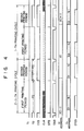
- the control 18 fetches the special information and ordinary printing information from the first and second ouput ports of the weighing scale 19 in response to the print command therefrom and generates X and Y address data designating memory locations so as to store the readout information in the buffer memories 25 and 26. Thereafter, the control 18 periodically generates the signal Tl, and transfers to the shift register 28 the special information and ordinary printing information stored in the buffer memories 25 and 26 in accordance with a timing chart shown in Fig. 5, and further transfers them to the latch circuit 30.
- an i-th printing cycle is executed.
- Each printing cycle is defined by two successive signals Tl.
- the signal Tl is generated in the case of the X address [X(i-1)]
- the output signal T2 from the timer 35 is disabled, a strobe signal STB is generated, and the enable signal ENB is enabled.
- the control 18 sequentially updates the Y addresses from "0" to "N" in sychronism with the clock signals CLK, and thereafter sets it at, e.g., "N+1".
- the special information and ordinary printing information for one line are read out from the buffer memories 25 and 26.
- the N bits in the shift register 28 are latched by the latch circuit 30.
- the N bits in the circuit 30 are supplied to the respective bases of the transistors 34-1 to 34-N through the AND gates 31-1 to 31-N which are enabled by the enable signal ENB, thus controlling conduction states of the transistors 34-1 to 34-N. Therefore, a current is selectively supplied to the heating elements 33-1 to 33-N in accordance with N bits stored in the latch circuit 30.
- the control 18 increments the X address so as to set it at Xl, and sequentially updates the Y address from "0" to "N".
- N bits representing the special information and ordinary printing information for the next one line are read out from the buffer memories 25 and 26.
- the N bits from the buffer memory 25 are supplied to the shift register 28 through the AND gate 29 and OR gate 27 and at the same time the N bits from the buffer memory 26 are also supplied thereto through the OR gate 27. The N.
- bits stored in the shift register 28 are latched by the latch circuit 30 when the next signal Tl is generated after the time Pl has elapsed from the generation of the previous signal Tl, i.e., in response to the strobe signal STB which is generated when the i-th printing cycle is started.
- the heating elements 33-1 to 33-N are selectively energized in accordance with the N bits latched in the latch circuit 30. In other words, N bits corresponding to the logical sum of the N bits representing the special information and the N bits representing the ordinary printing information which are read out from the buffer memories 25 and 26 for one line designated by the X address Xi are printed on one line of the label 1.
- the N bits in the buffer memory 25 designated by the X address Xi are sequentially transferred to the shift register 28 in the same manner as described above.
- the N bits stored in the shift register 28 are latched by the latch circuit 30 when the printing operation of the first printing period ends, i.e., in response to the strobe signal STB generated when the signal T2 rises during the i-th printing cycle.
- the printing operation is performed during the second printing period in accordance with the N bits latched in the latch circuit 30.
- the X address is incremented and is set to be X(i+l).
- the N bits for the line designated by the X address X(i+l) are read out from each of the buffer memories 25 and 26, and N bits corresponding to the readout N-bit data are stored in the shift register 28.
- each printing cycle is divided into the first and second printing periods.
- the N bits corresponding to the logical sum of the N bits in the buffer memory 25 designated by the X address Xi and those in the buffer memory 26 designated by the X address Xi are printed.
- the second printing period only the N bits in the buffer memory 25 designated by the X address Xi are printed. Therefore, the time required for printing the special information in the buffer memory 25 is longer than that required for printing ordinary printing information in the buffer memory 26.
- the special information is printed with a different color or density and can be easily and clearly distinguished from ordinary printing information.
- variable resistor 36 can be properly set so as to set the time P2 in accordance with a heat sensitive property of the label 1.
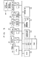
- Fig. 5 shows a block diagram of a printing apparatus according to another embodiment of the present invention.
- the printing apparatus comprises a central processing unit (CPU) 100, a read-only memory (ROM) 102 connected to the CPU 100 through a data bus and storing a control program and the like, and a random-access memory (RAM) 104 for temporarily storing weighing data, character code data and the like.
- the CPU 100 is connected to a character generator 106, a buffer memory 108 for storing special information, and a buffer memory 110 for storing ordinary printing information.
- a weighing scale 112 and a label detector 114 are respectively coupled to the CPU 100 through I/O ports 116 and 118.
- a paper feed motor 120 and a thermal head 122 are coupled to the CPU 100 through a motor driver 124 and a head driver 126, respectively.
- the CPU 100 is coupled to a key-in unit 128 including first and second keyboards and a special information selection key through an I/O port 130.
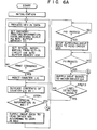
- the CPU 100 After executing the initialization process, the CPU 100 detects the state of the mode key, and after detecting that a key such as pulse number setting key is operated, stores printing information such as a unit price, weight, total price and the like in the buffer memory 110, and then stores the special information, e.g., 'SPECIAL AD.' selected by the special information selection key of the key-in circuit 128 in the buffer memory 108. Thereafter, the CPU 100 checks if the weighing scale 112 has generated a printing command.
- a key such as pulse number setting key is operated
- the CPU 100 If the CPU 100 detects that no printing command is generated, the CPU 100 executes the same operation described above, and stores the printing information from the weighing scale 112 and the special information from the key-in circuit 128 in the buffer memories 110 and 108, respectively. On the other hand, if the CPU 100 detects that the printing command is generated, it sets a line counter LIC in the RAM 104 at "1", and thereafter, reads out the corresponding N-bit data at the respective first lines from the buffer memories 108 and 110 so as to store them in first and second memory areas MAl and MA2 in the RAM 104. In this case, the CPU 100 checks in STEP 1 if bit data constituting a portion of the special information to be printed is included in the N-bit data transferred to the RAM 104 from the buffer memory 108.
- the CPU 100 supplies the N-bit data in the memory area MA2 to the head driver 126 so as to energize the thermal head 122 in accordance with a timing chart shown in Fig. 7.
- the CPU 100 supplies drive data to the head driver 126 so that the thermal head 122 is energized during a predetermined period P10 by the driver 126 in accordance with the N-bit data in the memory area MA2.
- the black dots in accordance with the N-bit data in the memory area MA2 are printed on the label 1.
- the CPU 100 inhibits the head driver 126 from energizing the thermal head 122, and rotates the motor 120 by a given angle so as to feed the label 1 by a given distance.
- the CPU 100 checks if the label detecting signal is generated from the detector 114. If it is YES in STEP 2, the CPU 100 executes the key-in data processing again. If it is NO in STEP 2, the CPU 100 increments the line counter LIC by one, and executes the printing operation in accordance with the N-bit data for the next line.
- the CPU when the CPU detects that the N-bit data in the memory area MA1 include bit data constituting a portion of the special information, it supplies the N-bit data corresponding to a logical sum of the N-bit data in the memory area MA1 and that in the memory area MA2 to the head driver 126 so as to energize the thermal head 122 in accordance with a timing chart shown in Fig. 8.
- the CPU 100 supplies the drive data to the head driver 126 so that it energizes the thermal head 122 in accordance with the N-bit data corresponding to the logical sum of the respective N-bit data in the memory areas MA1 and MA2 for a predetermined period P12 set by the second keyboard of the key-in circuit 128.
- black dots corresponding to the N-bit data of the logical sum are printed on the label 1.
- the CPU 100 inhibits the head driver 126 from energizing the thermal head 122, and sets a numeral "m" set by the first keyboard of the key-in circuit 128 in a pulse number counter PNC in the RAM 104.
- the CPU 100 then supplies the drive data to the head driver 126 so that it energizes the thermal head 122 in accordance with the N-bit data in the memory area MAl for a predetermined period P14.
- those corresponding to the new N-bit data are changed into red dots.
- the CPU 100 sets the head driver 126 in a rest state for the predetermined interval P13, and thereafter, decrements the content of the counter PNC by one. Then, in STEP 3, it is checked if the content of the counter PNC is 0. If it is NO in STEP 3, the CPU 100 sets the head driver 126 in an energized state for the predetermined period P14. If it is YES in STEP 3, the CPU 100 supplies a motor drive signal to the motor driver 124 so as to drive the motor 120 by a given angle, thus feeding the label 1 by a predetermined distance.
- the N-bit data includes the bit data constituting the ordinary printing information and a portion of the special information
- the corresponding heating elements are energized for the period P12
- the corresponding heat elements are energized for a period (Pl3 + m x P14).
- K m 8 is set at "3".
- the ordinary printing information is printed in black
- the special information is printed in red.
- the period P12 which is set by the second keyboard of the key-in circuit 128 must be set to be longer than the period P10. This is because when the N-bit data which does not include the bit data constituting a portion of the special information is sequentially read out from the buffer memory 110, the head driver 126 is alternately set at the energized and rest states, and the ordinary printing information can be effectively printed in black. In this case, since the head driver 126 is repeatedly energized at an interval of the relatively short period Pll, heat remains in the heating elements which were energized in the previous printing cycle when the next printing cycle starts.
- the time ⁇ (m+1) x P13 + m x P141 elapses and then the heating elements which were energized for printing the ordinary printing information in black are energized in the next printing cycle, and a temperature of the heating elements is sufficiently lowered. Therefore, in this case, in order to effectively perform black printing, it is important to set the period P12 to be long. Note that the period Pll can be set to be the same as the period P13.
- the ordinary printing information is printed during the first to fourth printing cycles, i.e., black printing is executed, and during the fifth to seventh printing cycles, the ordinary printing information and the special information are printed, i.e., black and red printing operations are simultaneously performed.
- an interval of each printing cycle is set to be short.
- the heating elements are energized to print, e.g., bar codes during the continuous printing cycles, the corresponding heating elements do not radiate heat, and the energizing time P10 can be set to be short.
- the black and red printing operations are performed, an interval of each printing cycle is set to be long.
- the heating elements are energized for the black printing during the continuous printing cycles, the corresponding heating elements can sufficiently radiate heat.
- the energizing time P12 must be set to be relatively long.
- the pulse number m for executing red printing and the length of the time P12 can be desirably set by the first and second keyboards of the key-in circuit 128, they can be set at minimal values in accordance with the heat-sensitive characteristics of the label 1.
- Fig. 10 is a program flow chart for executing the same function as that of the printing device shown in Fig. 3 using the printing device shown in Fig. 5.
- the CPU 100 detects the mode key, and after detecting that a key operation is effected, stores the ordinary printing information from the weighing scale 112 in the buffer memory 110, in the same manner as described above. Then, the CPU 100 stores the special information from the key-in circuit 128 in the buffer memory 108.
- the CPU 100 sets the content of the counter LIN at 8 1 8 .
- the CPU 100 reads out the N-bit data for the first line from each of the buffer memories 108 and 110 and stores them in the first and second memory areas MAl and MA2 of the RAM 104. Then, the CPU 100 supplies the drive data to the head driver 126 for a predetermined period of time (P2 - P3) in accordance with the N-bit data corresponding to the logical sum of the N-bit data stored the memory area MAl and the N-bit data stored in MA2. Note that the time P3 corresponds to a period of time from when the enable signal ENB falls until it rises again. Thereafter, the CPU 100 stops supplying the drive data to the head driver 126 for the period of time P3.
- the CPU 100 supplies the drive data to the head driver 126 for a predetermined period of time (Pl - P2 - P3) in accordance with the N-bit data in the memory area MAl.
- the CPU 100 stops supplying the drive data to the head driver 126 for the period of time P3, and thereafter supplies the motor drive signal to the motor driver 124 so as to rotate the motor 120 by a given angle.
- the CPU 100 increments the contents of the counter LIC by one, and reads out the N-bit data for the next line from the buffer memories 108 and 110, thus performing the same processing as described above.
- the present invention has been described with reference to the particular embodiments, but it is not limited to the above embodiments.
- dots to be printed in black and red are printed in black first, and thereafter, the dots to be printed in red among the printed dots are further heated.
- the dots to be printed in red can be printed in black or red, and then the dots to be printed in black are heated together with the previously printed dots so that the dots are selectively printed in red and black.
- the special information can be not only data from the key-in circuit 128 but also data from the weighing scale 122, e.g., data associated with a unit price so as to be stored in the buffer memory 108.
Landscapes
- Physics & Mathematics (AREA)
- Engineering & Computer Science (AREA)
- Theoretical Computer Science (AREA)
- General Physics & Mathematics (AREA)
- Mathematical Physics (AREA)
- Record Information Processing For Printing (AREA)
Applications Claiming Priority (4)
| Application Number | Priority Date | Filing Date | Title |
|---|---|---|---|
| JP59076899A JPS60220760A (ja) | 1984-04-17 | 1984-04-17 | 計量印字装置 |
| JP76899/84 | 1984-04-17 | ||
| JP39606/85 | 1985-02-28 | ||
| JP60039606A JPS61197258A (ja) | 1985-02-28 | 1985-02-28 | 計量印字装置 |
Publications (3)
| Publication Number | Publication Date |
|---|---|
| EP0160860A2 true EP0160860A2 (fr) | 1985-11-13 |
| EP0160860A3 EP0160860A3 (en) | 1986-06-25 |
| EP0160860B1 EP0160860B1 (fr) | 1989-03-15 |
Family
ID=26378995
Family Applications (1)
| Application Number | Title | Priority Date | Filing Date |
|---|---|---|---|
| EP85104525A Expired EP0160860B1 (fr) | 1984-04-17 | 1985-04-15 | Dispositif pour imprimer |
Country Status (3)
| Country | Link |
|---|---|
| US (1) | US4697938A (fr) |
| EP (1) | EP0160860B1 (fr) |
| DE (1) | DE3568869D1 (fr) |
Cited By (3)
| Publication number | Priority date | Publication date | Assignee | Title |
|---|---|---|---|---|
| GB2190817A (en) * | 1986-05-22 | 1987-11-25 | Ricoh Kk | Thermal image recording apparatus |
| US4824266A (en) * | 1985-12-27 | 1989-04-25 | Kanzaki Paper Mgb. Co., Ltd | Apparatus and method for storing regular and irregular characters |
| EP0416853A3 (en) * | 1989-09-08 | 1993-04-28 | Tokyo Electric Co., Ltd. | Label issuing apparatus |
Families Citing this family (10)
| Publication number | Priority date | Publication date | Assignee | Title |
|---|---|---|---|---|
| US4976558A (en) * | 1987-11-19 | 1990-12-11 | Brother Kogyo Kabushiki Kaisha | Device for feeding recording medium in the longitudinal recording direction |
| US5707082A (en) * | 1995-07-18 | 1998-01-13 | Moore Business Forms Inc | Thermally imaged colored baggage tags |
| US20030080191A1 (en) | 2001-10-26 | 2003-05-01 | Allen Lubow | Method and apparatus for applying bar code information to products during production |
| WO2003052681A1 (fr) | 2001-12-17 | 2003-06-26 | International Barcode Corporation | Dedoublement de codes a barres double face servant de code a barres unique |
| US9414665B2 (en) | 2008-03-03 | 2016-08-16 | SureTint Technologies, LLC | Blending color and control management system |
| US8567455B2 (en) | 2008-03-03 | 2013-10-29 | SureTint Technologies, LLC | Blending station apparatus and method for using the same |
| US11246395B2 (en) | 2008-03-03 | 2022-02-15 | SureTint Technologies, LLC | Color conversion system and method |
| US9149108B2 (en) | 2011-02-24 | 2015-10-06 | SureTint Technologies, LLC | System and method for batch sizing hair dye mixtures |
| US11235298B2 (en) | 2008-03-03 | 2022-02-01 | SureTint Technologies, LLC | Blending station apparatus and method for using the same |
| US10897979B1 (en) | 2019-09-12 | 2021-01-26 | SureTint Technologies, LLC | System and method for hair dye color conversion |
Family Cites Families (16)
| Publication number | Priority date | Publication date | Assignee | Title |
|---|---|---|---|---|
| US4224869A (en) * | 1977-06-28 | 1980-09-30 | Enertec | Parallel line printer |
| EP0000657B2 (fr) * | 1977-07-28 | 1988-12-07 | Inc. Monarch Marking Systems | Machines d'étiquetage. |
| FR2469841A1 (fr) * | 1979-11-09 | 1981-05-22 | Thomson Csf | Dispositif de restitution de teintes utilisant une tete d'impression thermique et systeme d'impression thermique comportant un tel dispositif |
| JPS5692080A (en) * | 1979-12-27 | 1981-07-25 | Konishiroku Photo Ind Co Ltd | Forming method for tonal picture in heat-sensitive printer |
| US4440248A (en) * | 1980-02-09 | 1984-04-03 | Teraoka Seikosho Co., Ltd. | Bar code printer |
| GB2077970B (en) * | 1980-02-26 | 1984-12-19 | Teraoka Seikosho Kk | A label printer |
| JPS56120380A (en) * | 1980-02-29 | 1981-09-21 | Pentel Kk | Thermal printer |
| JPS56130379A (en) * | 1980-03-19 | 1981-10-13 | Matsushita Electric Ind Co Ltd | Gradation recording method for thermal printing head |
| JPS5739977A (en) * | 1980-08-25 | 1982-03-05 | Fuji Xerox Co Ltd | Heat-sensitive multi-tone recorder |
| JPS5757681A (en) * | 1980-09-25 | 1982-04-06 | Toshiba Corp | Heat-sensitive recording device |
| AU529285B2 (en) * | 1980-11-21 | 1983-06-02 | Tokyo Electric Co. Ltd. | Label issuing apparatus |
| JPS5825965A (ja) * | 1981-08-08 | 1983-02-16 | Sony Corp | プリンタにおける着色特性補正回路 |
| JPS58166074A (ja) * | 1982-03-29 | 1983-10-01 | Toshiba Corp | サ−マルヘツド |
| DE3338722A1 (de) * | 1982-10-26 | 1984-05-03 | Victor Company Of Japan, Ltd., Yokohama, Kanagawa | Tintenuebertragungs-thermodrucker mit hohem aufloesungsvermoegen |
| JPS59187877A (ja) * | 1983-04-11 | 1984-10-25 | Hitachi Ltd | 感熱記録ヘツドの駆動方式 |
| JPS601976A (ja) * | 1983-06-17 | 1985-01-08 | Alps Electric Co Ltd | 階調記録装置 |
-
1985
- 1985-04-15 DE DE8585104525T patent/DE3568869D1/de not_active Expired
- 1985-04-15 EP EP85104525A patent/EP0160860B1/fr not_active Expired
-
1986
- 1986-09-04 US US06/904,781 patent/US4697938A/en not_active Expired - Lifetime
Cited By (4)
| Publication number | Priority date | Publication date | Assignee | Title |
|---|---|---|---|---|
| US4824266A (en) * | 1985-12-27 | 1989-04-25 | Kanzaki Paper Mgb. Co., Ltd | Apparatus and method for storing regular and irregular characters |
| GB2190817A (en) * | 1986-05-22 | 1987-11-25 | Ricoh Kk | Thermal image recording apparatus |
| GB2190817B (en) * | 1986-05-22 | 1990-06-06 | Ricoh Kk | Image recording apparatus |
| EP0416853A3 (en) * | 1989-09-08 | 1993-04-28 | Tokyo Electric Co., Ltd. | Label issuing apparatus |
Also Published As
| Publication number | Publication date |
|---|---|
| US4697938A (en) | 1987-10-06 |
| EP0160860B1 (fr) | 1989-03-15 |
| DE3568869D1 (en) | 1989-04-20 |
| EP0160860A3 (en) | 1986-06-25 |
Similar Documents
| Publication | Publication Date | Title |
|---|---|---|
| EP0160860B1 (fr) | Dispositif pour imprimer | |
| US4641147A (en) | Thermal printer | |
| US4638332A (en) | Thermal printer | |
| US4717924A (en) | Thermal printing control system | |
| EP0535705B1 (fr) | Dispositif de commande pour tête d'enregistrement | |
| JP2557049B2 (ja) | サーマル・プリンタの印字方法 | |
| KR910003995B1 (ko) | 더어멀 프린터 | |
| JP3321987B2 (ja) | 印刷装置 | |
| JPH01249366A (ja) | サーマル記録装置 | |
| JPH07323597A (ja) | 印刷装置 | |
| JPS61195862A (ja) | 計量印字装置 | |
| JPS61192568A (ja) | ラベル | |
| JPH05305727A (ja) | 熱転写プリンタ | |
| JPS61193870A (ja) | 計量印字装置 | |
| JP2859182B2 (ja) | サーマルプリンタ | |
| JPH0586349B2 (fr) | ||
| JPH0586348B2 (fr) | ||
| JPS60220760A (ja) | 計量印字装置 | |
| JPH082658B2 (ja) | 二色発色感熱紙の印字方法 | |
| JP2002137427A (ja) | サーマルプリンタ | |
| JPH0548187B2 (fr) | ||
| JPH085224B2 (ja) | サ−マルプリンタ | |
| JPS61205151A (ja) | サ−マルヘツド制御装置 | |
| JPS63166559A (ja) | 感熱式多階調記録装置 | |
| JPS6259049A (ja) | シリアルドツトマトリツクスプリンタの横罫線印字方式 |
Legal Events
| Date | Code | Title | Description |
|---|---|---|---|
| PUAI | Public reference made under article 153(3) epc to a published international application that has entered the european phase |
Free format text: ORIGINAL CODE: 0009012 |
|
| AK | Designated contracting states |
Designated state(s): DE GB NL |
|
| PUAL | Search report despatched |
Free format text: ORIGINAL CODE: 0009013 |
|
| AK | Designated contracting states |
Kind code of ref document: A3 Designated state(s): DE GB NL |
|
| 17P | Request for examination filed |
Effective date: 19860924 |
|
| 17Q | First examination report despatched |
Effective date: 19871201 |
|
| GRAA | (expected) grant |
Free format text: ORIGINAL CODE: 0009210 |
|
| AK | Designated contracting states |
Kind code of ref document: B1 Designated state(s): DE GB NL |
|
| REF | Corresponds to: |
Ref document number: 3568869 Country of ref document: DE Date of ref document: 19890420 |
|
| PG25 | Lapsed in a contracting state [announced via postgrant information from national office to epo] |
Ref country code: DE Effective date: 19900103 |
|
| PLBE | No opposition filed within time limit |
Free format text: ORIGINAL CODE: 0009261 |
|
| STAA | Information on the status of an ep patent application or granted ep patent |
Free format text: STATUS: NO OPPOSITION FILED WITHIN TIME LIMIT |
|
| 26N | No opposition filed | ||
| PGFP | Annual fee paid to national office [announced via postgrant information from national office to epo] |
Ref country code: GB Payment date: 19960409 Year of fee payment: 12 |
|
| PGFP | Annual fee paid to national office [announced via postgrant information from national office to epo] |
Ref country code: NL Payment date: 19960430 Year of fee payment: 12 |
|
| PG25 | Lapsed in a contracting state [announced via postgrant information from national office to epo] |
Ref country code: GB Effective date: 19970415 |
|
| PG25 | Lapsed in a contracting state [announced via postgrant information from national office to epo] |
Ref country code: NL Effective date: 19971101 |
|
| GBPC | Gb: european patent ceased through non-payment of renewal fee |
Effective date: 19970415 |
|
| NLV4 | Nl: lapsed or anulled due to non-payment of the annual fee |
Effective date: 19971101 |