EP0160887A2 - Einrichtung zur forcierten Rotorwicklungs-Gaskühlung dynamoelektrischer Maschinen, insbesondere von Turbogeneratoren - Google Patents
Einrichtung zur forcierten Rotorwicklungs-Gaskühlung dynamoelektrischer Maschinen, insbesondere von Turbogeneratoren Download PDFInfo
- Publication number
- EP0160887A2 EP0160887A2 EP85104985A EP85104985A EP0160887A2 EP 0160887 A2 EP0160887 A2 EP 0160887A2 EP 85104985 A EP85104985 A EP 85104985A EP 85104985 A EP85104985 A EP 85104985A EP 0160887 A2 EP0160887 A2 EP 0160887A2
- Authority
- EP
- European Patent Office
- Prior art keywords
- winding head
- channels
- cooling
- coil
- cooling gas
- Prior art date
- Legal status (The legal status is an assumption and is not a legal conclusion. Google has not performed a legal analysis and makes no representation as to the accuracy of the status listed.)
- Granted
Links
- 238000001816 cooling Methods 0.000 title claims abstract description 46
- 238000004804 winding Methods 0.000 claims abstract description 85
- 239000000112 cooling gas Substances 0.000 claims abstract description 30
- 239000007789 gas Substances 0.000 claims abstract description 10
- 239000011810 insulating material Substances 0.000 claims abstract description 9
- 239000000945 filler Substances 0.000 claims abstract description 8
- 230000002093 peripheral effect Effects 0.000 claims abstract description 6
- 238000005452 bending Methods 0.000 claims abstract description 4
- 230000007704 transition Effects 0.000 claims abstract description 3
- 238000007789 sealing Methods 0.000 claims 1
- 239000004020 conductor Substances 0.000 description 9
- 239000002826 coolant Substances 0.000 description 6
- 238000003780 insertion Methods 0.000 description 2
- 230000037431 insertion Effects 0.000 description 2
- 239000013589 supplement Substances 0.000 description 2
- 238000012546 transfer Methods 0.000 description 2
- 229910000831 Steel Inorganic materials 0.000 description 1
- 238000013461 design Methods 0.000 description 1
- 238000011161 development Methods 0.000 description 1
- 230000018109 developmental process Effects 0.000 description 1
- 238000010586 diagram Methods 0.000 description 1
- 230000000694 effects Effects 0.000 description 1
- 238000010438 heat treatment Methods 0.000 description 1
- 238000004519 manufacturing process Methods 0.000 description 1
- 238000000034 method Methods 0.000 description 1
- 239000010959 steel Substances 0.000 description 1
Images
Classifications
-
- H—ELECTRICITY
- H02—GENERATION; CONVERSION OR DISTRIBUTION OF ELECTRIC POWER
- H02K—DYNAMO-ELECTRIC MACHINES
- H02K3/00—Details of windings
- H02K3/04—Windings characterised by the conductor shape, form or construction, e.g. with bar conductors
- H02K3/24—Windings characterised by the conductor shape, form or construction, e.g. with bar conductors with channels or ducts for cooling medium between the conductors
Definitions
- the invention relates to a device for forced gas cooling of the rotor windings -dynamoelectric machines, in particular of turbogenerators, according to the preamble of claim 1.
- the invention has for its object a generic device for forced gas cooling of the rotor windings of dynamoelectric machines, in particular turbogenerators, in which the intensity of the winding head cooling can be matched to that of the direct conductor cooling in the bale part, or in other words: the winding head gas cooling should be so intensified that the gas-cooled by the type of cooling (air cooling, H2 cooling) Given the machine's performance limits, the winding head overtemperature is no longer the decisive factor.
- the object is achieved in a device according to the preamble of claim 1 by the features specified in the characterizing part of claim 1.
- Advantageous further developments are specified in subclaims 2 and 3.
- the advantages that can be achieved with the invention can be seen above all in the intensification of the winding head cooling; This can be called four-flow cooling because both the axial and the peripheral coil sides of the winding head have their own cooling gas flows, and this at both machine ends.
- the new device can be easily optimized with regard to the cooling effect on the winding overhangs: the gaps between the filler pieces and the winding overhang surface can be designed in such a way that the excess temperature is the lowest. I.e. a compromise can be found between the smallest possible columns and larger columns.
- the relatively high coolant speed results in a high heat transfer coefficient and a small temperature difference between the winding and the coolant; however, this is also associated with a relatively large drop in pressure, which in turn leads to a reduction in the amount of coolant and to a higher coolant warm-up.
- the second case at Larger gaps result in a smaller heat transfer coefficient and from this a higher temperature difference between the winding and the coolant, but at the same time a lower coolant warm-up.
- slots R for inserting the coil windings W of the rotor winding are milled in the rotor R made of magnetic steel.
- the coil turns W extend axially-radially within the grooves N of the bale area b; in the winding head region w the windings W initially also extend axially-radially and are then bent at the bending points B in such a way that they run peripherally along circumferential lines. These peripherally running coil sections are then bent over again into the axial for insertion into further slots N (not shown).
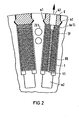
- Each of the individual coils Windings W thus consists of a partial conductor package TP, which is shown in Fig. 2 in section and Fig. 1 in the bale area b in the partially broken state.
- the partial conductor packs TP are secured by upper-side insulating material supplements Bel, by lateral insulating-material supplements Be2 and by groove closing parts K, which engage corresponding recesses nl of the groove flanks with wedge-shaped projections kl.
- the individual flat partial conductors t which are rectangular in cross section, are insulated from one another in their partial conductor package or stack and, seen over the bale length, are provided with radial bores tl which communicate with a basic groove channel n2, the latter extending over the axial bale length b in such a way that the Cooling gas flow for direct rotor conductor cooling, as indicated by arrow fl, can flow radially outward from the bottom of the groove through the cooling gas bores tl of the partial conductor t, through corresponding openings bell in the upper side groove inserts and through openings k2 in the slot closing wedges K into the air gap space LS.
- the warmed up cooling gas (in the case of an air-cooled machine, the warmed up cooling air) is sucked out of the air gap space via fans (not shown) at one or both machine ends, just as these fans push the cooling gas into the rotor cooling ducts from the two end faces of the rotor.
- toothed ducts ZK are also provided with axially extending duct sections zkl and duct sections zk2 branching radially therefrom, the cooling air also being able to pass radially from the latter into the air gap space LS.
- the radial channels RK resulting from the bores tl in the rotor winding conductors as well as the radial channels zk2 could also be oblique-radial run, but this means a higher manufacturing effort.
- the winding head designated as a whole by WK
- WK the winding head
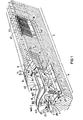
- This insulating material cylinder 1 of which only one arc piece can be seen in FIG. 1, now has cooling gas inlet openings 2 in the region of the transition from the axially extending longitudinal coil sides wkl to the peripherally extending coil front sides wk2 of the winding head WK (bending regions B).
- the annular gap between the inner circumference of the winding head WK, which is covered by the insulating material cylinder 1, and the outer circumference rll of the rotor shaft journal rl is designated by gkl. This annular gap is also the gas flow space in the end winding area w.
- the insulating cylinder 1 is held at its bale end by insertion into an annular groove 1.1; otherwise, the cylinder 1 is supported on the inside of the filler pieces 5.1, 5.2, which in turn, like the coil windings W of the winding head WK, are kept centrifugally safe on the inner circumference of the winding head cap (not shown).
- the inlet openings 2 are so large in their diameter or in their width that they communicate with winding head cooling channels gk2 from tangential spaces sp2 and with winding head cooling channels gk3 from axial gap spaces sp3.
- the former spaces sp2 are formed and delimited between the mutually adjacent, axially extending coil long sides wkl, the latter spaces sp3 are formed and delimited between the mutually adjacent, peripherally running coil end faces wk2 of the winding head WK.
- the already mentioned tangential gap fillers 5.1 and the axial gap fillers 5.2 are inserted into the tangential gap spaces sp2 and into the axial gap spaces sp3, which are supported on both sides with support surfaces 5.0 directly on the coil longitudinal or Coil end faces wkl, wk2 rest and are provided with recesses between their support surfaces 5.0 to form the winding head cooling channels gk2, gk3.
- winding head cooling channels are provided on both sides of the filler pieces 5.1, 5.2, which is expressed in that the gas flow arrows f2, f3 are drawn out on the (visible) wrapper piece side and the gas flow lines f2 on the side of the filler pieces 5.1, 5.2 facing away from the viewer ', f3' are shown in dashed lines.
- the winding head cooling channels gk2, gk3 run in a meandering or wave-like manner with changing radial height and in the main axial or peripheral direction along the axially running coil longitudinal sides or along the peripherally running coil front sides wkl or wk2, all the way to winding head cooling gas -Exhaust ducts gk4 or ZK.
- winding head cooling gas outlet channels ZK have already been mentioned. It can be seen that the winding head cooling channels gk2 open directly at their ends into the axially extending channel sections zkl of the outlet channels ZK. The temperature gradient that the cooling gas still has after leaving the winding head area w compared to the temperature of the bale area b is used to cool it before the cooling gas passes through the radial branch channels zk2 into the air gap space LS.
- Further winding head cooling gas outlet channels can additionally or instead be formed by outlet cross sections in the area of the cap end and insert ring by corresponding outlet cross sections between insert ring (not shown) and shaft journals, via which the cooling gas subsets can then flow from the outlet channel sections gk4 to the stator end winding space.
Landscapes
- Engineering & Computer Science (AREA)
- Power Engineering (AREA)
- Motor Or Generator Cooling System (AREA)
- Windings For Motors And Generators (AREA)
Abstract
Description
- Die Erfindung bezieht sich auf eine Einrichtung zur forcierten Gaskühlung der R otorwicklungen -dynamoelektrischer Maschinen, insbesondere von Turbogeneratoren, gemäß Oberbegriff des Anspruchs 1.
- Bei bekannten Einrichtungen zur Gaskühlung der Rotorwicklungen von Turbogeneratoren der genannten Art wird zwar die Rotcrwicklung in ihrem aktiven Teil (Nutbereich) sehr intensiv gekühlt. Jedoch werden im Vergleich dazu die in den Wickelkopfräumen entstehenden elektrischen Verlustleistungen nach der Methode der Thermosyphonkühlung abgeführt (siehe dazu Wissentschaftliche Berichte AEG-Telefunken 41 (1968) Heft 4, Seiten 161 bis 167, insbesondere Seite 161). Die Wirksamkeit dieser Kühlmethode ist in der Regel indessen geringer als die Kühlmethode im aktiven Teil, so daß der wärmste Punkt der Wicklung im Wickelkopfbereich liegt. Die Erwärmung des Wickelkopfes begrenzt mithin eine höhere Ausnutzung des Läufers oder eine Leistungssteigerung des Turbogenerator bzw. allgemein der dynamoelektrischen Maschine. Das Problem besteht nun darin, eine verbesserte Kühlung für die Wickelköpfe zu finden, die sowohl im Wickelkopfbereich als auch im aktiven Teil eine möglichst niedrige und gleichmäßige Übertemperatur erreicht. Erst dann könnte die gewünschte Leistungssteigerung oder höhere Ausnutzung erzielt werden.
- Der Erfindung liegt die Aufgabe zugrunde, eine gattungsgemäße Einrichtung zur forcierten Gaskühlung der Rotorwicklungen dynamoelektrischer Maschinen, insbesondere von Turbogeneratoren, zu schaffen, bei der die Intensität der Wickelkopfkühlung an diejenige der direkten Leiterkühlung im Ballenteil angeglichen werden kann, oder mit anderen Worten: Es soll die Wickelkopfgaskühlung so intensiviert sein, daß die durch die Kühlungsart (Luftkühlung, H2-Kühlung) der gasgekühlten Maschinen gegebenen Leistungsgrenzen nach oben erweitert werden können, weil die Wickelkopf-Übertemperatur nicht mehr die entscheidende Größe ist.
- Erfindungsgemäß wird die gestellte Aufgabe bei einer Einrichtung gemäß Oberbegriff des Anspruchs 1 durch die im Kennzeichen des Anspruchs 1 angegebenen Merkmale gelöst. Vorteilhafte Weiterbildungen sind in den Unteransprüchen 2 und 3 angegeben.
- Die mit der Erfindung erzielbaren Vorteile sind vor allem in der Intensivierung der Wickelkopfkühlung zu sehen; diese kann man als Vierflut-Kühlung bezeichnen, weil sowohl die axialen als auch die peripheren Spulenseiten des Wickelkopfes ihre eigenen Kühlgasströme haben, und dies an beiden Maschinenenden. Die neue Einrichtung läßt sich unschwer in Bezug auf den Kühleffekt an den Wickelköpfen optimieren: Die Spalten zwischen den Füllstücken und der Wickelkopfoberfläche können so gestaltet werden, daß die Übertemperatur am niedrigsten wird. D. h. es kann ein Kompromiß gefunden werden zwischen möglichst kleinen Spalten und größeren Spalten. Im erstgenannten Fall folgt aus der relativ hohen Kühlmittelgeschwindigkeit eine hohe Wärmeübergangszahl und eine kleine Temperaturdifferenz zwischen Wicklung und Kühlmittel; damit ist jedoch auch ein relativ großen Druckabfall verbunden, was wiederum zur Reduzierung der Kühlmittelmenge und zu einer höheren Kühlmittelaufwärmung führt. Im zweitgenannten Fall bei größeren Spalten ergibt sich eine kleinere Wärmeübergangszahl und daraus eine höhere Temperaturdifferenz zwischen der Wicklung und dem Kühlmittel, aber zugleich eine geringere Kühlmittelaufwärmung.
- Im folgenden wird anhand der Zeichnung, in der ein Ausführungsbeispiel der Erfindung dargestellt wird, diese noch näher erläutert. Darin zeigen:
- Fig. 1 perspektivisch im Ausschnitt die Rotorpartie eines Turbogenerators mit der Einrichtung zur forcierten Wickelkopf-Gaskühlung nach der Erfindung;
- Fig. 2 ein Querschnittsdetail des Rotorballens mit zwei Rotorwicklungsleiteranordnungen und
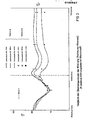
- Fig. 3 ein Diagramm, in dem vergleichsweise die Übertemperaturen der Wicklung zwischen gerechneten Werten und den an einem Läufermodell gemessenen Werten eingetragen sind, und zwar über einer axialen Teillänge von Wickelkopfmitte bis Ballenmitte gesehen (Abszissenachse). Details ergeben sich aus der Legende der Fig. 3.
- Wie Fig. 1 zeigt, sind in dem aus magnetischem Stahl bestehenden Rotor R Nuten N zum Einlegen der Spulenwindungen W der Rotorwicklung eingefräßt. Die Spulenwindungen W erstrecken sich innerhalb der Nuten N des Ballenbereiches b axial-radial; im Wickelkopfbereich w erstrecken sich die Windungen W zunächst auch axial-radial und sind dann an den Biegestellen B so abgebogen, daß sie peripher längs Umfangslinien verlaufeq. Diese peripher verlaufenden Spulenpartien werden dann zum Einfügen in weitere Nuten N wiederum in die Axiale umgebogen (nicht dargestellt). Jede der einzelnen Spulenwindungen W besteht somit aus einem Teilleiterpaket TP, welches in Fig. 2 im Schnitt und Fig. l im Ballenbereich b im teilweise weggebrochenen Zustand dargestellt ist. In ihrer in die Nut N eingelegten Lage werden die Teilleiterpakete TP durch oberseitige Isolierstoff-Beilagen Bel, durch seitliche Isolierstoffbeilagen Be2 und durch Nutverschlußteile K abgesichert, welche entsprechende Rücksprünge nl der Nutflanken mit keilförmigen Vorsprüngen kl hintergreifen. Die einzelnen flachen, im Querschnitt rechteckförmigen Teilleiter t sind in ihrrem Teilleiterpaket bzw. Stapel gegeneinander isoliert und über die Ballenlänge gesehen gleichmäßig verteilt mit Radialbohrungen tl versehen, welche mit einem Nutengrundkanal n2 kommunizieren, letzterer erstreckt sich über die- axiale Ballenlänge b derart, daß die Kühlgasströmung für die direkte Rotorleiterkühlung, wie es Pfeil fl andeutet, vom Nutengrund her durch die Kühlgasbohrungen tl der Teilleiter t radial nach außen, und zwar durch entsprechende Öffnungen bell der oberseitigen Nutbeilagen und durch Öffnungen k2 in den Nutverschlußkeilen K in den Luftspaltraum LS strömen kann. Aus dem Luftspaltraum LS wird das aufgewärmte Kühlgas (bei einer luftgekühlten Maschine also die aufgewärmte Kühlluft) über nicht dargestellte Ventilatoren an einem oder an beiden Maschinenenden abgesaugt, ebenso wie durch diese Ventilatoren das Kühlgas von den beiden Stirnseiten des Rotors her in die Rotorkühlkanäle hineingedrückt wird. Zur indirekten Rotorkühlung sind weiterhin Zahnkanäle ZK vorgesehen mit axial verlaufenden Kanalabschnitten zkl und radial davon abzweigenden Kanalabschnitten zk2, wobei aus letzteren die Kühlluft ebenfalls radial in den Luftspaltraum LS übertreten kann. Die durch die Bohrungen tl in den Rotorwicklungsleitern sich ergebenden Radialkanäle RK ebenso wie die Radialkanäle zk2 könnten auch schräg-radial verlaufen, was jedoch einen höheren Fertigungsaufwand bedeutet.
- Erfindungsgemäß ist nun der als Ganzes mit WK bezeichnete Wickelkopf an seinem inneren Umfang durch einen Isolierstoff-Zylinder 1 abgedeckt. Dieser Isolierstoff- Zylinder 1, von dem in Fig. 1 nur ein Bogenstück erkennbar ist, weist nun im Bereich des Überganges von den axial verlaufenden Spulenlängsseiten wkl zu den peripher verlaufenden Spulenstirnseiten wk2 des Wickelkopfes WK (Biegungsbereiche B) jeweils Kühlgas-Eintrittsöffnungen 2 auf.
- Der Ringspalt zwischen dem Innenumfang des Wickelkopfes WK, der ja durch den Isolierstoff-Zylinder 1 abgedeckt ist, und dem Außenumfang rll des Rotorwellenzapfens rl ist mit gkl bezeichnet. dieser Ringspalt ist zugleich der Gas-Strömungsraum im Wickelkopfbereich w. Die Halterung des Isolierstoff-zylinders 1 erfolgt an seinem ballenseitigen Ende durch Einfügung in eine Ringnut 1.1; im übrigen stützt sich der Zylinder 1 an der Innenseite der Füllstücke 5.1, 5.2 ab, welche wiederum ebenso wie die Spulenwindungen W des Wickelkopfes WK am Innenumfang der nicht dargestellten Wickelkopfkappe fliehkraftsich-er gehalten werden.
- Die Eintrittsöffnungen 2 sind in ihrem Durchmesser bzw. in ihrer Weite so groß, daß sie mit Wickelkopfkühlkanälen gk2 von Tangential-Räumen sp2 als auch mit Wickelkopf-Kühlkanälen gk3 von Axial-Spalt-Räumen sp3 kommunizieren. Erstere Räume sp2 werden gebildet und begrenzt zwischen den einander benachbarten, axial verlaυfenden Spulenlängsseiten wkl, letztere Räume sp3 werden gebildet und begrenzt zwischen den einander benachbarten, peripher verlaufenden Spulenstirnseiten wk2 des Wickelkopfes WK.
- Unter Freilassung der Wickelkopf-Kühlkanäle gk2 und gk3 sind nun in die Tangentialspalt-Räume sp2 und in die Axialspalt-Räume sp3 die schon erwähnten Tangentialspalt-Füllstücke 5.1 und die Axialspalt-Füllstücke 5.2 eingefügt, welche beidseits mit Stützflächen 5.0 unmittelbar an den Spulenlängs- bzw. Spulenstirnseiten wkl, wk2 anliegen und zwischen ihren Stützflächen 5.0 mit Aussparungen zur Bildung der Wickelkopf-Kühlkanäle gk2, gk3 versehen sind. Diese Wickelkopf-Kühlkanäle sind auf beiden Seiten der Füllstücke 5.1, 5.2 vorgesehen, was dadurch zum Ausdruck gebracht wird, daß auf der (sichtbaren) Hüllstückseite die Gasströmungspfeile f2, f3 ausgezogen und auf der dem Betrachter abgewandten Seite der Füllstücke 5.1, 5.2 die Gasströmungslinien f2', f3' gestrichelt dargestellt sind.
- Wie man erkennt, verlaufen die Wickelkopf-Kühlkanäle gk2, gk3 meander- oder wellenförmig mit sich ändernder radialer Höhe und in axialer bzw. peripherer Hauptrichtung an den axial verlaufenden Spulenlängsseiten bzw. an den peripher verlaufenden Spulenstirnseiten wkl bzw. wk2 entlang, bis hin zu Wickelkopfkühlgas-Auslaßkanälen gk4 bzw. ZK.
- Die letztgenannten Wickelkopfkühlgas-Auslaßkanäle ZK wurden bereits erwähnt. Man sieht, daß die Wickelkopf-Kühlkanäle gk2 an ihren Enden unmittelbar in die axial verlaufenden Kanalabschnitte zkl der Auslaßkanäle ZK münden. Damit wird das Temperaturgefälle, welches das Kühlgas nach Verlassen des Wickelkopfbereiches w im Vergleich zur Temperatur des Ballenbereiches b noch hat, zu dessen Kühlung ausgenutzt, bevor das Kühlgas über die radialen Abzweigkanäle zk2 in den Luftspaltraum LS übertritt.
- Eine zweite Gruppe von Wickelkopfkühlgas-Auslaßkanälen kommuniziert mit den Wickelkopf-Kühlkanälen gk3 der peripheren Hauptrichtung und wird gebildet durch:
- Etwa in Wickelkopf-Mitte wk0 angeordnete Auslaßöffnungen 3 im Isolierstoffzylinder;
- einen sich daran anschließenden zwischen Wickelkopf-Innenumfang und Wellenzapfen rl angeordneten, mittels Radialwänden 4 abgeschotteten und sich axial erstreckenden Auslaßkanalabschnitt gk4 (wurde bereits erwähnt) und
- am ballenseitigen Ende (siehe Ballenanfang b0) des Auslaßkanalabschnittes gk4 im Polendbereich vorgesehene Auslaßmündungen 6, deren ungefähre Lage gestrichelt angedeutet ist. Von diesen Auslaßmündungen 6 des Auslaßkanalabschnittes gk4, welche durch entsprechende Öffnungen im Isolierstoff-Zylinder 1 gebildet werden, strömen die Kühlgasteilmengen gemäß Pfeilen f4 etwa radial in den Luftspalt ab.
- Weitere Wickelkopfkühlgas-Auslaßkanäle können zusätzlich dazu oder anstelle dessen gebildet sein durch Auslaßquerschnitte im Bereich des Kappenendes und Einsatzringes durch entsprechende Auslaßquerschnitte zwischen Einsatzring (nicht dargestellt) und Wellenzapfen, über welche dann die Kühlgas-Teilmengen von den Auslaßkanalabschnitten gk4 zum Ständerwickelkopfraum strömen können.
- Mit Hilfe der beschriebenen Einrichtung nach der Erfindung ist es gelungen, wie es durch Fig. 3 verdeutlicht wird, die Ubertemperaturen des Wickelkopfes auf das niedrigere Niveau der Übertemperaturen des.aktiven Teiles zu senken. Damit ist eine höhere Ausnutzung des Rotors ohne Schwierigkeiten möglich. Ebenso kann auf Grund dieser intensivierten Kühlung bei entsprechender Gestaltung des Ständers die Leistung des Turbogenerators bzw. der dynamoelektrischen Maschine gesteigert werden.
Claims (3)
gekennzeichnet durch
die folgenden Merkmale:
Priority Applications (1)
| Application Number | Priority Date | Filing Date | Title |
|---|---|---|---|
| AT85104985T ATE55516T1 (de) | 1984-05-08 | 1985-04-24 | Einrichtung zur forcierten rotorwicklungsgask¨hlung dynamoelektrischer maschinen, insbesondere von turbogeneratoren. |
Applications Claiming Priority (2)
| Application Number | Priority Date | Filing Date | Title |
|---|---|---|---|
| DE19843416943 DE3416943A1 (de) | 1984-05-08 | 1984-05-08 | Einrichtung zur forcierten rotorwicklungs-gaskuehlung dynamoelektrischer maschinen, insbesondere von turbogeneratoren |
| DE3416943 | 1984-05-08 |
Publications (3)
| Publication Number | Publication Date |
|---|---|
| EP0160887A2 true EP0160887A2 (de) | 1985-11-13 |
| EP0160887A3 EP0160887A3 (en) | 1986-11-05 |
| EP0160887B1 EP0160887B1 (de) | 1990-08-08 |
Family
ID=6235220
Family Applications (1)
| Application Number | Title | Priority Date | Filing Date |
|---|---|---|---|
| EP85104985A Expired - Lifetime EP0160887B1 (de) | 1984-05-08 | 1985-04-24 | Einrichtung zur forcierten Rotorwicklungs-Gaskühlung dynamoelektrischer Maschinen, insbesondere von Turbogeneratoren |
Country Status (4)
| Country | Link |
|---|---|
| EP (1) | EP0160887B1 (de) |
| AT (1) | ATE55516T1 (de) |
| DE (2) | DE3416943A1 (de) |
| IN (1) | IN163951B (de) |
Cited By (7)
| Publication number | Priority date | Publication date | Assignee | Title |
|---|---|---|---|---|
| DE3700508A1 (de) * | 1987-01-09 | 1988-07-21 | Siemens Ag | Einrichtung zur gaskuehlung des wickelkopfbereiches von rotorwicklungen dynamoelektrischer maschinen |
| DE4021861A1 (de) * | 1990-07-09 | 1992-01-16 | Siemens Ag | Gasgekuehlter laeufer einer elektromaschine mit erhoehter variabilitaet der kuehlwege durch multifunktionsleiter |
| US5454162A (en) * | 1991-04-29 | 1995-10-03 | Siemens Aktiengesellschaft | Method of making electrical conductor with a longitudinal groove and slots perpendicular thereto |
| EP1850458A3 (de) * | 2006-04-28 | 2011-04-13 | Kabushiki Kaisha Toshiba | Laufer für dynamo-elektrische Maschine |
| WO2012134328A1 (ru) | 2011-04-01 | 2012-10-04 | Закрытое Акционерное Общество "Нефтьс-Тальконструкция" | Система вентиляции ротора электрической машины |
| EP3200322A1 (de) * | 2016-01-28 | 2017-08-02 | General Electric Technology GmbH | Rotor für eine elektrische maschine |
| WO2020064802A1 (de) * | 2018-09-27 | 2020-04-02 | Siemens Aktiengesellschaft | Verblockungselement für rotorwickelköpfe bei turbogeneratoren mit läuferkappe mit radialen ventilationsbohrungen |
Families Citing this family (2)
| Publication number | Priority date | Publication date | Assignee | Title |
|---|---|---|---|---|
| HUP9901284A3 (en) * | 1996-04-17 | 1999-11-29 | Siemens Ag | Rotor winding for an electric machine |
| DE102009042706A1 (de) | 2009-09-24 | 2011-04-07 | Sensoplan Aktiengesellschaft | Sanierverfahren für die Leiter eines Rotors eines elektrischen Generators |
Family Cites Families (3)
| Publication number | Priority date | Publication date | Assignee | Title |
|---|---|---|---|---|
| DE274467C (de) * | ||||
| US2459586A (en) * | 1947-05-13 | 1949-01-18 | Westinghouse Electric Corp | Rotor ventilation for turbogenerators |
| US3322985A (en) * | 1965-05-05 | 1967-05-30 | Azbukin Jury Ivanovich | Gas-cooled rotor of electric generator |
-
1984
- 1984-05-08 DE DE19843416943 patent/DE3416943A1/de not_active Withdrawn
-
1985
- 1985-04-24 DE DE8585104985T patent/DE3579029D1/de not_active Expired - Lifetime
- 1985-04-24 EP EP85104985A patent/EP0160887B1/de not_active Expired - Lifetime
- 1985-04-24 AT AT85104985T patent/ATE55516T1/de not_active IP Right Cessation
- 1985-05-06 IN IN349/CAL/85A patent/IN163951B/en unknown
Cited By (9)
| Publication number | Priority date | Publication date | Assignee | Title |
|---|---|---|---|---|
| DE3700508A1 (de) * | 1987-01-09 | 1988-07-21 | Siemens Ag | Einrichtung zur gaskuehlung des wickelkopfbereiches von rotorwicklungen dynamoelektrischer maschinen |
| DE4021861A1 (de) * | 1990-07-09 | 1992-01-16 | Siemens Ag | Gasgekuehlter laeufer einer elektromaschine mit erhoehter variabilitaet der kuehlwege durch multifunktionsleiter |
| US5454162A (en) * | 1991-04-29 | 1995-10-03 | Siemens Aktiengesellschaft | Method of making electrical conductor with a longitudinal groove and slots perpendicular thereto |
| US5468907A (en) * | 1991-04-29 | 1995-11-21 | Siemens Aktiengesellschaft | Electrical conductor with a longitudinal groove and slots perpendicular thereto and a method for producing the same |
| EP1850458A3 (de) * | 2006-04-28 | 2011-04-13 | Kabushiki Kaisha Toshiba | Laufer für dynamo-elektrische Maschine |
| WO2012134328A1 (ru) | 2011-04-01 | 2012-10-04 | Закрытое Акционерное Общество "Нефтьс-Тальконструкция" | Система вентиляции ротора электрической машины |
| EP3200322A1 (de) * | 2016-01-28 | 2017-08-02 | General Electric Technology GmbH | Rotor für eine elektrische maschine |
| WO2020064802A1 (de) * | 2018-09-27 | 2020-04-02 | Siemens Aktiengesellschaft | Verblockungselement für rotorwickelköpfe bei turbogeneratoren mit läuferkappe mit radialen ventilationsbohrungen |
| US11876418B2 (en) | 2018-09-27 | 2024-01-16 | Siemens Energy Global GmbH & Co. KG | Blocking element for rotor winding heads on turbogenerators with rotor cap with radial ventilation bores |
Also Published As
| Publication number | Publication date |
|---|---|
| DE3579029D1 (de) | 1990-09-13 |
| DE3416943A1 (de) | 1985-11-14 |
| IN163951B (de) | 1988-12-17 |
| EP0160887B1 (de) | 1990-08-08 |
| EP0160887A3 (en) | 1986-11-05 |
| ATE55516T1 (de) | 1990-08-15 |
Similar Documents
| Publication | Publication Date | Title |
|---|---|---|
| EP0155405B1 (de) | Einrichtung zur indirekten Gaskühlung der Ständerwicklung und/oder zur direkten Gaskühlung des Ständerblechpaketes dynamoelektrischer Maschinen, vorzugsweise für gasgekühlte Turbogeneratoren | |
| EP0279064B1 (de) | Gasgekühlte elektrische Maschine | |
| DE102021113440A1 (de) | Stator einer elektrischen Maschine, Verfahren zum Herstellen desselben und elektrische Maschine | |
| EP4193450B1 (de) | Windkraftanlage mit zumindest einer dynamoelektrischen maschine | |
| DE2511104C3 (de) | Kuhlanordnung für eine supraleitende Erregerwicklung | |
| DE112015003443T5 (de) | Fluidgekühlte gewundene Streifenstruktur | |
| DE4312217A1 (de) | Halbspulenkonfiguration für Statoren | |
| DE19645272A1 (de) | Gasgekühlte elektrische Maschine | |
| CH323433A (de) | Verfahren und Einrichtung zum Kühlen von elektrischen Leitern einer ganz gekapselten, dynamoelektrischen Maschine | |
| EP0894358B1 (de) | Rotorwicklung für eine elektrische maschine | |
| DE3015435C2 (de) | Schenkelpol-Synchronmaschine | |
| DE1488784A1 (de) | Hochleistungssynchronmaschine mit hoher mittlerer Induktion im Luftspalt | |
| EP0160887B1 (de) | Einrichtung zur forcierten Rotorwicklungs-Gaskühlung dynamoelektrischer Maschinen, insbesondere von Turbogeneratoren | |
| DE2235336A1 (de) | Fluessigkeitsgekuehlter rotor fuer dynamoelektrische maschinen | |
| DE112022007711T5 (de) | Stator einer elektrischen Maschine mit inneren Kühlkanälen | |
| EP0172397A1 (de) | Elektrische Maschine mit indirekt gekühlter Statorwicklung | |
| DE2524820A1 (de) | Dynamoelektrische maschine | |
| DE102020109482B4 (de) | Verfahren zum Herstellen eines Stators für eine elektrische Maschine, entsprechender Stator sowie Verfahren zum Betreiben einer elektrischen Maschine, entsprechender Stator sowie Verfahren zum Betreiben einer elektrischen Maschine | |
| DE2526290A1 (de) | Dynamomaschine mit kuehlfluessigkeitsrotor | |
| DE1013771B (de) | Gasgekuehlte dynamoelektrische Maschine | |
| EP1204193B1 (de) | Kühlsystem für trägheitsarme rotierende elektrische Maschine | |
| WO2024184096A1 (de) | Elektrische maschine für ein kraftfahrzeug | |
| DE1463852B2 (de) | Indirekt flüssigkeitsgekühlte, aus Volleitern bestehende Läuferwicklung einer elektrischen Maschine mit Schenkelpolläufer | |
| EP1062719A1 (de) | Belüftungssystem für die erregerwicklung grosser schenkelpolmaschinen | |
| DD144484A1 (de) | Kuehlkanal im staender-und laeuferblechpaket elektrischer maschinen |
Legal Events
| Date | Code | Title | Description |
|---|---|---|---|
| PUAI | Public reference made under article 153(3) epc to a published international application that has entered the european phase |
Free format text: ORIGINAL CODE: 0009012 |
|
| AK | Designated contracting states |
Designated state(s): AT CH DE FR GB LI |
|
| PUAL | Search report despatched |
Free format text: ORIGINAL CODE: 0009013 |
|
| AK | Designated contracting states |
Kind code of ref document: A3 Designated state(s): AT CH DE FR GB LI |
|
| 17P | Request for examination filed |
Effective date: 19870127 |
|
| RAP1 | Party data changed (applicant data changed or rights of an application transferred) |
Owner name: SIEMENS AKTIENGESELLSCHAFT BERLIN UND MUENCHEN |
|
| 17Q | First examination report despatched |
Effective date: 19890822 |
|
| GRAA | (expected) grant |
Free format text: ORIGINAL CODE: 0009210 |
|
| AK | Designated contracting states |
Kind code of ref document: B1 Designated state(s): AT CH DE FR GB LI |
|
| REF | Corresponds to: |
Ref document number: 55516 Country of ref document: AT Date of ref document: 19900815 Kind code of ref document: T |
|
| REF | Corresponds to: |
Ref document number: 3579029 Country of ref document: DE Date of ref document: 19900913 |
|
| ET | Fr: translation filed | ||
| GBT | Gb: translation of ep patent filed (gb section 77(6)(a)/1977) | ||
| PLBE | No opposition filed within time limit |
Free format text: ORIGINAL CODE: 0009261 |
|
| STAA | Information on the status of an ep patent application or granted ep patent |
Free format text: STATUS: NO OPPOSITION FILED WITHIN TIME LIMIT |
|
| 26N | No opposition filed | ||
| PGFP | Annual fee paid to national office [announced via postgrant information from national office to epo] |
Ref country code: GB Payment date: 19970321 Year of fee payment: 13 |
|
| PGFP | Annual fee paid to national office [announced via postgrant information from national office to epo] |
Ref country code: AT Payment date: 19970326 Year of fee payment: 13 |
|
| PGFP | Annual fee paid to national office [announced via postgrant information from national office to epo] |
Ref country code: FR Payment date: 19970422 Year of fee payment: 13 |
|
| PGFP | Annual fee paid to national office [announced via postgrant information from national office to epo] |
Ref country code: DE Payment date: 19970617 Year of fee payment: 13 |
|
| PGFP | Annual fee paid to national office [announced via postgrant information from national office to epo] |
Ref country code: CH Payment date: 19970715 Year of fee payment: 13 |
|
| PG25 | Lapsed in a contracting state [announced via postgrant information from national office to epo] |
Ref country code: GB Free format text: LAPSE BECAUSE OF NON-PAYMENT OF DUE FEES Effective date: 19980424 Ref country code: AT Free format text: LAPSE BECAUSE OF NON-PAYMENT OF DUE FEES Effective date: 19980424 |
|
| PG25 | Lapsed in a contracting state [announced via postgrant information from national office to epo] |
Ref country code: LI Free format text: LAPSE BECAUSE OF NON-PAYMENT OF DUE FEES Effective date: 19980430 Ref country code: FR Free format text: THE PATENT HAS BEEN ANNULLED BY A DECISION OF A NATIONAL AUTHORITY Effective date: 19980430 Ref country code: CH Free format text: LAPSE BECAUSE OF NON-PAYMENT OF DUE FEES Effective date: 19980430 |
|
| REG | Reference to a national code |
Ref country code: CH Ref legal event code: PL |
|
| GBPC | Gb: european patent ceased through non-payment of renewal fee |
Effective date: 19980424 |
|
| PG25 | Lapsed in a contracting state [announced via postgrant information from national office to epo] |
Ref country code: DE Free format text: LAPSE BECAUSE OF NON-PAYMENT OF DUE FEES Effective date: 19990202 |
|
| REG | Reference to a national code |
Ref country code: FR Ref legal event code: ST |