EP0160892B1 - Capsule de ressort - Google Patents
Capsule de ressort Download PDFInfo
- Publication number
- EP0160892B1 EP0160892B1 EP85105010A EP85105010A EP0160892B1 EP 0160892 B1 EP0160892 B1 EP 0160892B1 EP 85105010 A EP85105010 A EP 85105010A EP 85105010 A EP85105010 A EP 85105010A EP 0160892 B1 EP0160892 B1 EP 0160892B1
- Authority
- EP
- European Patent Office
- Prior art keywords
- spring
- cap
- mounting plate
- end section
- helical spring
- Prior art date
- Legal status (The legal status is an assumption and is not a legal conclusion. Google has not performed a legal analysis and makes no representation as to the accuracy of the status listed.)
- Expired - Lifetime
Links
Images


Classifications
-
- B—PERFORMING OPERATIONS; TRANSPORTING
- B60—VEHICLES IN GENERAL
- B60R—VEHICLES, VEHICLE FITTINGS, OR VEHICLE PARTS, NOT OTHERWISE PROVIDED FOR
- B60R22/00—Safety belts or body harnesses in vehicles
- B60R22/34—Belt retractors, e.g. reels
Definitions
- the invention relates to a spring capsule for a seat belt winding device with a belt winding shaft rotatably mounted between the side parts of a U-shaped angled base plate, the spring capsule being a bearing plate to be attached to the side part of the base plate with a central opening, a cover cap and a spiral spring arranged between them for engagement with the end portion of the winding shaft passing through the opening of the bearing plate.
- a spring capsule is known from US-A-4,285,478.
- a bearing plate is mounted on a side part of the base plate, through the central opening of which the end section of the winding shaft, which is provided with a continuous slot, protrudes.
- the bearing plate has an irregularly shaped wall web, in the area of which a holding device is provided for the outer end section of the spiral spring which is used to automatically wind up the seat belt.
- the spiral spring is inserted with its inner end section into the continuous slot of the winding shaft end section and with its outer end section into the holder device after attachment of the bearing plate.
- a cover cap which overlaps the bearing plate and the spiral spring, is then attached and screwed to the side part of the base plate.
- the winding device assembled in this way is secured when the coil spring is tensioned by inserting a special transport hook that blocks the rotation of the winding shaft and is stored until the belt is installed.
- the spiral spring is mounted on the bearing plate and the winding shaft by hand, which is not only time-consuming, but also to a considerable extent prone to accidents.
- the intermediate storage of the winder in tense coil spring has on the one hand an unnecessary fatigue of the spring before the actual use of the winder, on the other hand increased costs because of the need of Transportha - ken, which must also be installed by hand, result.
- the object of the invention is therefore to provide a spring capsule of the type mentioned, which is simple and safe to manufacture with reduced manufacturing and assembly costs and avoids fatigue of the coil spring before starting the winding device.
- the spring capsule of the type mentioned is equipped according to the invention with the features specified in the characterizing part of claim 1.
- An advantage of the spring capsule according to the invention is that it can be prefabricated as an independent unit with a non-tensioned spiral spring and can be stored independently of the winding device.
- the spring capsule can be placed on the assembled winding device, the spiral spring engaging with the winding shaft. After fixing the spring capsule on the winding device, the spiral spring is tensioned by rotating the cover cap relative to the bearing plate, whereupon the cover cap is fixed in a fixed position relative to the bearing plate.
- the design of the spring capsule with interlocking, mutually rotatable annular wall webs of the bearing plate and cover cap allows the opposite circumferential surfaces of the wall webs to be equipped with locking elements which prevent rotation, so that the spring capsule mounted on the winding device winds up in the manner of a clockwork to the desired tension of the coil spring leaves.
- the spring capsule shown in its individual parts in FIGS. 1 to 5 is attached to a seat belt winding device which has a U-shaped angled base plate, between the side parts of which a winding shaft for the seat belt is rotatably mounted.
- the end portions of the take-up shaft each protrude above the outer surfaces of the base plate side parts, an end portion of the take-up shaft being connected to a reel-blocking device preventing the unwanted unwinding of the seat belt and the outer surface of the other side part being used to attach the spring capsule.
- the spiral spring 4 contained in the spring capsule is used for the automatic winding of the seat belt. It also has a not inconsiderable pretension in the fully wound position of the belt and is further tensioned when it is unwound.
- the spring capsule comprises a cover cap 1 with an annular outer wall web 2 in which two adjacent slots 3 are provided for fixing the outer end section 8 of the spiral spring 4.
- the outer end portion 8 of the coil spring 4 is guided from the inside out and back through the slots 3 and so in. Pinch held.
- the spiral spring 4 is in the interior of the cover 1 enclosed by the wall web 2 and has an annular ge closed inner end portion 6, which is pushed over a central centering projection 5 of the cap 1 and can rotate on this.
- the spring capsule further comprises the bearing plate 9 shown in Figure 3, which has two holes 10 for attachment to the winding device and also has a substantially annular outer wall web 11, the diameter of which is so much larger than that of the wall web 2 of the cap 1 that the Push the wall web 2 of the cap 1 concentrically into the wall web 11 of the bearing plate 9 and can rotate it in relation to it.
- the bearing plate 9 has a central opening 12.
- the spiral spring 4 is inserted into the cover cap 1 in the slightly tensioned wound state, its inner end section 6 being pushed over the central centering projection 5 and its outer end section 8 being fixed in the slots 3 of the wall web 2.
- the wall web 2 of the cover cap 1 is then inserted concentrically into the space enclosed by the wall web 11 of the bearing plate 9. In this state, the spring capsule can be stored until it is attached to the winding device.
- the spring capsule For assembly on the winding device, the spring capsule is pushed onto the end section 15 of the winding shaft 14 which is shown schematically in FIGS. 4a and 4b and projects beyond the outer surface of the base plate side part in such a way that the end section 15 protrudes through the opening 12 of the bearing plate 9 into the spring capsule .
- the end section 15 of the winding shaft 15 has, as shown in FIGS. 4a and 4b, three driving claws 16 which are arranged in the ring on the end face of the winding shaft 14.
- Each driver claw 16 has an axially sloping edge surface 17 which runs in the circumferential direction and extends in the direction of an adjacent driver claw and turns the steep edge driver surface 19 toward the curved edge surface tapering towards it from the other adjacent driver claw.
- the annular closed inner end section 6 of the spiral spring 4 is inserted through the central centering projection 5 of the cover cap 1 into the space lying within the annularly arranged driving claws 16 of the winding shaft 14.
- the area of the spiral spring 4 directly adjoining the end section 6 engages with one of the driver claws 16 and is guided through the curved edge surface 17 to bear against one of the axial driver surfaces 19.
- the inner end section 6 of the spiral spring 4 is freely rotatable with respect to the centering projection 5 of the cover cap 1, but after assembly has taken place, it is in a non-positive engagement with the winding shaft 14 and, furthermore, the outer end section 8 of the spiral spring 4 is connected in a clamped manner to the wall web 2 of the cover cap 1 the spring force acts between the cover cap 1 and the winding shaft 14.
- the Aufspulwei ie 14 can therefore be placed under spring force when the cap 1 is rotated in the tension direction of the coil spring 4. During this rotation, the tongues 13 of the wall web 11 of the bearing plate i pointing in the direction of the final tension of the spiral spring 4 slide on the outer circumference of the wall web 2 of the cover cap 1 and pass through the recesses 7 provided therein in a resilient manner.
- a return rotation of the cover cap 1 with respect to the bearing plate 9 under the tension of the spiral spring 4 is only possible by at most approximately a quarter turn until the tongues 13 each enter a recess 7 and block a further return rotation.
- the recesses 7 do not extend over the full axial height of the wall web 2 of the cap 1; the axial height of the tongues 13 is dimensioned accordingly. Axial slipping out of the cap 1 from the bearing plate 9 is therefore not possible when the tongues 13 engage in the recesses 7.
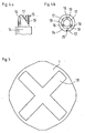
- a flat depression 18 is provided on the outer surface of the cover cap 1 shown in FIG Rotation of the cap 1 on.
- special turning tool is to be used.
- the axial depth of the recess 18 can be dimensioned such that when the torque corresponding to the desired spring tension is reached, the edges of the recess 18 are unscrewed and a further increase in the spring tension is thus excluded.
- a correspondingly flat elevation or a circumferential profile serving to rotate the cover cap 1 can also be provided.
Landscapes
- Engineering & Computer Science (AREA)
- Mechanical Engineering (AREA)
- Automotive Seat Belt Assembly (AREA)
- Pens And Brushes (AREA)
- Ink Jet (AREA)
- Devices For Conveying Motion By Means Of Endless Flexible Members (AREA)
- Medicinal Preparation (AREA)
- Springs (AREA)
Claims (6)
Priority Applications (1)
| Application Number | Priority Date | Filing Date | Title |
|---|---|---|---|
| AT85105010T ATE49386T1 (de) | 1984-05-09 | 1985-04-25 | Federkapsel. |
Applications Claiming Priority (2)
| Application Number | Priority Date | Filing Date | Title |
|---|---|---|---|
| DE3417029A DE3417029A1 (de) | 1984-05-09 | 1984-05-09 | Federkapsel |
| DE3417029 | 1984-05-09 |
Publications (3)
| Publication Number | Publication Date |
|---|---|
| EP0160892A2 EP0160892A2 (fr) | 1985-11-13 |
| EP0160892A3 EP0160892A3 (en) | 1987-06-03 |
| EP0160892B1 true EP0160892B1 (fr) | 1990-01-10 |
Family
ID=6235275
Family Applications (1)
| Application Number | Title | Priority Date | Filing Date |
|---|---|---|---|
| EP85105010A Expired - Lifetime EP0160892B1 (fr) | 1984-05-09 | 1985-04-25 | Capsule de ressort |
Country Status (3)
| Country | Link |
|---|---|
| EP (1) | EP0160892B1 (fr) |
| AT (1) | ATE49386T1 (fr) |
| DE (2) | DE3417029A1 (fr) |
Families Citing this family (3)
| Publication number | Priority date | Publication date | Assignee | Title |
|---|---|---|---|---|
| FR2600602B1 (fr) * | 1986-06-24 | 1990-03-09 | Peugeot Aciers Et Outillage | Barillet pour ressort spiral prebande et son application a un enrouleur de ceinture de securite notamment pour vehicule automobile terrestre |
| DE20118739U1 (de) * | 2001-11-16 | 2002-01-24 | Autoliv Development Ab, Vargarda | Wickelfeder-Befestigung bei einem Sicherheitsgurtaufroller |
| DE10319718A1 (de) * | 2003-05-02 | 2004-11-25 | Autoliv Development Ab | Verbindungsanordnung an einem Gurtaufwickelautomaten mit einer Gurtstraffvorrichtung |
Family Cites Families (6)
| Publication number | Priority date | Publication date | Assignee | Title |
|---|---|---|---|---|
| DE550810C (de) * | 1932-05-20 | Thiel G M B H Geb | Federhaus mit Aufzug fuer mechanische Uhrwerkszeitzuender | |
| US3305103A (en) * | 1965-05-12 | 1967-02-21 | Hollis R Hilstrom | Device for feeding a work piece into a fabricating machine |
| US3787002A (en) * | 1970-10-20 | 1974-01-22 | Tokai Rika Co Ltd | Emergency locking device for safety seat belt used in motor vehicles and the like |
| US4159809A (en) * | 1978-01-06 | 1979-07-03 | American Safety Equipment Corporation | Prewound retractor spring housing assembly |
| US4285478A (en) * | 1979-07-06 | 1981-08-25 | American Safety Equipment Corporation | Seat belt retractor mechanism housing |
| DE3116835A1 (de) * | 1980-05-20 | 1982-02-25 | Barnes Group Inc., 06010 Bristol, Conn. | Gurtaufroller |
-
1984
- 1984-05-09 DE DE3417029A patent/DE3417029A1/de active Granted
-
1985
- 1985-04-25 AT AT85105010T patent/ATE49386T1/de active
- 1985-04-25 EP EP85105010A patent/EP0160892B1/fr not_active Expired - Lifetime
- 1985-04-25 DE DE8585105010T patent/DE3575286D1/de not_active Expired - Lifetime
Also Published As
| Publication number | Publication date |
|---|---|
| ATE49386T1 (de) | 1990-01-15 |
| EP0160892A3 (en) | 1987-06-03 |
| EP0160892A2 (fr) | 1985-11-13 |
| DE3417029C2 (fr) | 1989-12-14 |
| DE3417029A1 (de) | 1985-11-14 |
| DE3575286D1 (de) | 1990-02-15 |
Similar Documents
| Publication | Publication Date | Title |
|---|---|---|
| DE2913812C2 (de) | Bandkassetten-behaelter zur verwahrung einer bandkassette | |
| DE2900104C2 (de) | Gehäusezusammenstellung für eine vorgespannte Feder einer Sicherheitsgurteinziehvorrichtung | |
| DE2613013A1 (de) | Absperrbarer verschluss fuer einen mit gewinde versehenen fuellstutzen | |
| DE2434847B2 (fr) | ||
| DE3605821A1 (de) | Schnellspannmutter, insbesondere zur befestigung eines fahrzeugrades auf der aufspannwelle einer auswuchtmaschine | |
| DE19852975C2 (de) | Spannungsreduzierer zum Entlasten der Zugkraft einer Aufrollvorrichtung für einen Sicherheitsgurt | |
| DE19933124A1 (de) | Endverschluß | |
| EP0310777B1 (fr) | Enjoliveur pour roue de véhicule | |
| EP0160892B1 (fr) | Capsule de ressort | |
| DE69601959T2 (de) | Montagevorrichtung für Rad und mit Laufrädern versehener, mit solcher Vorrichtung ausgerüsteter, Müllsammelbehälter | |
| DE19741691C2 (de) | Trommel für wickelbare Antriebselemente in Verstelleinrichtungen von Kraftfahrzeugen | |
| DE2824330C3 (de) | Spulenanordnung für Bandgeräte | |
| DE29511347U1 (de) | Radkappe für Kraftfahrzeuge | |
| EP0771702B1 (fr) | Rétracteur actionné par ressort pour ceintures de sécurité | |
| EP0180883B1 (fr) | Dispositif de bobinage d'un câble | |
| EP1026039B1 (fr) | Enrouleur pour une bande d'un dispositif de retenue de véhicule ou similaire, p.e. pour breaks | |
| DE2938573C2 (de) | Kabelaufroller | |
| DE3722604C2 (de) | Wendevorrichtung für Rafflamellenstores | |
| DE8507211U1 (de) | Gurtaufroller für Fahrzeugsicherheitsgurte | |
| EP0063313A1 (fr) | Dispositif d'enroulement de câbles | |
| DE2128055A1 (de) | In ein Aufwickelgehäuse einsetzbare Austauschkassette nebst Maßband für ein Taschenbandmaß | |
| EP0694674B1 (fr) | Dispositif d'entraínement électrique pour sangles | |
| DE2622810C3 (de) | Selbstsperrende Aufwickelvorrichtung für Sicherheitsgurte | |
| DE29703665U1 (de) | Wickelwelle für ein Sicherheitsgurtband | |
| CH640673A5 (en) | Cable reel |
Legal Events
| Date | Code | Title | Description |
|---|---|---|---|
| PUAI | Public reference made under article 153(3) epc to a published international application that has entered the european phase |
Free format text: ORIGINAL CODE: 0009012 |
|
| AK | Designated contracting states |
Designated state(s): AT BE DE FR GB IT NL SE |
|
| PUAL | Search report despatched |
Free format text: ORIGINAL CODE: 0009013 |
|
| AK | Designated contracting states |
Kind code of ref document: A3 Designated state(s): AT BE DE FR GB IT NL SE |
|
| 17P | Request for examination filed |
Effective date: 19871121 |
|
| 17Q | First examination report despatched |
Effective date: 19890606 |
|
| GRAA | (expected) grant |
Free format text: ORIGINAL CODE: 0009210 |
|
| AK | Designated contracting states |
Kind code of ref document: B1 Designated state(s): AT BE DE FR GB IT NL SE |
|
| PG25 | Lapsed in a contracting state [announced via postgrant information from national office to epo] |
Ref country code: SE Effective date: 19900110 Ref country code: NL Effective date: 19900110 Ref country code: IT Free format text: LAPSE BECAUSE OF FAILURE TO SUBMIT A TRANSLATION OF THE DESCRIPTION OR TO PAY THE FEE WITHIN THE PRESCRIBED TIME-LIMIT;WARNING: LAPSES OF ITALIAN PATENTS WITH EFFECTIVE DATE BEFORE 2007 MAY HAVE OCCURRED AT ANY TIME BEFORE 2007. THE CORRECT EFFECTIVE DATE MAY BE DIFFERENT FROM THE ONE RECORDED. Effective date: 19900110 Ref country code: BE Effective date: 19900110 |
|
| REF | Corresponds to: |
Ref document number: 49386 Country of ref document: AT Date of ref document: 19900115 Kind code of ref document: T |
|
| REF | Corresponds to: |
Ref document number: 3575286 Country of ref document: DE Date of ref document: 19900215 |
|
| ET | Fr: translation filed | ||
| GBT | Gb: translation of ep patent filed (gb section 77(6)(a)/1977) | ||
| PG25 | Lapsed in a contracting state [announced via postgrant information from national office to epo] |
Ref country code: AT Effective date: 19900425 |
|
| NLV1 | Nl: lapsed or annulled due to failure to fulfill the requirements of art. 29p and 29m of the patents act | ||
| PGFP | Annual fee paid to national office [announced via postgrant information from national office to epo] |
Ref country code: DE Payment date: 19900629 Year of fee payment: 6 |
|
| PLBE | No opposition filed within time limit |
Free format text: ORIGINAL CODE: 0009261 |
|
| STAA | Information on the status of an ep patent application or granted ep patent |
Free format text: STATUS: NO OPPOSITION FILED WITHIN TIME LIMIT |
|
| 26N | No opposition filed | ||
| PG25 | Lapsed in a contracting state [announced via postgrant information from national office to epo] |
Ref country code: DE Effective date: 19920201 |
|
| PGFP | Annual fee paid to national office [announced via postgrant information from national office to epo] |
Ref country code: FR Payment date: 20010409 Year of fee payment: 17 |
|
| PGFP | Annual fee paid to national office [announced via postgrant information from national office to epo] |
Ref country code: GB Payment date: 20010425 Year of fee payment: 17 |
|
| REG | Reference to a national code |
Ref country code: GB Ref legal event code: IF02 |
|
| PG25 | Lapsed in a contracting state [announced via postgrant information from national office to epo] |
Ref country code: GB Free format text: LAPSE BECAUSE OF NON-PAYMENT OF DUE FEES Effective date: 20020425 |
|
| GBPC | Gb: european patent ceased through non-payment of renewal fee |
Effective date: 20020425 |
|
| PG25 | Lapsed in a contracting state [announced via postgrant information from national office to epo] |
Ref country code: FR Free format text: LAPSE BECAUSE OF NON-PAYMENT OF DUE FEES Effective date: 20021231 |
|
| REG | Reference to a national code |
Ref country code: FR Ref legal event code: ST |