EP0160893A2 - Dispositif pour joindre une première partie avec une deuxième partie d'un membre tendu - Google Patents
Dispositif pour joindre une première partie avec une deuxième partie d'un membre tendu Download PDFInfo
- Publication number
- EP0160893A2 EP0160893A2 EP85105014A EP85105014A EP0160893A2 EP 0160893 A2 EP0160893 A2 EP 0160893A2 EP 85105014 A EP85105014 A EP 85105014A EP 85105014 A EP85105014 A EP 85105014A EP 0160893 A2 EP0160893 A2 EP 0160893A2
- Authority
- EP
- European Patent Office
- Prior art keywords
- springs
- drawbar
- another
- bolts
- fastening plates
- Prior art date
- Legal status (The legal status is an assumption and is not a legal conclusion. Google has not performed a legal analysis and makes no representation as to the accuracy of the status listed.)
- Withdrawn
Links
Images

Classifications
-
- B—PERFORMING OPERATIONS; TRANSPORTING
- B60—VEHICLES IN GENERAL
- B60D—VEHICLE CONNECTIONS
- B60D1/00—Traction couplings; Hitches; Draw-gear; Towing devices
- B60D1/48—Traction couplings; Hitches; Draw-gear; Towing devices characterised by the mounting
- B60D1/50—Traction couplings; Hitches; Draw-gear; Towing devices characterised by the mounting resiliently mounted
Definitions
- the invention relates to a device for connecting a first and a second part of a tension member, the two parts lying against each other at the ends that are facing each other via fastening plates and the fastening plates being connected by means of bolts and pressed together by springs, and the use thereof.
- This device (US Pat. No. 3,340,936) is used to attach a trailer to a plow.
- One of the two parts is rigidly connected to a plow frame and the other part is rigidly connected to the trailer.
- the device has a flat fastening plate on the part connected to the plow frame and a curved one on the part connected to the trailer, with a center line of the curvature extending horizontally. Above and below this center line of curvature, both fastening plates are penetrated by a bolt, which itself is surrounded concentrically by a compression spring.
- the compression springs each extend between a nut placed on the bolts in the form of screws and a rear side of the flat fastening plate.
- This device ensures that the follower can move in height, the center line of the curvature serving as its pivot axis. This level of mobility is necessary so that the trailer can follow the uneven ground. So that the device is not overstressed, the springs must not be too tight. Otherwise, material fatigue occurs on the device due to the high number of load changes. If necessary, forces acting laterally on the follower can also be absorbed by the device. However, due to the curved surface of the one mounting plate, there is no clear and predictable relative movement between the two mounting plates instead, so that they can not be optimally designed in terms of their strength.
- This known device suffers from the disadvantage that it does not offer sufficient security at high forces to be transmitted, but rather allows an uncontrolled relative movement between the two parts even at moderate forces.
- the object underlying the invention is seen in further developing the known device in such a way that it results in a sufficiently firm and reliable connection between the two parts, which allows a relative movement between the two parts only under certain stresses.
- fastening plates lie flat against one another and have lateral rolling edges by means of which they can roll against one another, two springs and two bolts being assigned to each rolling edge and each being located laterally on a vertical longitudinal center plane.
- the features of claim 3 ensure that the tension member is equally stiff in every direction and does not have a weak point in a force application direction. This has an excellent effect on the function and strength of the tension member.
- the use of the device according to the invention in a drawbar of a vehicle to be towed according to claim 4, such as a trailer, which initiates a steering movement on its steering device leads to great advantages because when the steering device is struck at one of the stops, an overload of the drawbar is avoided.
- the reference numeral 10 in the drawing denotes a vehicle or a vehicle frame with a rear and a front axle support 12 and 14, the axle supports 12 and 14 being connected to one another via a long boom 16. Furthermore, rear wheels 18 and steerable front wheels 20, which are connected to one another via a split tie rod 22 in the manner of an Ackermann steering system, are provided on the vehicle frame 10.
- a longitudinally extending tension member, here as a drawbar 24, is connected in its rear, fork-shaped region to the front axle support 12 via a vertical bolt 26, while it has a fork 28 at its front end, which is used for connection to a pulling vehicle .
- a traction rail 30, for example an agricultural tractor, is indicated.
- the drawbar 24 Assuming that the drawbar 24 would be of conventional design, it steers the front wheels 20 via a pivot connection 32 with the tie rod 22, with the pivot connection 32 lying in front of the vertical bolt 26 in this exemplary embodiment, as can be seen from FIG. 2 .
- the steering movement to the right and to the left is limited by a right and a left stop 34 and 36, respectively. It can already be seen here that if the drawbar 24 is pivoted further for steering, although the tie rod 22 is already resting against one of the stops 34 or 36, the drawbar 24 is subjected to lateral bending stress, which results in serious damage to the drawbar 24 and / or or may end with connected parts.
- the invention at least largely eliminates the possibility of damage of this type, in that it has the drawbar 24 in a first and in a two th part, namely, a rear and a front D eichselteil 38 and 40, subdivided, said rear pole member 38 engages with the bolt 26 at the front chshari A 12 and the front pole piece is provided with a fork 28 40th
- a connecting mechanism 42 which represents the device according to the invention.
- the connecting mechanism 42 is composed of fastening plates or simple plates 44 and 46, which are preferably rectangular or, as in the exemplary embodiment, square and rest flat against one another with their flat sides.
- the plates 44, 46 are also congruent and have opposite, upright aligned contact or rolling edges 48 and 50 which - as can be seen in FIG. 2 - touch.
- the rear plate 46 is preferably welded to a pair of laterally extending tabs which transversely receive a bearing pin 52 which allows the front tiller portion 40 and link mechanism 42 to pivot vertically relative to the rear tiller portion 38, which is particularly important when the vehicle is moved over uneven terrain.
- This universal joint connection with the bearing pin 52 is designed as is conventionally known.
- the link mechanism 42 includes a spring biased device which (in this embodiment) consists of longitudinally extending bolts or screws 54, each of which is concentrically surrounded by a spring in the form of a coil spring 56.
- Each screw 54 extends with a relatively large amount of play loosely through mutually aligned bores 59 in the plates 44 and 46, as can be seen from FIG. 5.
- Each screw 54 has a screw head 58 at one end, which is on the rear plate te 46 abuts, and at the other end, a holding rail 60, which extends over two screws 54, is fastened by means of nuts 61.
- the coil springs 56 assigned to the respective screws 54 extend between the holding rails 60 and the rear plate 46.
- the holding rails 60 are each provided with an upper and a lower recess for receiving the screws 54, the recesses not, however, in detail the drawing are reproduced.
- the nuts 61 each abut the front of the holding rails 60, and the holding rails 60 themselves serve to keep the coil springs 56 and the screws 54 parallel to one another. From the drawing it can also be seen that on each side of the drawbar 24, ie left and right of its vertical longitudinal center plane, a device consisting of two screws 54, two coil springs 56 and a retaining rail 60 is attached.
- the arrangement of the screws 54 is such that there are two above and two below this with respect to a horizontal longitudinal center plane.
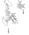
- Fig. 4 shows a state in which the front wheels 20 are pivoted to the right, as seen in the forward direction, until the rear tiller part 38 bears against the right stop 36, even after the stop against the stop 36 there is still a lateral force to the right the drawbar 24 or the front drawbar part 40 is exercised.
- the plates 44 and 46 then pivot against one another, namely tilting or rolling in the process about the contact line formed by the right contact edges 48.
- the right coil springs 56 viewed in the forward direction of travel, hold the plates 44 and 46 together, and the left coil springs 56 are compressed when the drawbar 24, ie its front drawbar part 40, is moved further sideways to the right.
- the relative movement of the rear tiller part 38 to the front Drawbar part 40 is not restricted by the relatively large play between the screws 54 and the bores 59. Therefore, the plates 44 and 46 can tilt or roll relative to each other, and over-steering is absorbed by the spring-loaded connecting mechanism 42.
- the function of the plates 44 and 46 is analogous if there is over-steering to the left, in which case the left contact edges 50 form the contact surfaces. An operator is expected to notice the oversteer condition and stop pivoting the tiller 24 further to one side or the other.
- This invention is not only economical and reliable, but it can also be retrofitted to existing vehicles.
Landscapes
- Engineering & Computer Science (AREA)
- Transportation (AREA)
- Mechanical Engineering (AREA)
- Vehicle Body Suspensions (AREA)
- Agricultural Machines (AREA)
- Springs (AREA)
Applications Claiming Priority (2)
| Application Number | Priority Date | Filing Date | Title |
|---|---|---|---|
| US607034 | 1984-05-04 | ||
| US06/607,034 US4579362A (en) | 1984-05-04 | 1984-05-04 | Laterally yieldable hitch pole for trailing vehicles |
Publications (2)
| Publication Number | Publication Date |
|---|---|
| EP0160893A2 true EP0160893A2 (fr) | 1985-11-13 |
| EP0160893A3 EP0160893A3 (fr) | 1987-09-16 |
Family
ID=24430530
Family Applications (1)
| Application Number | Title | Priority Date | Filing Date |
|---|---|---|---|
| EP85105014A Withdrawn EP0160893A3 (fr) | 1984-05-04 | 1985-04-25 | Dispositif pour joindre une première partie avec une deuxième partie d'un membre tendu |
Country Status (3)
| Country | Link |
|---|---|
| US (1) | US4579362A (fr) |
| EP (1) | EP0160893A3 (fr) |
| CA (1) | CA1242225A (fr) |
Cited By (1)
| Publication number | Priority date | Publication date | Assignee | Title |
|---|---|---|---|---|
| AU669048B2 (en) * | 1993-03-26 | 1996-05-23 | Franz Plasser Bahnbaumaschinen-Industriegesellschaft M.B.H. | A switch transport wagon |
Families Citing this family (10)
| Publication number | Priority date | Publication date | Assignee | Title |
|---|---|---|---|---|
| US5059085A (en) * | 1989-09-14 | 1991-10-22 | Koller Ernest H | Trailer with tiltable bed(s) |
| US5340142A (en) * | 1993-03-10 | 1994-08-23 | E-Z Trail, Inc. | Towing tongue assembly |
| DE19746927C2 (de) * | 1997-10-23 | 1999-09-30 | Horsch Maschinen Gmbh | Landwirtschaftliche Maschine |
| US6158759A (en) * | 1998-11-02 | 2000-12-12 | Perry; Duane L. | Wagon steering control mechanism |
| US6796572B1 (en) * | 2002-05-24 | 2004-09-28 | American Heavy Moving & Rigging Inc. | Method for steering a transport vehicle and apparatus therefor |
| US9072214B2 (en) * | 2009-10-29 | 2015-07-07 | Cnh Industrial America Llc | Steerable agricultural implement with adaptable wheel spacing |
| US9004519B1 (en) * | 2011-09-28 | 2015-04-14 | Geoffrey S. Beech | Tow bar controlled trailer and method |
| CA2772865C (fr) * | 2012-03-30 | 2014-06-10 | Bourgault Industries Ltd. | Dispositif de flottation pour appareils agricoles |
| USD898623S1 (en) * | 2019-04-05 | 2020-10-13 | Ranchwagons L.L.C. | Four wheel towable utility cart |
| US11980125B2 (en) * | 2020-12-18 | 2024-05-14 | Deere & Company | Position detectors for steering systems of agricultural header transport systems |
Family Cites Families (8)
| Publication number | Priority date | Publication date | Assignee | Title |
|---|---|---|---|---|
| US1527469A (en) * | 1923-06-04 | 1925-02-24 | Howard F Clayton | Draft gear for tractors |
| US1610180A (en) * | 1926-04-05 | 1926-12-07 | Byron C Thomson | Cushion drawbar |
| US2923364A (en) * | 1956-03-29 | 1960-02-02 | Case Co J I | Adjustable hitch used for towing implements |
| US3012638A (en) * | 1959-08-05 | 1961-12-12 | Saginaw Products Corp | Cable braked steered running gear assemblies |
| US3340936A (en) * | 1965-04-20 | 1967-09-12 | Byron L Godbersen | Harrow attachment break-away connection |
| US3490544A (en) * | 1966-11-23 | 1970-01-20 | Byron L Godbersen | Harrow attachment breakaway connection with overhead position |
| US3523584A (en) * | 1968-01-29 | 1970-08-11 | Byron L Godbersen | Harrow attachment for roll-over plow |
| FR1575870A (fr) * | 1968-05-16 | 1969-07-25 |
-
1984
- 1984-05-04 US US06/607,034 patent/US4579362A/en not_active Expired - Fee Related
-
1985
- 1985-04-03 CA CA000478258A patent/CA1242225A/fr not_active Expired
- 1985-04-25 EP EP85105014A patent/EP0160893A3/fr not_active Withdrawn
Cited By (1)
| Publication number | Priority date | Publication date | Assignee | Title |
|---|---|---|---|---|
| AU669048B2 (en) * | 1993-03-26 | 1996-05-23 | Franz Plasser Bahnbaumaschinen-Industriegesellschaft M.B.H. | A switch transport wagon |
Also Published As
| Publication number | Publication date |
|---|---|
| US4579362A (en) | 1986-04-01 |
| EP0160893A3 (fr) | 1987-09-16 |
| CA1242225A (fr) | 1988-09-20 |
Similar Documents
| Publication | Publication Date | Title |
|---|---|---|
| DE2134433A1 (de) | An ein Fahrzeug anschließbare Wälzegge | |
| DE69202473T2 (de) | Zugdeichsel für Anhänger. | |
| DE102014009036B4 (de) | Transportfahrzeug, insbesondere selbstangetriebenes Transportfahrzeug, mit variabler Breite | |
| DE19905676B4 (de) | Zugdeichsel für Zentralachsanhänger | |
| DE3316128A1 (de) | Anhaengevorrichtung fuer landwirtschaftliche schlepperfahrzeuge | |
| EP0156985B1 (fr) | Attelage entre véhicule tracteur et remorque, en particulier pour remorque à essieu unique | |
| DE3541203C2 (fr) | ||
| DE2511446A1 (de) | Knickgelenktes fahrzeug | |
| EP0503396B1 (fr) | Machine de fenaison | |
| EP1472922A1 (fr) | Dispositif d'accouplement | |
| DE2658214A1 (de) | Stabilisierungsbaugruppe fuer die geraetetragkonstruktion von zugmaschinen o.dgl. | |
| EP0383013A2 (fr) | Rouleau compacteur | |
| DE2615497C3 (de) | Zugdeichselanordnung für schleppergezogene landwirtschaftliche Maschine | |
| EP0319766A2 (fr) | Dispositif de couplage | |
| EP0556459A1 (fr) | Charrue réversible attelable ou accrochable | |
| DE2440655A1 (de) | Bodenbearbeitungsgeraet fuer schlepperzug mit grosser arbeitsbreite | |
| DE3801895A1 (de) | Vorrichtung an der frontseite eines ackerschleppers zum anheben eines zusatzgewichttraegers in eine transportstellung | |
| DE3032112A1 (de) | Anschlussvorrichtung zum anbringen von landwirtschaftlichen arbeitsmaschinen an einer zugmaschine | |
| DE8501291U1 (de) | Nutzfahrzeug mit hubsattelkupplung zum mitfuehren eines aufliegers | |
| DE3340607A1 (de) | Bodenbearbeitungsgeraet mit grosser arbeitsbreite fuer den anbau an einen schlepper | |
| DE8415686U1 (de) | Bodenbearbeitungsgerät für den Anbau an die Frontseite eines Ackerschleppers | |
| DE69400825T2 (de) | Insbesondere landwirtschaftliches Fahrzeug, umfassend von einem Untergestell getragene Arbeitsorgane und einen Rädersatz, sowie Verbindungsmittel zwischen Untergestell und Rädersatz | |
| EP0538893B1 (fr) | Sellette d'attelage pour véhicule semi-remorque | |
| EP0215349A2 (fr) | Dispositif de levage pour véhicule | |
| DE3913226C2 (fr) |
Legal Events
| Date | Code | Title | Description |
|---|---|---|---|
| PUAI | Public reference made under article 153(3) epc to a published international application that has entered the european phase |
Free format text: ORIGINAL CODE: 0009012 |
|
| AK | Designated contracting states |
Designated state(s): DE FR GB |
|
| 17P | Request for examination filed |
Effective date: 19860509 |
|
| PUAL | Search report despatched |
Free format text: ORIGINAL CODE: 0009013 |
|
| RHK1 | Main classification (correction) |
Ipc: B60D 1/00 |
|
| AK | Designated contracting states |
Kind code of ref document: A3 Designated state(s): DE FR GB |
|
| 17Q | First examination report despatched |
Effective date: 19880804 |
|
| STAA | Information on the status of an ep patent application or granted ep patent |
Free format text: STATUS: THE APPLICATION IS DEEMED TO BE WITHDRAWN |
|
| 18D | Application deemed to be withdrawn |
Effective date: 19901102 |
|
| RIN1 | Information on inventor provided before grant (corrected) |
Inventor name: KIRKPATRICK, KENNETH LAWRENCE |