EP0160986A2 - Handbediente Vorrichtung zum Schleifen eines Ventils - Google Patents
Handbediente Vorrichtung zum Schleifen eines Ventils Download PDFInfo
- Publication number
- EP0160986A2 EP0160986A2 EP85105663A EP85105663A EP0160986A2 EP 0160986 A2 EP0160986 A2 EP 0160986A2 EP 85105663 A EP85105663 A EP 85105663A EP 85105663 A EP85105663 A EP 85105663A EP 0160986 A2 EP0160986 A2 EP 0160986A2
- Authority
- EP
- European Patent Office
- Prior art keywords
- diameter
- cylindrical support
- housing
- small
- bore
- Prior art date
- Legal status (The legal status is an assumption and is not a legal conclusion. Google has not performed a legal analysis and makes no representation as to the accuracy of the status listed.)
- Withdrawn
Links
Images
Classifications
-
- F—MECHANICAL ENGINEERING; LIGHTING; HEATING; WEAPONS; BLASTING
- F01—MACHINES OR ENGINES IN GENERAL; ENGINE PLANTS IN GENERAL; STEAM ENGINES
- F01L—CYCLICALLY OPERATING VALVES FOR MACHINES OR ENGINES
- F01L1/00—Valve-gear or valve arrangements, e.g. lift-valve gear
- F01L1/46—Component parts, details, or accessories, not provided for in preceding subgroups
Definitions
- This invention relates to a tool for resurfacing the annular seating surface on poppet valves as used in internal combustion engines.
- valve refacing device employing a cylindrical housing having a conical recess formed in one or both ends thereof.
- This device employs one or more carbide cutting blades which are positioned within elongated bores formed in the housing and thence project forwardly through elongated slots so that the cutting blades project outwardly from the conical surface.
- the poppet valve is positioned so that the stem projects coaxially through the housing, whereupon the truncated conical seating surface is positioned within the recess for engagement with the cutting blades. Relative rotation between the device and the poppet effects a cutting, and hence a refacing, of the seating surface.
- valve refacing device of Australian Application No. 91999/82 does perform a desirable valve refacing operation, nevertheless this device does possess disadvantages.
- the manner in which the blades are mounted on or within the housing, using either the grooved housing or a separate conical shell increases the complexity of the overall device.
- These arrangements also make it difficult to provide a conical recess having a minimal diameter opening at the apex end of the recess, and hence make it difficult to position the cutting blades close to the small-diameter end of the recess, whereby refacing of very small-diameter poppet valves is difficult, if not impossible.
- a sleevelike housing having an enlarged cylindrical opening which terminates at its inner end in a shoulder.
- a sleevelike cylindrical support is removably positionable within the cylindrical opening and is securable to the housing, as by screws.
- This cylindrical support has a conical recess formed in the outer axial end thereof, which conical recess at its apex end communicates with a small-diameter opening which extends axially through the support and communicates with the opening which extends coaxially of the housing.
- This conical recess is bounded by a conical surface having a plurality of grooves formed therein and projecting radially outwardly thereof.
- the cylindrical support is axially split so as to be defined by a plurality, preferably at least three, of arcuate sectors. This enables the central opening of the cylindrical support to be of minimal diameter, which diameter is, sized (i.e., about 0.5 inch in diameter) so as to normally be only slightly larger than the typical valve stem and is hence a small fraction of the diameter of the conical surface at its outer or large-diameter end, whereby this permits the conical surface to be properly machined so that the apex end communicates with said opening of minimal diameter.
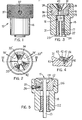
- the inventive valve refinishing tool 10 is specifically for use with a poppet-type valve 11.
- a poppet valve has a truncated conical valve surface 12 formed on the head thereof, which head is secured to one end of an elongated stem 13.
- This valve surface 12 conventionally extends at an angle of either 30° or 45° relative. to a plane which is perpendicular to the longitudinal axis of the valve stem, although other angles are also utilized.
- the tool 10 includes a housing 14 formed substantially as a cylindrical sleeve having an externally stepped configuration.
- This housing 14 has a stepped bore 16 extending coaxially therethrough.
- This bore 16 includes a lower bore 17 which is of smallest diameter, an intermediate bore 18 of intermediate diameter, and an upper bore 19 of largest diameter.
- the lower end of housing 14 has a liner sleeve 21 fixedly positioned within the lower bore 17, such as by being press fit therein.
- This liner sleeve 21 in turn has a sleevelike bushing 22 snugly but removably positioned therein.
- the bushing 22 defines therethrough a bore 23 which is coaxially aligned with the bore 16 so as to snugly accommodate the valve stem 13.
- the sleevelike bushing 22 has a shouldered flange 24 which abuts against the lower axial end of the housing, which shoulder flange enables the bushing 22 to be removed and replaced by a like bushing having a different diameter opening 23 therethrough, whereupon the bushing 23 is selected according to the diameter of the stem13.
- Tool 10 also includes a removable cylindrical support 26 which is positionable within the upper end of the housing 14.
- This cylindrical support 26 includes an inner cylindrical portion 27 which is snugly but removably positioned within the intermediate bore 18, and an outer cylindrical portion 28 which is snugly positioned within the upper bore 19.
- the cylindrical support 26 abuts against a shoulder 29 defined at the interface between the lower and intermediate bores.
- the cylindrical support 26 has a conical bore 31 formed in and opening outwardly through the outer or upper end thereof, which conical bore at its apex or small-diameter end coaxially communicates with a small-diameter cylindrical bore 32 which extends axially downwardly through the cylindrical support 26.
- This bore 31 and its cylindrical opening 32 extends coaxially through the cylindrical support 26 and coaxially communicates with the lower bore portion 17.
- the cylindrical support 26 is axially split so as to define a plurality of arcuate sectors or segments, there being three such segments 33, 33' and 33" in the preferred embodiment. These segments are formed by radial cuts 34 which project inwardly from the periphery of the cylindrical support to the longitudinal axis.
- each of the segments 33, 33', 33" is individually fixedly secured to the housing 14.
- each segment is secured by a pair of screws 37 which are spaced circumferentially and extend through appropriately shouldered openings 36 formed in the housing 14 for threaded engagement with aligned threaded openings formed in the appropriate segment.
- the conical wall 31 has a plurality, here three, of elongated slots or grooves 41 formed therein, there being one said groove 41 formed in each of the segments in the illustrated embodiment.
- These grooves 41 have their inner ends in communication with the opening 32, from which the grooves project radially outwardly along the conical wall 31 so that the outer ends project through the outer or upper axial end of the respective segment.
- An elongated cutting element 42 such as an elongated cutting bar of carbide material having cutting teeth 43 extending in angled relationship across the upper surface thereof, is releasably positioned within each of the grooves 41.
- This cutting element 42 in the illustrated embodiment, has a trapezoidal cross section so that the base width exceeds the top width, and the groove 41 has a similar trapezoidal cross section so that the cutting element 42 hence has to be slidably inserted into the groove from the outer end thereof.
- a small counterbore 44 is formed in the conical surface 31 directly adjacent each of the grooves 41, and an annular wedge 46 is positionable within each counterbore and has an appropriate side surface which wedgingly contacts one of the tapered side surfaces on the respective cutting element 42.
- a screw 47 secures the wedge 46 downwardly to hold the cutting element 42 within its groove.
- the cutting element 41 projects upwardly above the conical surface 31 so as to expose the teeth 43 to permit performance of a refacing operation.
- the three cutting blades 42 are preferably disposed in a nonuniform angularly spaced relationship such that the angles between adjacent blades are not all equal.
- the conical surface 31 associated with the embodiment illustrated by Figure 3 is designed for accommodating a poppet valve having a 45° angle valve seat. This 45° angle is measured relative to a plane which extends perpendicular with respect to the longitudinal axis of the valve stem.
- the support 26 of Figure 3 can be replaced by the modified cylindrical support 126 of Figure 5, which support has a conical surface 131 designed for accommodating a valve seat having an angle of 30°. This modified cylindrical support 126 is otherwise identical to the support 26.
- the tool includes not only the housing 14, but also includes at least two removable cylindrical supports 26 and 126, each of which is preferably defined by three arcuate sectors, with one of the supports being suitable for a 30° valve seat and the other suitable for a 45° valve seat. Further cylindrical supports having different angles thereon can also be provided if desired.
- the cylindrical supports 26 and 126 can hence be readily interchanged depending upon the angle of the valve seat which is to be refaced.
- the segmented construction of the cylindrical support 26 or 126 enables the opening 32 to be of minimal diameter (i.e., about 0.5 inch) and permits the conical surface 31 and grooves 41 to be properly machined so as to extend all the way up to this opening 32.
- This opening 32 is hence only slightly larger than the diameter of the bushing bore 23.
- the blades 42 can thus be positioned so as to readily accommodate valve seats of small diameter.
- a poppet valve is positioned within the tool substantially as illustrated by Figure 5, following which relative rotation effects refinishing of the valve seat 12 due to the latter being rotated across the cutting teeth 43.
- This refacing operation is preferably accomplished manually, such as by securing the free end of the valve stem 13 within a vise so as to stationarily support the valve 11, following which the tool 10 can be manually gripped and axially pulled toward the valve head to control the contact pressure between the cutting blades and the valve seat. Manual rotation of the tool then effects the desired refacing of the valve seat.
Landscapes
- Engineering & Computer Science (AREA)
- Mechanical Engineering (AREA)
- General Engineering & Computer Science (AREA)
- Lift Valve (AREA)
- Turning (AREA)
Applications Claiming Priority (2)
| Application Number | Priority Date | Filing Date | Title |
|---|---|---|---|
| US60806884A | 1984-05-08 | 1984-05-08 | |
| US608068 | 1990-11-01 |
Publications (2)
| Publication Number | Publication Date |
|---|---|
| EP0160986A2 true EP0160986A2 (de) | 1985-11-13 |
| EP0160986A3 EP0160986A3 (de) | 1987-03-04 |
Family
ID=24434890
Family Applications (1)
| Application Number | Title | Priority Date | Filing Date |
|---|---|---|---|
| EP85105663A Withdrawn EP0160986A3 (de) | 1984-05-08 | 1985-05-08 | Handbediente Vorrichtung zum Schleifen eines Ventils |
Country Status (2)
| Country | Link |
|---|---|
| EP (1) | EP0160986A3 (de) |
| AU (1) | AU580057B2 (de) |
Cited By (1)
| Publication number | Priority date | Publication date | Assignee | Title |
|---|---|---|---|---|
| CN119609857A (zh) * | 2024-12-05 | 2025-03-14 | 中船澄西船舶修造有限公司 | 一种割炬针阀修理专用工具 |
Families Citing this family (1)
| Publication number | Priority date | Publication date | Assignee | Title |
|---|---|---|---|---|
| EP0456590B1 (de) * | 1990-05-07 | 1994-04-13 | Serdi - Societe D'etudes De Realisation Et De Diffusion Industrielles | Ventilkopf-Schleifgerät, insbesondere für einen Verbrennungsmotor |
Family Cites Families (6)
| Publication number | Priority date | Publication date | Assignee | Title |
|---|---|---|---|---|
| US1655251A (en) * | 1926-10-29 | 1928-01-03 | Emil O Starkin | Combined valve and valve-seat grinder |
| GB316839A (en) * | 1928-12-10 | 1929-08-08 | George Edward Reibelt | Improvements in facing tools for valves and valve seats |
| GB361345A (en) * | 1929-08-19 | 1931-11-12 | William Stewart Christie | Improvements in and relating to tools for truing valves and valve seats |
| US2588353A (en) * | 1948-11-15 | 1952-03-11 | John V Bueckermann | Valve refinishing tool |
| US3354528A (en) * | 1966-02-21 | 1967-11-28 | Neway Sales Inc | Valve seat cutter |
| AU559340B2 (en) * | 1982-01-06 | 1987-03-05 | Repco Ltd. | Valve face cutting machine |
-
1985
- 1985-05-08 EP EP85105663A patent/EP0160986A3/de not_active Withdrawn
- 1985-05-08 AU AU42084/85A patent/AU580057B2/en not_active Ceased
Cited By (1)
| Publication number | Priority date | Publication date | Assignee | Title |
|---|---|---|---|---|
| CN119609857A (zh) * | 2024-12-05 | 2025-03-14 | 中船澄西船舶修造有限公司 | 一种割炬针阀修理专用工具 |
Also Published As
| Publication number | Publication date |
|---|---|
| EP0160986A3 (de) | 1987-03-04 |
| AU4208485A (en) | 1985-11-14 |
| AU580057B2 (en) | 1988-12-22 |
Similar Documents
| Publication | Publication Date | Title |
|---|---|---|
| US5027684A (en) | Collar for mounting a split saw blade on an arbor | |
| US4637762A (en) | Hand-operated valve refacer | |
| JPS5926411B2 (ja) | 内燃機関のバルブガイド穴とバルブシ−ト面の加工方法ならびにその装置 | |
| US3764204A (en) | Valve guide boring fixture | |
| IL150013A (en) | Rotary cutting tool | |
| US5017062A (en) | Tool for precision machining | |
| US3157068A (en) | Apparatus for reconditioning valve guides | |
| US3674375A (en) | Valve-guide coring tool | |
| EP1403003B1 (de) | Werkzeug von Bestandteilen bei der Fertigung | |
| CN110712127B (zh) | 复合磨削夹具及旋转轴加工方法 | |
| EP0160986A2 (de) | Handbediente Vorrichtung zum Schleifen eines Ventils | |
| US4547997A (en) | Adjustable tool mount | |
| US4106880A (en) | Portable field machine for cutting, grinding and lapping valve seats | |
| US4930948A (en) | Valve seat refitting apparatus | |
| US4204784A (en) | Tools for reconditioning a valve seat in a tap | |
| US5704741A (en) | Valve seat tool | |
| US5791661A (en) | Compliant chuck jaws | |
| US2026821A (en) | Apparatus for renewing worn valve seats | |
| US2106173A (en) | Bibb seating tool | |
| US1667918A (en) | Method and apparatus for reseating valves | |
| US20130183114A1 (en) | Multiple angle valve seat cutter blades and method | |
| US3248975A (en) | Counter-sinking and burr-removing tool | |
| US3391604A (en) | Stabilizing adapter and valve seat depth regulator | |
| US2479660A (en) | Combination cutter and pilot adapter | |
| US2600280A (en) | Circular cutting tool |
Legal Events
| Date | Code | Title | Description |
|---|---|---|---|
| PUAI | Public reference made under article 153(3) epc to a published international application that has entered the european phase |
Free format text: ORIGINAL CODE: 0009012 |
|
| AK | Designated contracting states |
Designated state(s): DE FR GB |
|
| PUAL | Search report despatched |
Free format text: ORIGINAL CODE: 0009013 |
|
| AK | Designated contracting states |
Kind code of ref document: A3 Designated state(s): DE FR GB |
|
| RHK1 | Main classification (correction) |
Ipc: B24B 15/04 |
|
| 17P | Request for examination filed |
Effective date: 19870903 |
|
| 17Q | First examination report despatched |
Effective date: 19881128 |
|
| STAA | Information on the status of an ep patent application or granted ep patent |
Free format text: STATUS: THE APPLICATION IS DEEMED TO BE WITHDRAWN |
|
| 18D | Application deemed to be withdrawn |
Effective date: 19891018 |
|
| RIN1 | Information on inventor provided before grant (corrected) |
Inventor name: ACKER, FRANKLIN L. |