EP0161012B1 - Schusssucheinrichtung für Webstühle - Google Patents
Schusssucheinrichtung für Webstühle Download PDFInfo
- Publication number
- EP0161012B1 EP0161012B1 EP85200300A EP85200300A EP0161012B1 EP 0161012 B1 EP0161012 B1 EP 0161012B1 EP 85200300 A EP85200300 A EP 85200300A EP 85200300 A EP85200300 A EP 85200300A EP 0161012 B1 EP0161012 B1 EP 0161012B1
- Authority
- EP
- European Patent Office
- Prior art keywords
- clutch
- machine
- attached
- shot
- component
- Prior art date
- Legal status (The legal status is an assumption and is not a legal conclusion. Google has not performed a legal analysis and makes no representation as to the accuracy of the status listed.)
- Expired
Links
- 238000009941 weaving Methods 0.000 title claims description 7
- 244000144983 clutch Species 0.000 claims 5
- 238000010276 construction Methods 0.000 description 1
- 238000001514 detection method Methods 0.000 description 1
- 239000004744 fabric Substances 0.000 description 1
Images
Classifications
-
- D—TEXTILES; PAPER
- D03—WEAVING
- D03D—WOVEN FABRICS; METHODS OF WEAVING; LOOMS
- D03D51/00—Driving, starting, or stopping arrangements; Automatic stop motions
- D03D51/06—Driving, starting, or stopping arrangements; Automatic stop motions using particular methods of stopping
- D03D51/08—Driving, starting, or stopping arrangements; Automatic stop motions using particular methods of stopping stopping at definite point in weaving cycle, or moving to such point after stopping
Definitions
- the present invention involves a shot seeking mechanism for weaving looms.
- weaving looms are almost always equipped with a weft stop motion which enables faulty wefts to be detected and the machine to be stopped automatically when such a faulty weft is detected.
- This invention thus involves a shot seeking mechanism, in other words a mechanism by means of which it is possible to carry out the removal of such faulty wefts in a very simple manner and in a minimum of time.
- this mechanism as described by the invention is designed to enable it to be used to run the machine slowly forwards, requiring only one motor to do so.
- a shot seeking mechanism for weaving looms comprising the features of the preamble of claim 1 is disclosed by the patent applications DE-A-2509665 and DE-A-2222151, which however show the disadvantage of a complex construction.
- the present invention relates to a mechanism which does not show the said disadvantage.
- the invention consists in a shot seeking mechanism for weaving looms comprising two clutches, each of which is respectively constituted primarily of two clutch units, wherein one clutch is placed between a drive component and a driven component of the main shaft of the machine, while the second clutch is placed between the driven component of the main shaft of the machine and an auxiliary drive motor characterized by one of the clutch units of each of the respective clutches, being attached to a common support, with respect to which the other clutch units of the respective clutches are capable of being moved independently in order to engage one of the clutches and disengage the other one, or even to engage both clutches; one of the said movable clutch units being attached to a support or disc which is attached to the drive component of the main shaft of the machine; the other movable clutch unit being attached to a support . or disc which may be driven using the auxiliary drive motor; and said common support being attached to the driven component of the main shaft of the machine.
- This type of shot seeking mechanism can be used to drive any type of shed motion, i.e. a cam mechanism, a dobby mechanism a jacquard machine or any other drive system, which, if electromagnetic clutches are used, greatly simplifies the control and automation of the system.
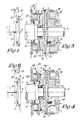
- the shot seeking mechanism as described by the invention consists primarily of two clutches, 1 and 2 respectively, placed between the drive component 3 and the driven component 4 of the main shaft of the machine, whereby the drive component 3 of the main shaft is linked with a first component 5 of clutch 1, while the driven component 4 of the main shaft is linked simultaneously with both the second component 6 of clutch 1 and the first component 7 of clutch 2.
- the second component 8 of clutch 2 is placed so that it can rotate very freely around the aforementioned component 4 of the main shaft and is linked by a gearwheel 9 which is connected in an appropriate manner, for example by means of a chain 10, with a gearwheel 11 which is firmly attached to the shaft 12 of a motor 13.
- Figure 1 shows the position of clutches 1 and 2 during normal operation of the loom.
- the clutch units or parts 5 and 6 of clutch 1 engage with each other and the clutch units or parts 7 and 8 of clutch 2 are disengaged from each other.
- the auxiliary motor 13 is in a position of rest.
- motor 13 is also started, thus enabling the main shaft 4 to be wound back, for example by one full revolution, after which motor 13 is stopped; components 7 and 8 of clutch 2 are once more disengaged and components 5 and 6 are once more engaged with each other.
- Clutches 1 and 2 may be operated by any means whatsoever, although this should preferably be performed by electromagnetic means.
- clutch components 6 and 7 should be capable of being moved independently in order to disengage clutch 1 and engage clutch 2 or vice-versa, or even to engage both clutches.
- a disc 14 is attached onto shaft 3 in such a way that it may rotate freely with respect to an annular disc 15, attached to the machine frame, in which magnets 16 are fitted which, when activated, attract a disc 17 against the resistance of springs 18, for which purpose component 5 of clutch 1 is fitted on disc 17.
- a freely rotating disc 20 is mounted next to disc 19, for example by means of a ball bearing 21 whereby springs 22 attempt to hold component 8 of clutch 2 free from component 7 of this clutch.
- Disc 20 can be moved with respect to disc 19 against the resistance of springs 22 by means of magnets 23 fitted in a disc 24 attached to the machine frame.
- Disc 20 is made up in the form of a gearwheel.
Landscapes
- Engineering & Computer Science (AREA)
- Textile Engineering (AREA)
- Looms (AREA)
Claims (3)
Applications Claiming Priority (2)
| Application Number | Priority Date | Filing Date | Title |
|---|---|---|---|
| BE2060385 | 1984-04-06 | ||
| BE2/60385A BE899346A (nl) | 1984-04-06 | 1984-04-06 | Schotzoekinrichting voor weefgetouwen. |
Publications (2)
| Publication Number | Publication Date |
|---|---|
| EP0161012A1 EP0161012A1 (de) | 1985-11-13 |
| EP0161012B1 true EP0161012B1 (de) | 1988-09-21 |
Family
ID=3865684
Family Applications (1)
| Application Number | Title | Priority Date | Filing Date |
|---|---|---|---|
| EP85200300A Expired EP0161012B1 (de) | 1984-04-06 | 1985-03-01 | Schusssucheinrichtung für Webstühle |
Country Status (4)
| Country | Link |
|---|---|
| US (1) | US4592392A (de) |
| EP (1) | EP0161012B1 (de) |
| BE (1) | BE899346A (de) |
| DE (1) | DE3565133D1 (de) |
Cited By (1)
| Publication number | Priority date | Publication date | Assignee | Title |
|---|---|---|---|---|
| DE10318819A1 (de) * | 2003-04-17 | 2004-11-04 | Picanol N.V. | Webmaschine mit Weblade und Fachbildungsmitteln |
Families Citing this family (17)
| Publication number | Priority date | Publication date | Assignee | Title |
|---|---|---|---|---|
| NL8600870A (nl) * | 1986-04-07 | 1987-11-02 | Picanol Nv | Aandrijving voor weefmachines. |
| DE3874723D1 (en) * | 1987-08-12 | 1992-10-22 | Fred 4400 Muenster De Borisch | Weaving loom with mechanical dobby |
| IT1223621B (it) * | 1987-12-30 | 1990-09-29 | Baruffaldi Spa | Giunto a doppio innesto, particolarmente per telai da tessitura |
| BE1004064A3 (nl) * | 1989-06-29 | 1992-09-15 | Picanol Nv | Weefmachine met vergrendeling. |
| BE1004896A3 (nl) * | 1991-05-23 | 1993-02-16 | Picanol Nv | Werkwijze en inrichting voor het aandrijven van een weefmachine gedurende de traagloop. |
| EP0616062A1 (de) * | 1993-03-17 | 1994-09-21 | Sulzer RàTi Ag | Schussbruchbehebung bei Projektilwebmaschinen |
| BE1009097A3 (nl) * | 1995-02-07 | 1996-11-05 | Picanol Nv | Weefmachine met aandrijving. |
| FR2755155B1 (fr) * | 1996-10-25 | 1998-12-11 | Warner France | Dispositif formant accouplement a deux embrayages en particulier pour un metier a tisser |
| IT1290504B1 (it) * | 1997-03-28 | 1998-12-04 | Baruffaldi Spa | Innesto motorizzato per l'azionamento di alberi condotti di macchine tessili |
| IT1291311B1 (it) * | 1997-05-06 | 1999-01-07 | Baruffaldi Spa | Giunto per l'accoppiamento in rotazione di alberi di azionamento di macchine di armatura e telai di macchine utensili |
| IT1292069B1 (it) * | 1997-06-03 | 1999-01-25 | Vamatex Nuova Spa | Dispositivo di selezione della marcia-lenta e di ricerca del passo in telai di tessitura |
| IT1297940B1 (it) * | 1997-12-23 | 1999-12-20 | Vamatex Nuova Spa | Meccanismo perfezionato di selezione ed innesto della marcia-lenta e di ricerca del passo |
| DE10302506A1 (de) * | 2003-01-23 | 2004-09-02 | Zf Friedrichshafen Ag | Elektromagnetisch betätigbare Doppelkupplungs-Bremskombination |
| DE102004045208A1 (de) * | 2004-09-17 | 2006-04-06 | Siemens Ag | Webmaschine |
| US10501872B2 (en) * | 2015-08-26 | 2019-12-10 | Picanol | Drive mechanism for driving a heald frame of a weaving machine |
| CN108866760B (zh) * | 2018-09-13 | 2020-09-22 | 山东日发纺织机械有限公司 | 剑杆织机自动寻纬装置 |
| CN109274200B (zh) * | 2018-11-05 | 2019-10-25 | 大庆市华禹石油机械制造有限公司 | 一种电动机输出轴连接轴承组件 |
Family Cites Families (9)
| Publication number | Priority date | Publication date | Assignee | Title |
|---|---|---|---|---|
| GB649032A (en) * | 1943-05-12 | 1951-01-17 | Guillaume Diederichs Fils De | Reversing gear for weaving looms |
| US3175665A (en) * | 1962-02-15 | 1965-03-30 | Bendix Corp | Electromagnetic friction clutch |
| AT257293B (de) * | 1965-05-25 | 1967-09-25 | Vyzk Ustav Bavlnarsky | Elektromagnetische Kupplung |
| GB1390377A (en) * | 1971-05-07 | 1975-04-09 | Nuovo Pignone Spa | Looms |
| DE2509665A1 (de) * | 1975-03-06 | 1976-09-09 | Lentz Textilmaschinen Gmbh | Webmaschine mit einer fachbildeeinrichtung, insbesondere schaftmaschine oder jacquardmaschine |
| CH648881A5 (de) * | 1980-10-20 | 1985-04-15 | Staeubli Ag | Schuss-suchvorrichtung mit kriechgang. |
| FR2520762A1 (fr) * | 1982-01-29 | 1983-08-05 | Staubli Sa Ets | Perfectionnements aux dispositifs pour la recherche du pas associes aux ratieres et autres mecaniques de tissage |
| IT1149570B (it) * | 1982-02-09 | 1986-12-03 | Fimtessile | Dispositivo perfezionato per la ricerca del passo delle macchine di armatura in telai di tessitura |
| DE19549084A1 (de) * | 1995-12-29 | 1997-07-03 | Wacker Chemie Gmbh | Pulverförmige, redispergierbare Bindemittel |
-
1984
- 1984-04-06 BE BE2/60385A patent/BE899346A/nl not_active IP Right Cessation
-
1985
- 1985-03-01 DE DE8585200300T patent/DE3565133D1/de not_active Expired
- 1985-03-01 EP EP85200300A patent/EP0161012B1/de not_active Expired
- 1985-03-11 US US06/710,692 patent/US4592392A/en not_active Expired - Fee Related
Cited By (1)
| Publication number | Priority date | Publication date | Assignee | Title |
|---|---|---|---|---|
| DE10318819A1 (de) * | 2003-04-17 | 2004-11-04 | Picanol N.V. | Webmaschine mit Weblade und Fachbildungsmitteln |
Also Published As
| Publication number | Publication date |
|---|---|
| EP0161012A1 (de) | 1985-11-13 |
| DE3565133D1 (en) | 1988-10-27 |
| US4592392A (en) | 1986-06-03 |
| BE899346A (nl) | 1984-10-08 |
Similar Documents
| Publication | Publication Date | Title |
|---|---|---|
| EP0161012B1 (de) | Schusssucheinrichtung für Webstühle | |
| US4875565A (en) | Coupling with two clutches, especially for looms | |
| JP4187280B2 (ja) | 織機の駆動装置 | |
| US4509629A (en) | Plural motor plural clutch with worm drive | |
| EP0675218A1 (de) | Verfahren und Vorrichtung zum Steuern der Fachbildung in einer Webmaschine | |
| EP0514959B1 (de) | Verfahren und Vorrichtung zum Antrieb einer Webmaschine im Langsamlauf | |
| US4657051A (en) | Weaving machine | |
| US7857011B2 (en) | Drive for a web machine | |
| EP0406207A1 (de) | Webmaschine mit Verriegelung | |
| US6009989A (en) | Coupling for rotationally connecting together the drive shafts of weave machines and weaving looms | |
| EP0241076B1 (de) | Transmission für Webmaschinen | |
| EP1191137B1 (de) | Kupplung zum drehfesten Verbinden der Antriebswellen von Schaftmaschinnen und Webmaschinen | |
| EP1245707B1 (de) | Multipositionskupplung mit Blockiereinrichtung des beweglichen Elementes in einer Webmaschinenantriebsvorrichtung | |
| EP1600542A2 (de) | Steuervorrichtung für Webmaschinen | |
| US3828824A (en) | Device for engaging and disengaging the dobby shaft and picking shaft of looms | |
| US3831637A (en) | Device for controlling the heddles of the harness of a loom | |
| EP0086999A1 (de) | Vorrichtung zum Synchronisieren einer Fachbildemaschine mit einer Webmaschinen | |
| EP0869210A1 (de) | Motorisierte Kupplung zum Betrieb von Abtriebswellen bei Webmaschinen | |
| US4036266A (en) | Take-up motion for looms | |
| DE1535525B2 (de) | AnIaBvorrichtung für Webmaschinen | |
| KR860000425A (ko) | 원형직기 구동장치 | |
| JPH0243908Y2 (de) | ||
| US4569374A (en) | Device for stopping the cloth takeup regulator in a weaving loom | |
| EP1096048A2 (de) | Automatische Nadelwebmaschine zur Herstellung von Bänder | |
| US4474220A (en) | Mechanisms for driving regulators in weaving looms |
Legal Events
| Date | Code | Title | Description |
|---|---|---|---|
| PUAI | Public reference made under article 153(3) epc to a published international application that has entered the european phase |
Free format text: ORIGINAL CODE: 0009012 |
|
| AK | Designated contracting states |
Designated state(s): CH DE FR GB IT LI NL |
|
| 17P | Request for examination filed |
Effective date: 19851202 |
|
| RAP1 | Party data changed (applicant data changed or rights of an application transferred) |
Owner name: PICANOL N.V. |
|
| 17Q | First examination report despatched |
Effective date: 19870514 |
|
| GRAA | (expected) grant |
Free format text: ORIGINAL CODE: 0009210 |
|
| AK | Designated contracting states |
Kind code of ref document: B1 Designated state(s): CH DE FR GB IT LI NL |
|
| REF | Corresponds to: |
Ref document number: 3565133 Country of ref document: DE Date of ref document: 19881027 |
|
| ET | Fr: translation filed | ||
| ITF | It: translation for a ep patent filed | ||
| PLBI | Opposition filed |
Free format text: ORIGINAL CODE: 0009260 |
|
| 26 | Opposition filed |
Opponent name: DOTT. ING. PROF. A. RAIMONDI Effective date: 19890602 |
|
| NLR1 | Nl: opposition has been filed with the epo |
Opponent name: DOTT. ING. PROF. A. RAIMONDI |
|
| PGFP | Annual fee paid to national office [announced via postgrant information from national office to epo] |
Ref country code: DE Payment date: 19900518 Year of fee payment: 6 |
|
| PGFP | Annual fee paid to national office [announced via postgrant information from national office to epo] |
Ref country code: FR Payment date: 19910221 Year of fee payment: 7 |
|
| PGFP | Annual fee paid to national office [announced via postgrant information from national office to epo] |
Ref country code: GB Payment date: 19910301 Year of fee payment: 7 |
|
| PGFP | Annual fee paid to national office [announced via postgrant information from national office to epo] |
Ref country code: CH Payment date: 19910320 Year of fee payment: 7 |
|
| ITTA | It: last paid annual fee | ||
| PGFP | Annual fee paid to national office [announced via postgrant information from national office to epo] |
Ref country code: NL Payment date: 19910331 Year of fee payment: 7 |
|
| RDAG | Patent revoked |
Free format text: ORIGINAL CODE: 0009271 |
|
| STAA | Information on the status of an ep patent application or granted ep patent |
Free format text: STATUS: PATENT REVOKED |
|
| 27W | Patent revoked |
Effective date: 19910315 |
|
| GBPR | Gb: patent revoked under art. 102 of the ep convention designating the uk as contracting state | ||
| REG | Reference to a national code |
Ref country code: CH Ref legal event code: PL |
|
| NLR2 | Nl: decision of opposition |