EP0161042A2 - Automatische Nachfüllregelung - Google Patents
Automatische Nachfüllregelung Download PDFInfo
- Publication number
- EP0161042A2 EP0161042A2 EP85301352A EP85301352A EP0161042A2 EP 0161042 A2 EP0161042 A2 EP 0161042A2 EP 85301352 A EP85301352 A EP 85301352A EP 85301352 A EP85301352 A EP 85301352A EP 0161042 A2 EP0161042 A2 EP 0161042A2
- Authority
- EP
- European Patent Office
- Prior art keywords
- tank
- liquid
- probe
- syrup
- low
- Prior art date
- Legal status (The legal status is an assumption and is not a legal conclusion. Google has not performed a legal analysis and makes no representation as to the accuracy of the status listed.)
- Granted
Links
Images


Classifications
-
- G—PHYSICS
- G07—CHECKING-DEVICES
- G07F—COIN-FREED OR LIKE APPARATUS
- G07F13/00—Coin-freed apparatus for controlling dispensing or fluids, semiliquids or granular material from reservoirs
-
- G—PHYSICS
- G01—MEASURING; TESTING
- G01F—MEASURING VOLUME, VOLUME FLOW, MASS FLOW OR LIQUID LEVEL; METERING BY VOLUME
- G01F23/00—Indicating or measuring liquid level or level of fluent solid material, e.g. indicating in terms of volume or indicating by means of an alarm
- G01F23/22—Indicating or measuring liquid level or level of fluent solid material, e.g. indicating in terms of volume or indicating by means of an alarm by measuring physical variables, other than linear dimensions, pressure or weight, dependent on the level to be measured, e.g. by difference of heat transfer of steam or water
- G01F23/24—Indicating or measuring liquid level or level of fluent solid material, e.g. indicating in terms of volume or indicating by means of an alarm by measuring physical variables, other than linear dimensions, pressure or weight, dependent on the level to be measured, e.g. by difference of heat transfer of steam or water by measuring variations of resistance of resistors due to contact with conductor fluid
- G01F23/241—Indicating or measuring liquid level or level of fluent solid material, e.g. indicating in terms of volume or indicating by means of an alarm by measuring physical variables, other than linear dimensions, pressure or weight, dependent on the level to be measured, e.g. by difference of heat transfer of steam or water by measuring variations of resistance of resistors due to contact with conductor fluid for discrete levels
- G01F23/242—Mounting arrangements for electrodes
-
- B—PERFORMING OPERATIONS; TRANSPORTING
- B67—OPENING, CLOSING OR CLEANING BOTTLES, JARS OR SIMILAR CONTAINERS; LIQUID HANDLING
- B67D—DISPENSING, DELIVERING OR TRANSFERRING LIQUIDS, NOT OTHERWISE PROVIDED FOR
- B67D1/00—Apparatus or devices for dispensing beverages on draught
-
- B—PERFORMING OPERATIONS; TRANSPORTING
- B67—OPENING, CLOSING OR CLEANING BOTTLES, JARS OR SIMILAR CONTAINERS; LIQUID HANDLING
- B67D—DISPENSING, DELIVERING OR TRANSFERRING LIQUIDS, NOT OTHERWISE PROVIDED FOR
- B67D1/00—Apparatus or devices for dispensing beverages on draught
- B67D1/0015—Apparatus or devices for dispensing beverages on draught the beverage being prepared by mixing at least two liquid components
- B67D1/0016—Apparatus or devices for dispensing beverages on draught the beverage being prepared by mixing at least two liquid components the beverage being stored in an intermediate container before dispensing, i.e. pre-mix dispensers
-
- B—PERFORMING OPERATIONS; TRANSPORTING
- B67—OPENING, CLOSING OR CLEANING BOTTLES, JARS OR SIMILAR CONTAINERS; LIQUID HANDLING
- B67D—DISPENSING, DELIVERING OR TRANSFERRING LIQUIDS, NOT OTHERWISE PROVIDED FOR
- B67D1/00—Apparatus or devices for dispensing beverages on draught
- B67D1/08—Details
- B67D1/10—Pump mechanism
-
- B—PERFORMING OPERATIONS; TRANSPORTING
- B67—OPENING, CLOSING OR CLEANING BOTTLES, JARS OR SIMILAR CONTAINERS; LIQUID HANDLING
- B67D—DISPENSING, DELIVERING OR TRANSFERRING LIQUIDS, NOT OTHERWISE PROVIDED FOR
- B67D3/00—Apparatus or devices for controlling flow of liquids under gravity from storage containers for dispensing purposes
-
- G—PHYSICS
- G05—CONTROLLING; REGULATING
- G05D—SYSTEMS FOR CONTROLLING OR REGULATING NON-ELECTRIC VARIABLES
- G05D9/00—Level control, e.g. controlling quantity of material stored in vessel
- G05D9/12—Level control, e.g. controlling quantity of material stored in vessel characterised by the use of electric means
-
- B—PERFORMING OPERATIONS; TRANSPORTING
- B67—OPENING, CLOSING OR CLEANING BOTTLES, JARS OR SIMILAR CONTAINERS; LIQUID HANDLING
- B67D—DISPENSING, DELIVERING OR TRANSFERRING LIQUIDS, NOT OTHERWISE PROVIDED FOR
- B67D2210/00—Indexing scheme relating to aspects and details of apparatus or devices for dispensing beverages on draught or for controlling flow of liquids under gravity from storage containers for dispensing purposes
- B67D2210/00146—Component storage means
- B67D2210/00149—Fixed containers to be filled in situ
- B67D2210/00152—Automatically
- B67D2210/00157—Level detected electrically by contact with sensors
Definitions
- the present invention relates very generally to liquid dispensing machines and pertains, more particularly, to automatically controlled apparatus for providing for self-fill of the tank of a dispensing machine. Even more particularly, the invention relates to an automatic self-fill apparatus embodied in control circuit means for use with a machine that dispenses a liquid comprised of water and a concentrate syrup adapted to be jointly fed to a tank of the machine.
- Machines that dispense a beverage are typically comprised of a tank for the storage of a beverage.
- the beverage is typically made up of a mixture of water and a concentrate syrup maintained at a cool temperature by means of evaporation cooling coils.
- These machines may have a water inlet feed but for the most part, the beverage in the storage tank of the dispenser is replenished by means of emptying a container of the syrup concentrate into the tank when the tank is sufficiently low to enable the tank to receive the full amount of concentrate in the concentrate container. Water is then added in an appropriate amount to provide the proper concentration of the beverage. This normal operation of replenishing the beverage in the tank is relatively messy to carry out and is time consuming.
- This prior technique is also a drawback in that the machine is required to be out of operation for a period of time while the replenishment takes place. Also, in replenishing the beverage it is necessary to wait a significant period of time until the entire content of the tank is cooled to serving temperature.
- Another object of the present invention is to provide an automatic self-fill apparatus for a dispensing machine in which the fill operates in an automatic fashion so as to maintain the level of the beverage within a certain range in the tank. This normally maintains the beverage between set upper and lower limits as far as the level of beverage in the tank of the dispensing machine is concerned.
- a further object of the present invention is to provide an automatic self-fill apparatus for a dispensing machine which is safe in operation, is relatively easy to maintain, and which can be incorporatea into the dispensing machine relatively inexpensively.
- Still another object of the present invention is to provide an automatic self-fill apparatus further having the feature of achieving automatic-fill with an adjustable, consistant proportioning of syrup to water and thus provide the desired concentration of the beverage.
- an automatic self-fill apparatus for a machine that dispenses beverages which are generally comprised of water and a concentrate syrup which are adapted to be mixed together within a tank of the dispensing machine.
- the apparatus of the present invention comprises a sensor member disposed in the tank in a position so as to be responsive to the rise and fall of liquid in the tank.
- the sensor member preferably comprises a support post disposed in an upright position in the tank.
- Pump means are provided to pump the syrup to the tank.
- Water control means is also provided such as a water solenoid valve for controlling water flow to the tank.
- the lines that couple to the tank preferably include fill pipes that are adapted to feed the water and syrup concentrate to a top end of the tank.
- the sensor member comprises probes which include a low probe for detecting a low predetermined level of liquid in the tank and a high probe for detecting a high predetermined level of liquid in the tank and adapted to respectively generate low and high probe signals.
- Control circuit means is used responsive to the low and high probe signals for controlling the pump and water fill valve to operate when the low probe is uncovered and terminating pumping action when the liquid level reaches the high probe position, thereby maintaining the liquid level in the tank at a level between the low and high probes at all times.
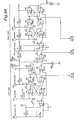
- FIGS. 1A and lB there is depicted in FIGS 1A and lB the control circuitry of the present invention for providing the automatic self-fill in connection with a dispensing machine.
- the dispensing machine with which the concepts of the invention are practiced may be of the general type depicted in FIGS. 2-5 herein, although, the concepts of the invention may also be practiced with many other forms of dispensing machine.
- FIGS. 2-5 herein illustrate the preferred embodiment of the automatic self-fill dispensing machine in accordance with the present invention.
- FIG. 2 illustrates a front perspective view of the twin tank dispensing machine with one of the tanks partially cut away to illustrate the fill pipes and probe assembly.
- FIG. 3 is a cross sectional view taken along line 3-3 showing further details thereof.
- FIG. 4 is a further cross sectional view taken along line 4-4 of FIG. 3 showing further details of the probe assembly.
- FIG. 5 is a rear perspective view of the dispensing machine with the housing cut away.
- FIGS 1A and 1 B show logic control circuitry for providing automatic self-fill in connection with a dispensing machine such as one that dispenses flavored fruit beverages.
- a portion of the control circuitry may be separated into two sections; one associated with a left liquid tank 8 and the other associated with a right liquid tank 9.
- Each of these tanks has associated therewith basically three probes the physical arrangement of which is depicted in FIGS. 2-4.
- a support post 11 illustrated, for example, in FIG. 3, disposed between two fill pipes 13 and 15. These fill pipes are for respectively receiving water and the syrup concentrate.
- probes including a low probe ring 17, a high probe ring 19, and a top probe cap 21 which is for a system override function.
- FIG. 2 shows the dispensing machine with its base B and associated drip tray T upon which a cup can rest under either one of the dispensing nozzles.
- a dispensing nozzle associated with each of the tanks 8 and 9.
- FIG. 1 also illustrates an indicator I and switches SW1 and SW2.
- the indicator I is an out-of-syrup light.
- the switch SW1 is a prime switch to be discussed in detail hereinafter in connection with the circuit diagram.
- the switch SW2 ( switch 52 in FIG . 1B) is a power switch for enabling automatic filling.
- FIG. 3 shows the fill pipes 13 and 15 along with the support post 11 which comprises part of the overall probe assembly.
- FIG. 3 also shows the probe rings 17, 19, and probe cap 21.
- the fill pipes and the support post 11 are all mounted from the evaporator coil housing H.
- the evaporator coils C are shown.
- the three wires at W which couple from the respective probe rings.
- the construction of the evaporator section is well known with the exception that in accordance with the present invention the evaporator housing is also used in a dual manner as a support for the fill pipes and the probe assembly.
- the water fill pipe 13 preferably extends from the evaporator housing at the middle thereof. This is desired so that the evaporator coils C do not interfere with the water fee. If this line is located too close to the evaporator coils C, then freezing of the water may occur.
- FIG. 4 shows the cross sectional details of the probe assembly.
- the majority of the probe assembly is made of an insulating dielectric material with the exception of the probe contacts which are conductive.
- FIG. 4 shows the wiring W individually connecting to the probe contacts such as by being soldered thereto.
- a filler material M may then be used to seal everything together. This may be epoxy.
- FIG. 5 shows further details of the rear of the dispenser which includes a housing 100 for containing and supporting many of the components used in completing the system.
- the line 102 couples from the syrup reservoir associated with the left tank while line 104 couples from the syrup reservoir associated with the right tank.
- the line 102 connects to a left tank syrup sensor 106 while the line 104 couples to a right tank syrup sensor 108.
- the details of the syrup sensor are found in a co-pending application. Basically, each of the probe electrodes 23L and 23R in sensors 106 and 108, respectively, detects the presence of syrup in the respective lines 102 and 104. When the reservoirs are out of syrup then the out-of-syrup sensors give an indication of such which is coupled to the circuitry shown in FIGS. lA and 1B.
- a further line 114 connects from the output of the pump to the left tank to one of the syrup pipes 15L.
- the output of the sensor 108 couples by way of a line 115 to the peristaltic pump 116 associated with the right hand tank.
- a further line not shown in FIG. 5 couples from the output of the pump 116 to the syrup fill tube 15R located in a right hand tank 9.
- a water inlet is also shown in FIG. 5 at water line 120.
- This line splits into lines 122 and 124.
- the line 122 couples to the solenoid valve 128.
- the output of the solenoid valve 128 couples to a water flow control device 130.
- a water adjustment 132 shown in FIG. 2. This is used to adjust the volume of water flow to the output line 134 and the check valve 136. The water then enters the water fill tube 13R and then enters the right tank 9.
- the line 124 couples to the solenoid valve 140.
- the output of the solenoid valve 140 couples to the water flow control device 142 which also has an associated water adjustment on the front panel.
- the output line 144 couples from the output ot the water flow control device 142 to the check valve 146 and from there to the water fill pipe 13L in the left tank.
- a second reason for the above-beverage level inlets for water and syrup is the ease that the Brix or water syrup ratio is checked.
- Brix adjustment is easily made by adjusting the water flow screw, such as the screw 132 shown in FIG. 2, located at the bottom front on each side of the unit. Control via screw 132 controls the water/syrup ratio by permitting more or less water flow during the filling sequence.
- FIG. 5 Also depicted in FIG. 5 are a series of fans Fl and F2 which are used for cooling the pump motor. Also shown are switches SW1 and SW2 along with the indicator I. In addition to the switches and indicators shown in FIGS. 2 and 5, on the opposite or left hand side of the unit there is also an indicator associated with an out-of-syrup sensor associated with the reservoir Rl. There are also a pair of switches on that side including a prime switch associated with the left tank and the reset switch. There is also a water flow adjustment port associated with the left tank in the same position as the adjustment 132 shown in FIG. 2 but on the corresponding side of the dispenser.
- the dispensing unit includes four switches, two on each side, such as depicted by switches SW1 and SW2 in FIG. 2.
- the reset switch comprises a portion of the system override (SOR) circuitry which shuts down the unit if the beverage level rises to the system override probe cap 21.
- the logic in the system override circuit also deactivates the unit after a power failure and of course, when the unit is first plugged in and started. For the moment it is assumed that the system override circuit has been reset and the power supply is energized.
- the circuit diagram also shows the high line 50 coupling to a transformer Tl which has a primary winding P and a secondary winding S.
- the output from the secondary winding couples to a full wave rectifier bridge circuit 65 comprised of diodes D1-D4.
- the output from this circuit couples to filter capacitor C9 and to the zener diode Zl, resistor R7 and transistor Q2.
- a sufficient DC voltage is established at the base of transistor Q2 so as to enable transistor Q2 to be conductive.
- the power supply may be considered as an emitter follower circuit driven by a Zener diode shunt regulator.
- transistor Ql is also conductive; this then provides power to the relay Kl which has a diode D5 coupled there across.
- the circuit diagram also shows a momentary action reset switch 66 and an associated indicator lamp 68. This may be a neon discharge lamp with a series resistor.
- the power neutral at line 70 couples to both the reset switch 66 and the inaicator 68.
- the line 70 also couples to one side of contact KlA associated with relay coil Kl.
- the reset switch 66 is closed provide a path from the neutral line 70 through line 71 to the primary winding P of the transformer Tl. This causes the AC power to be coupled to the rectifier bridge 65 and in turn provides DC power to the transistors Ql and Q2 causing energization of the relay Kl and closure of its associated contact KlA. This latches the power circuit.
- This control circuitry includes gates 12, 14, 16, 18, 20, 22, 24 and a common gate 26. All of these gates are NAND gates.
- the gates 12, 14, 18 and 26 have associated therewith input capacitors C5, C6, C7 and C4, respectively.
- These gates provide for Schmitt triggering hysteresis inherent in the 4093 chip that is used.
- the Schmitt trigger action is provided at the probe input terminals so as to stabilize the logic particularly as the probes gradually dry upon a condition of a receding liquid level.
- the gates 14 and 16 are cross-coupled to form a binary or flip-flop device.
- each of these probe input circuits also includes a resistor such as the respective resistors R8, R9, R10 and R4 each coupling to the negative voltage supply.
- the NAND gates that are used have a logic low output when both inputs are at a logic high and alternatively they have a logic high output when either or both of the inputs are at a logic low level. In connection with the logic that is described herein the gates are connected to the liquid level probes and the probes are grounded by contact with the liquid. In the absence of the conductive liquid, these probes are driven to the negative voltage such as the -13 volts shown by means of the aforementioned resistors.
- the ground level signal corresponds to a logic high or logic "1" and the signal -13 volts corresponds to the logic low or logic "0".
- the ground voltage has been used for logic high to prevent electrolysis corrosion of the probe electrodes by driving them at a negative voltage with respect to the liquid.
- the probes are cathodes which are protected by a cathodic protection principle.
- each of the four liquid sensing probes is ungrounded and the input to each of the corresponding gates 12, 14, 18 and 26 is at its low level (-13 volts).
- the outputs of these gates are thus at their high level or logic "1" (0 volts).
- the high output from gate 14 cross-couples to one input from gate 16 and the output from gate 16 is thus low because both of its inputs are high.
- the high output from gate 14 also couples to gate 20.
- the high output from gate 18 is converted into a low output at the output of gate 22. This, in turn, causes a high output from the gate 20 which in this logic is a ground signal.
- Each side of the dispensing unit has its individual prime switch, such as the switch SW1 shown in FIG. 2. It also has an out-of-syrup light emitting diode or indicator I which glows red when the syrup sensor is empty of syrup, which occurs when the unit is at initial start-up.
- the momentaly contact prime switch such as switch SWl (contacts 53 and 55 or 59 and 61 in FIG. 1B). This starts the pump motor 54 but shuts off the solenoid valve 56 so as not to prefill the bowl with water while the pump is pulling the syrup into the unit.
- the LED I will go out.
- the button is released and the unit will fill both syrup and water.
- the out-of-syrup probe 23L is grounded by the syrup. This causes a low output from gate 18 and a high output from gate 22. This thus causes gate 20 to have two high inputs causing its output to go low or to the voltage level of -13 volts. This energizes the relay coil K3 so as to allow syrup pumping and water flow. Relays K2 and K3 each energize both a water flow solenoid and a peristaltic pump when the prime switch is released.
- an override probe 21L which couples to the corresponding terminal 21L.
- This input couples to the NAND gate 26 and the output or the NAND gate 26 couples to the base of transistor Ql by way of resistor R6.
- the NAND gate 26 functions as an inverter as well as providing Schmitt trigger/driver action.
- the top probe cap 21L is not contacted and thus the output of the gate 26 is high, maintaining the transistor Ql in conduction. However, if due to a malfunction, the probe cap 21L is contacted, then the output of the gate 26 goes low and the transistor Ql ceases conduction. The relay Kl is thus de-energized, removing power from the pump motors, solenoids, and logic circuitry.
- the control circuit also has an input from the out of syrup sensor indicated at terminal 23L and coupling to the NAND gate 18, which also functions as a inverter. As long as there is syrup in the sensor block 106, the output of the gate 18 is low and the output of gate 22 in turn is high. The high output of gate 22 enables gate 20 and thus, as long as the system is not out of syrup, the relay K3 is capable of being energized in a selective manner under control from the output of the bistable device which comprises NAND gates 14 and 16 connected in a cross-coupled manner as illustrated.
- each of the four liquid sensing probes associated with the right tank are ungrounded and thus input to each of the corresponding gates 32, 34, 38 and 26 is at its low level (-13 volts).
- the outputs of these gates are thus at their high level or logic "1" (0 volts).
- the high output from gate 34 cross-couples to one input from gate 36 and the output from gate 36 is thus low because both of its inputs are high.
- the high output from gate 34 also couples to gate 40.
- the high output from gate 38 is converted into a low output at the output of gate 42. This, in turn, causes a high output from the gate 40 which in this logic is a ground signal. This means that the relay K2 is not energized.
- the circuit is in a static state with filling not having yet commenced.
- the out-of-syrup probe 23R is grounded. This causes a low output from gate 38 and a high output from gate 42. This thus causes gate 40 to have two high inputs causing its output to go low or to the voltage level of -13 volts. This energizes the relay K2 so as to allow fluid pumping and fluid flow.
- over-ride probe 21R which couples to the left override probe 21L and hence may be considered an extension of that probe, the function of which has already been discussed.
- the gates identified as gates Ul and U3 are 4093 type NAND gates providing Schmitt trigger action.
- the other gates such as gates U2 and U4 are standard NAND gates which may be of type 4011. The latter gates are not directly connected to the probes.
- the control circuitry depicted herein also includes a high input power line 50 coupled by way of the power switch 52 to both left and right pumps and solenoids.
- a pump motor 54 and associated water solenoid valve 56 see valve 140 in FIG. 5
- a pump motor 58 and associated water solenoid valve 60 see valve 128 in FIG. 5
- the motors 54 and 58 preferably drive peristaltic pumps (see the pumps l12 and 116 in FIG. 2) that are adapted to pump syrup and operate at a speed of 160 RPM.
- the water flow is controlled by a 1.0 GPM flow control device and requires 30-35 PSIG flowing pressure to operate.
- the syrup is contained in a reservoir and flows through a syrup sensor which is the subject matter of a co-pending application serial No. , filed .
- the syrup is drawn past the syrup sensor by the peristaltic pump and from there is discharged into the bowl, above tne beverage level.
- the out-of-syrup circuit allows the apparatus to run when the high resistance but conductive syrup conducts current from its sensor point through the syrup to ground.
- the sensor tip extends into the syrup flow and conducts current.
- the syrup reservoir is empty, the syrup level drops in the sensor housing and the tip is no longer contacted by the syrup. It then no longer conducts and the logic controlling the system shuts down the apparatus.
- the solenoid valves are adapted to deliver about two gallons per minute of water when both sides are filling. They use a 3/8ths inch OD copper line to connect to the machine.
- the water flow comes in from a main pipe and divides flowing through copper lines to the solenoid valves 56 and 60. From there the water flows through a flow control valve with its needle valve adjustment. From the water valve the water flows through a check valve and then through stainless steel tubing into the bowl or tank. Again, like the syrup line, the water line discharges water into the beverage bowl above the liquid level.
- the line 15 may be for syrup and the line 13 for water.
- the fill pipes 13 and 15 are disposed so that they extend above the probe assembly. This is clearly illustrated in FIG. 1 and even more so in FIG. 3. This prevents a back siphoning of beverage into the water line in case of a vacuum in the water line.
Landscapes
- Physics & Mathematics (AREA)
- General Physics & Mathematics (AREA)
- Engineering & Computer Science (AREA)
- Mechanical Engineering (AREA)
- Thermal Sciences (AREA)
- Fluid Mechanics (AREA)
- Automation & Control Theory (AREA)
- Beverage Vending Machines With Cups, And Gas Or Electricity Vending Machines (AREA)
- Superconductors And Manufacturing Methods Therefor (AREA)
- Laying Of Electric Cables Or Lines Outside (AREA)
- Signal Processing For Digital Recording And Reproducing (AREA)
- Elimination Of Static Electricity (AREA)
- Control Of Vehicles With Linear Motors And Vehicles That Are Magnetically Levitated (AREA)
- Charge And Discharge Circuits For Batteries Or The Like (AREA)
- Devices For Dispensing Beverages (AREA)
- Feeding, Discharge, Calcimining, Fusing, And Gas-Generation Devices (AREA)
- Control Of Vending Devices And Auxiliary Devices For Vending Devices (AREA)
- Nonmetallic Welding Materials (AREA)
- Container Filling Or Packaging Operations (AREA)
- Basic Packing Technique (AREA)
Priority Applications (1)
| Application Number | Priority Date | Filing Date | Title |
|---|---|---|---|
| AT85301352T ATE42943T1 (de) | 1984-03-19 | 1985-02-28 | Automatische nachfuellregelung. |
Applications Claiming Priority (2)
| Application Number | Priority Date | Filing Date | Title |
|---|---|---|---|
| US59099284A | 1984-03-19 | 1984-03-19 | |
| US590992 | 1984-03-19 |
Publications (3)
| Publication Number | Publication Date |
|---|---|
| EP0161042A2 true EP0161042A2 (de) | 1985-11-13 |
| EP0161042A3 EP0161042A3 (en) | 1986-03-05 |
| EP0161042B1 EP0161042B1 (de) | 1989-05-10 |
Family
ID=24364583
Family Applications (1)
| Application Number | Title | Priority Date | Filing Date |
|---|---|---|---|
| EP85301352A Expired EP0161042B1 (de) | 1984-03-19 | 1985-02-28 | Automatische Nachfüllregelung |
Country Status (8)
| Country | Link |
|---|---|
| EP (1) | EP0161042B1 (de) |
| JP (1) | JPS60217984A (de) |
| KR (1) | KR900000807B1 (de) |
| AT (1) | ATE42943T1 (de) |
| AU (1) | AU588797B2 (de) |
| BR (1) | BR8501152A (de) |
| CA (1) | CA1244907A (de) |
| DE (1) | DE3570071D1 (de) |
Cited By (15)
| Publication number | Priority date | Publication date | Assignee | Title |
|---|---|---|---|---|
| ES2129374A1 (es) * | 1997-11-10 | 1999-06-01 | Univ Cadiz | Procedimiento automatizado para el estudio de procesos de interaccion solido-agua y un aparato para su realizacion. |
| DE19842484A1 (de) * | 1998-09-16 | 1999-12-02 | Siemens Ag | Verwendung einer Zufuhr- und/oder Entnahmeleitung und Vorratsbehälter mit einer Zufuhr- und/oder Entnahmeleitung |
| EP0952348A3 (de) * | 1998-04-20 | 2000-08-23 | Avcheck Corporation | Automatisches unterirdisches Pumpsystem |
| GB2371539A (en) * | 2001-01-09 | 2002-07-31 | Gary Reece Walton | Portable valve mechanism for filling a container |
| US10087065B2 (en) | 2016-10-11 | 2018-10-02 | Fuel Automation Station, LLC | Mobile distribution station having sensor communication lines routed with hoses |
| US10150662B1 (en) | 2017-10-27 | 2018-12-11 | Fuel Automation Station, Llc. | Mobile distribution station with additive injector |
| US10196258B2 (en) | 2016-10-11 | 2019-02-05 | Fuel Automation Station, LLC | Method and system for mobile distribution station |
| US10289126B2 (en) | 2016-10-11 | 2019-05-14 | Fuel Automation Station, LLC | Mobile distribution station with guided wave radar fuel level sensors |
| US10494251B2 (en) | 2016-10-11 | 2019-12-03 | Fuel Automation Station, LLC | Mobile distribution station with aisle walkway |
| US10513426B2 (en) | 2016-10-11 | 2019-12-24 | Fuel Automation Station, LLC | Mobile distribution station with fail-safes |
| US10633243B2 (en) | 2017-02-24 | 2020-04-28 | Fuel Automation Station, Llc. | Mobile distribution station |
| US10830031B2 (en) | 2018-08-24 | 2020-11-10 | Fuel Automation Station, Llc. | Mobile distribution station having satellite dish |
| US10926996B2 (en) | 2018-05-04 | 2021-02-23 | Fuel Automation Station, Llc. | Mobile distribution station having adjustable feed network |
| US11142449B2 (en) | 2020-01-02 | 2021-10-12 | Fuel Automation Station, LLC | Method and system for dispensing fuel using side-diverting fuel outlets |
| US11827421B2 (en) | 2020-01-17 | 2023-11-28 | Fuel Automation Station, LLC | Fuel cap assembly with cylindrical coupler |
Families Citing this family (5)
| Publication number | Priority date | Publication date | Assignee | Title |
|---|---|---|---|---|
| US5490614A (en) * | 1993-11-10 | 1996-02-13 | Jet Spray Corp. | Beverage dispenser tray assembly |
| US5537838A (en) * | 1994-11-02 | 1996-07-23 | Jet Spray Corp. | Beverage dispenser |
| USD367989S (en) | 1994-11-08 | 1996-03-19 | Jet Spray Corp. | Beverage dispenser |
| USD367586S (en) | 1994-11-08 | 1996-03-05 | Jet Spray Corp. | Bowl for a beverage dispenser |
| US5535600A (en) * | 1994-12-07 | 1996-07-16 | Jet Spray Corp. | Cooling system for a post-mix beverage dispenser |
Family Cites Families (7)
| Publication number | Priority date | Publication date | Assignee | Title |
|---|---|---|---|---|
| US3225965A (en) * | 1961-10-05 | 1965-12-28 | Product R & D Inc | Apparatus for dispensing beverages |
| US3528587A (en) * | 1968-06-25 | 1970-09-15 | Nedlog Co | Automatic liquid feed device |
| JPS5342639U (de) * | 1976-09-16 | 1978-04-12 | ||
| JPS54104050A (en) * | 1978-02-01 | 1979-08-15 | Rei Tech Inc | Electric heating furnace |
| DE2835413A1 (de) * | 1978-08-12 | 1980-02-21 | Hoechst Ag | Einrichtung zur elektrischen standueberwachung einer entwicklerloesung in einem vorratsgefaess |
| JPS5664996A (en) * | 1979-10-31 | 1981-06-02 | Sanyo Jido Hanbaiki Kk | Liquid feeder |
| US4390793A (en) * | 1981-02-23 | 1983-06-28 | International Telephone And Telegraph Corporation | Electronic liquid level control apparatus |
-
1985
- 1985-02-28 EP EP85301352A patent/EP0161042B1/de not_active Expired
- 1985-02-28 DE DE8585301352T patent/DE3570071D1/de not_active Expired
- 1985-02-28 AT AT85301352T patent/ATE42943T1/de not_active IP Right Cessation
- 1985-03-04 AU AU39454/85A patent/AU588797B2/en not_active Ceased
- 1985-03-14 BR BR8501152A patent/BR8501152A/pt unknown
- 1985-03-18 KR KR1019850001744A patent/KR900000807B1/ko not_active Expired
- 1985-03-19 CA CA000476892A patent/CA1244907A/en not_active Expired
- 1985-03-19 JP JP60055638A patent/JPS60217984A/ja active Pending
Cited By (24)
| Publication number | Priority date | Publication date | Assignee | Title |
|---|---|---|---|---|
| ES2129374A1 (es) * | 1997-11-10 | 1999-06-01 | Univ Cadiz | Procedimiento automatizado para el estudio de procesos de interaccion solido-agua y un aparato para su realizacion. |
| EP0952348A3 (de) * | 1998-04-20 | 2000-08-23 | Avcheck Corporation | Automatisches unterirdisches Pumpsystem |
| DE19842484A1 (de) * | 1998-09-16 | 1999-12-02 | Siemens Ag | Verwendung einer Zufuhr- und/oder Entnahmeleitung und Vorratsbehälter mit einer Zufuhr- und/oder Entnahmeleitung |
| GB2371539A (en) * | 2001-01-09 | 2002-07-31 | Gary Reece Walton | Portable valve mechanism for filling a container |
| GB2371539B (en) * | 2001-01-09 | 2003-07-23 | Gary Reece Walton | A portable valve mechanism |
| US10289126B2 (en) | 2016-10-11 | 2019-05-14 | Fuel Automation Station, LLC | Mobile distribution station with guided wave radar fuel level sensors |
| US10087065B2 (en) | 2016-10-11 | 2018-10-02 | Fuel Automation Station, LLC | Mobile distribution station having sensor communication lines routed with hoses |
| US10196258B2 (en) | 2016-10-11 | 2019-02-05 | Fuel Automation Station, LLC | Method and system for mobile distribution station |
| US11261079B2 (en) | 2016-10-11 | 2022-03-01 | Fuel Automation Station, LLC | Mobile distribution station with fail-safes |
| US10303190B2 (en) | 2016-10-11 | 2019-05-28 | Fuel Automation Station, LLC | Mobile distribution station with guided wave radar fuel level sensors |
| US10494251B2 (en) | 2016-10-11 | 2019-12-03 | Fuel Automation Station, LLC | Mobile distribution station with aisle walkway |
| US10513426B2 (en) | 2016-10-11 | 2019-12-24 | Fuel Automation Station, LLC | Mobile distribution station with fail-safes |
| US10705547B2 (en) | 2016-10-11 | 2020-07-07 | Fuel Automation Station, LLC | Mobile distribution station with guided wave radar fuel level sensors |
| US10815118B2 (en) | 2016-10-11 | 2020-10-27 | Fuel Automation Station, LLC | Mobile distribution station having sensor communication lines routed with hoses |
| US12583735B2 (en) | 2016-10-11 | 2026-03-24 | Fuel Automation Station, LLC | Mobile distribution station with fail-safes |
| US12091307B2 (en) | 2016-10-11 | 2024-09-17 | Fuel Automation Station, LLC | Mobile distribution station with fail-safes |
| US10974955B2 (en) | 2016-10-11 | 2021-04-13 | Fuel Automation Station, LLC | Mobile distribution station for fluid dispensing |
| US10633243B2 (en) | 2017-02-24 | 2020-04-28 | Fuel Automation Station, Llc. | Mobile distribution station |
| US10150662B1 (en) | 2017-10-27 | 2018-12-11 | Fuel Automation Station, Llc. | Mobile distribution station with additive injector |
| US10926996B2 (en) | 2018-05-04 | 2021-02-23 | Fuel Automation Station, Llc. | Mobile distribution station having adjustable feed network |
| US10830031B2 (en) | 2018-08-24 | 2020-11-10 | Fuel Automation Station, Llc. | Mobile distribution station having satellite dish |
| US11142449B2 (en) | 2020-01-02 | 2021-10-12 | Fuel Automation Station, LLC | Method and system for dispensing fuel using side-diverting fuel outlets |
| US11827421B2 (en) | 2020-01-17 | 2023-11-28 | Fuel Automation Station, LLC | Fuel cap assembly with cylindrical coupler |
| US12325558B2 (en) | 2020-01-17 | 2025-06-10 | Fuel Automation Station, LLC | Fuel cap assembly with cylindrical coupler |
Also Published As
| Publication number | Publication date |
|---|---|
| BR8501152A (pt) | 1985-11-12 |
| JPS60217984A (ja) | 1985-10-31 |
| EP0161042A3 (en) | 1986-03-05 |
| KR900000807B1 (ko) | 1990-02-17 |
| AU3945485A (en) | 1985-09-26 |
| EP0161042B1 (de) | 1989-05-10 |
| CA1244907A (en) | 1988-11-15 |
| KR850006754A (ko) | 1985-10-16 |
| ATE42943T1 (de) | 1989-05-15 |
| DE3570071D1 (en) | 1989-06-15 |
| AU588797B2 (en) | 1989-09-28 |
Similar Documents
| Publication | Publication Date | Title |
|---|---|---|
| US4728005A (en) | Self-fill system | |
| EP0161042B1 (de) | Automatische Nachfüllregelung | |
| US4632275A (en) | Palatability stabilizer | |
| US4645095A (en) | Syrup sensor for dispensing machine | |
| US4795061A (en) | Apparatus for providing water and syrup in a predetermined ratio to a beverage dispenser | |
| US5190189A (en) | Low height beverage dispensing apparatus | |
| US5842603A (en) | Postmix juice dispenser | |
| US3552726A (en) | Motorless carbonator and method of operation | |
| US4544084A (en) | Beverage dispenser | |
| US4957220A (en) | Vending machine last drink sensor and dispensing apparatus | |
| US4852621A (en) | Bottled water pressurization system | |
| US3400551A (en) | Slush beverage machine | |
| US4717045A (en) | Syrup sensor for dispensing machine | |
| US3528587A (en) | Automatic liquid feed device | |
| US3206069A (en) | Apparatus and method for carbonating and dispensing beverages | |
| JPH02258595A (ja) | 飲料分配弁及び分配方法 | |
| US3643835A (en) | Automatic liquid proportioner | |
| US3369376A (en) | Melt water disposal system for cold drink vendor with ice maker | |
| US4226267A (en) | Vending machine with self contained water supply | |
| KR910000037B1 (ko) | 액체충전용 개폐장치 | |
| US3398550A (en) | Liquid supply control system for a beverage dispenser | |
| US3653640A (en) | Apparatus for preparing and dispensing a mixture of at least two liquids | |
| US5316180A (en) | Beverage dispensing machine with pressurized water and syrup supplies | |
| JP2936107B2 (ja) | 箱収納高粘度飲料バッグ用ポストミックス飲料ディスペンサー装置 | |
| EP1356742B1 (de) | Ausrüstung zur Herstellung und Ausgabe von Eis-Wassermischungen oder gekühlten Getränken |
Legal Events
| Date | Code | Title | Description |
|---|---|---|---|
| PUAI | Public reference made under article 153(3) epc to a published international application that has entered the european phase |
Free format text: ORIGINAL CODE: 0009012 |
|
| AK | Designated contracting states |
Designated state(s): AT BE CH DE FR GB IT LI LU NL SE |
|
| PUAL | Search report despatched |
Free format text: ORIGINAL CODE: 0009013 |
|
| AK | Designated contracting states |
Kind code of ref document: A3 Designated state(s): AT BE CH DE FR GB IT LI LU NL SE |
|
| 17P | Request for examination filed |
Effective date: 19860730 |
|
| 17Q | First examination report despatched |
Effective date: 19870630 |
|
| GRAA | (expected) grant |
Free format text: ORIGINAL CODE: 0009210 |
|
| AK | Designated contracting states |
Kind code of ref document: B1 Designated state(s): AT BE CH DE FR GB IT LI LU NL SE |
|
| PG25 | Lapsed in a contracting state [announced via postgrant information from national office to epo] |
Ref country code: SE Effective date: 19890510 Ref country code: NL Effective date: 19890510 Ref country code: LI Effective date: 19890510 Ref country code: CH Effective date: 19890510 Ref country code: BE Effective date: 19890510 Ref country code: AT Effective date: 19890510 |
|
| REF | Corresponds to: |
Ref document number: 42943 Country of ref document: AT Date of ref document: 19890515 Kind code of ref document: T |
|
| REF | Corresponds to: |
Ref document number: 3570071 Country of ref document: DE Date of ref document: 19890615 |
|
| ITF | It: translation for a ep patent filed | ||
| ET | Fr: translation filed | ||
| REG | Reference to a national code |
Ref country code: CH Ref legal event code: PL |
|
| NLV1 | Nl: lapsed or annulled due to failure to fulfill the requirements of art. 29p and 29m of the patents act | ||
| PG25 | Lapsed in a contracting state [announced via postgrant information from national office to epo] |
Ref country code: LU Free format text: LAPSE BECAUSE OF NON-PAYMENT OF DUE FEES Effective date: 19900228 Ref country code: GB Effective date: 19900228 |
|
| PLBE | No opposition filed within time limit |
Free format text: ORIGINAL CODE: 0009261 |
|
| STAA | Information on the status of an ep patent application or granted ep patent |
Free format text: STATUS: NO OPPOSITION FILED WITHIN TIME LIMIT |
|
| 26N | No opposition filed | ||
| GBPC | Gb: european patent ceased through non-payment of renewal fee | ||
| PG25 | Lapsed in a contracting state [announced via postgrant information from national office to epo] |
Ref country code: FR Effective date: 19901031 |
|
| PG25 | Lapsed in a contracting state [announced via postgrant information from national office to epo] |
Ref country code: DE Effective date: 19901101 |
|
| REG | Reference to a national code |
Ref country code: FR Ref legal event code: ST |