EP0161103A2 - Pont de pesage - Google Patents
Pont de pesage Download PDFInfo
- Publication number
- EP0161103A2 EP0161103A2 EP85303149A EP85303149A EP0161103A2 EP 0161103 A2 EP0161103 A2 EP 0161103A2 EP 85303149 A EP85303149 A EP 85303149A EP 85303149 A EP85303149 A EP 85303149A EP 0161103 A2 EP0161103 A2 EP 0161103A2
- Authority
- EP
- European Patent Office
- Prior art keywords
- platform
- load cell
- weighbridge
- shear beam
- underside
- Prior art date
- Legal status (The legal status is an assumption and is not a legal conclusion. Google has not performed a legal analysis and makes no representation as to the accuracy of the status listed.)
- Withdrawn
Links
- 230000000712 assembly Effects 0.000 claims abstract description 15
- 238000000429 assembly Methods 0.000 claims abstract description 15
- 239000000725 suspension Substances 0.000 claims abstract description 5
- 239000000872 buffer Substances 0.000 description 8
- 238000011068 loading method Methods 0.000 description 5
- 239000000837 restrainer Substances 0.000 description 4
- 239000002184 metal Substances 0.000 description 3
- 238000007747 plating Methods 0.000 description 3
- 230000004224 protection Effects 0.000 description 3
- 230000006835 compression Effects 0.000 description 2
- 238000007906 compression Methods 0.000 description 2
- 238000011065 in-situ storage Methods 0.000 description 2
- 239000000463 material Substances 0.000 description 2
- 230000000452 restraining effect Effects 0.000 description 2
- 230000035939 shock Effects 0.000 description 2
- 229910000760 Hardened steel Inorganic materials 0.000 description 1
- 235000010627 Phaseolus vulgaris Nutrition 0.000 description 1
- 244000046052 Phaseolus vulgaris Species 0.000 description 1
- 229910000831 Steel Inorganic materials 0.000 description 1
- 230000001066 destructive effect Effects 0.000 description 1
- 230000000694 effects Effects 0.000 description 1
- 230000005484 gravity Effects 0.000 description 1
- 238000000034 method Methods 0.000 description 1
- 239000004033 plastic Substances 0.000 description 1
- 229920003023 plastic Polymers 0.000 description 1
- 239000011435 rock Substances 0.000 description 1
- 239000007787 solid Substances 0.000 description 1
- 239000010959 steel Substances 0.000 description 1
Images


Classifications
-
- G—PHYSICS
- G01—MEASURING; TESTING
- G01G—WEIGHING
- G01G19/00—Weighing apparatus or methods adapted for special purposes not provided for in the preceding groups
- G01G19/02—Weighing apparatus or methods adapted for special purposes not provided for in the preceding groups for weighing wheeled or rolling bodies, e.g. vehicles
- G01G19/021—Weighing apparatus or methods adapted for special purposes not provided for in the preceding groups for weighing wheeled or rolling bodies, e.g. vehicles having electrical weight-sensitive devices
-
- G—PHYSICS
- G01—MEASURING; TESTING
- G01G—WEIGHING
- G01G21/00—Details of weighing apparatus
- G01G21/23—Support or suspension of weighing platforms
Definitions
- This invention relates to weighbridges.
- Weighbridge technology normally involves supporting a platform on upstanding canister type compression cells located in mountings secured to a prepared foundation of length and width similar to the platform. At least four cells are required; generally pairs of cells are spaced at longitudinal intervals of about 6 to 8 metres.
- the platform requires to be restrained from undesired horizontal movement when a load is moving onto or leaving the platform, and in addition the cells require protection from platform movement both horizontally (dynamic loading) and vertically (shock loading).
- platforms are mounted on restraining posts which have first to be grouted into the foundation and bushes of tufnol or like hard wearing plastics material are provided to receive the posts.
- the known technology therefore employs equipment or practices which are expensive or time consuming and add to the overall cost of the weighbridge.
- load cells be protected from damage; canister-type compression cells are particularly susceptible to side loadings and as a result preventative mountings for these load cells have been developed to protect them; all of which adds to the cost of the structure and ancillary components.
- the restraining posts arrangement aforementioned has an additional disadvantage in that temperature changes which may be up to 500C can cause the steel platform structure to expand or contract about the fixed post with a resultant inaccuracy in the load cell performance and readings.
- Shear beam load cells are also known from U.K. Patent 1 555 934, these are supported by columns at their ends and have a central depression from which hangs a link twisted through 90° and the link supports the platform which is thus suspended from the centre of each shear bean. At least four such cells are positioned one adjacent to or below each corner of the platform.
- a disadvantage of such load cell assemblies is that horizontal movement of the platform can still occur and restrainers have to be provided.
- a further disadvantage is that the assembly is of such a height, about 4 metre that it has to be located at the side of the platform unless the platform is mounted over a pit.
- An object of this invention is to obviate or mitigate the aforementioned disadvantage.
- a weighbridge comprising a platform supported by a plurality of shear beam load cell assemblies via suspension link means suspended from each assembly and engaging projections on the underside of the platform, characterised in that the shear beam of each load cell assembly has an elongate body supported centrally below the platform and carrying at its ends parallel suspension links the lower ends of which engage projections mounted on the underside of the platform.
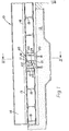
- the weighbridge comprises an elongate rectangular platform 10 suspended from four shear beam load cell assemblies 11 located below the platform adjacent to the sides thereof and spaced a relatively short distance from the ends of the platform, each load cell having a double ended shear beam and being fixedly mounted on a prepared foundation 12.
- the load cell assemblies can be disposed longitudinally, but it has been founu that an even more efficient result is obtained by locating the load cell assemblies transversely as illustrated in Figs. 1 and 2.
- the platform 10 comprises a deck 13 and an under- frame formed by two main longitudinal side beams 14 of T section and series of transverse I beams (transverse) 15 between the side beams 14.
- the lower flanges 15A of the transverse I beams 15 are welded to the inner flanges 14A of the longitudinal side beams 14.
- a box shaped bracket 40 is located below the deck between two transverse I beams 15 as more fully described hereinafter.
- the platform may have a length of up to 18 metres.
- the longitudinal side beams 14 provide the main strength for the platform structure and extend above the height of the platform to additionally provide retaining walls along each side of the deck 13.
- the deck is supported on the upper flanges 15B of the transverse beams and a gap formed between the end of the transverse beams 15 and the spine of the longitudinal beam 14 is covered by a plate 16 of angle section bolted to the longitudinal beam 14.
- the angle plate is at a height such that the extreme edges of the decking locate below it and there is sufficient space between the decking and the angle plate to allow for drainage from the decking in wet weather.
- the foundation 12 comprises two transverse strips of concrete, longitudinally spaced so that one will be located below each end of the platform.
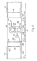
- Each load cell assembly 11 comprises a base plate 20 mounting a plinth 21 which has a semi-cylindrical protrusion 22 across its upper face and a pin 23 extending upwardly from the centre of the protrusion, and a double ended shear beam load cell 24 having a central aperture 25 to loosely receive the pin 23 and a semi-cylindrical depression 26 in its lower face to accommodate the protrusion 22 of the plinth 21 when, the shear beam 24 locates over the pin 23.
- the radius of the depression 26 in the beam 24 is slightly greater than that of the protrusion 22, on the plinth 21 and the diameter of the aperture 25 in the beam 24 is greater than that of the pin 23 so that the beam has a limited pivotal movement on its longitudinal axis, i.e. it can rock slightly on the plinth. The same effect may be obtained with a protrusion on the shear beam and depression in the plinth.
- the shear beam 24 is made of hardened steel and has an elongate body which is square in cross section and rectangular in longitudinal section, said body having a hollow central portion which houses four strain gauges (not shown) hermetically sealed therein and an electrical connection 27 extends from one side of the beam, (the inner side) when the beam is transversely disposed in situ.
- Each end 28 of the beam 24 is capstan-shaped and a metal looped link 29 depends from the recessed portion of each end.
- the lower end of each link engages a capstan-shaped bollard 30 which is mounted on the platform as hereinafter described to suspend the platform from these links.
- the load cells 24 are double- ended, end-loaded centre-mounted shear beam cells, and only four are required for platforms up to 18 metres in length.
- the plinth 21 has a buffer 31 extending from one face, to lie transverse and outwardly facing when the plinth is in situ, and also a buffer 32 extending longitudinally (outwardly) for the purpose hereinafter disclosed. These buffers 31, 32 are length adjustable.
- Each bracket 40 is formed by vertical plating welded between a pair of transverse beams near to each end of the platform, namely transverse plating 41, 42 which extends the full length of the transverse beams to give added strength to the structure, and relatively thick longitudinal plates 43, 44 located inwardly of the longitudinal side beam between the plating 41, 42 and spaced apart to form an enclosed area of substantially square section in plan.
- Co-axial holes are provided in the longitudinal walls 43, 44 to receive the capstan shaped bollards 30.
- These bollards have threaded shanks 46 onto which nuts 47 are located to secure the bollards on the bracket 40. The outer of these bollards can abut the buffer 31 in the plinth 21.
- a solid metal block 48 is mounted on one transverse wall, the one nearest the end of the platform, i.e. wall 41, and it can abut the buffer 32 on the plinth.
- the assemblies 11 lie in the space within the respective box bracket 40.
- a load cell assembly 11 is mounted on each foundation strip and its base plate 20 bolted thereto by bolts 35 (Fig. 5).
- brackets 40 are welded to the underside of the platform deck, and as can be seen from Figs. 1 and 2, these brackets 40 and consequently the load cell assemblies 11 are spaced a relatively short distance from the end of the platform and inwardly of the longitudinal beams 14.
- the deck 13 is formed by a series of transverse plates and at least those over the brackets are removable for access to the load cells.
- the platform 10 is lowered by a crane to overlie the load cells.
- the buffer 31 on the plinth is in line with one of the bollards 30 of the platform underframe and is intended to reduce any small transverse movement of the platform to a minimum when a load is moving onto or leaving the deck.
- the longitudinal buffer 32 is adjacent to a plate and is intended to reduce any small longitudinal movement of the platform.
- the platform is raised a short distance and the metal links 29 positioned on the ends of the shear beams 21 with their lower ends under the bollards 30. Finally the platform is lowered until the bollards 30 sit on the links 29 at which time the weight of the platform is borne by the load cells via their pairs of links.
- the maximum height of the load cell assembly above the foundation 12 is 260 mm (10") and the height of the platform is less than 300 mm, i.e. under 12".
- the plinth 21 on its base 20 extends to a height of 155 mm and the protrusion 22 has a 10 mm radius.
- the load cell double ended shear beam is 76 mm high and the links are 198 mm in length and 24 mm thick, giving an__ inside length of 150 mm.
- a great advantage of a weighbridge having load cell assemblies as hereinbefore described is that the assemblies are small enough in height to be located below the platform even when surface mounted, as opposed to pit-mounted.
- a weighbridge as hereinbefore described is a radical development of all known types of weighbridge structures, eliminating the need for restrainers, anchors, struts, posts, flextures, ball protections and means for protecting the load cells. This is due to the two parallel links on each load cell supporting the platform below the level of the centre of gravity of the load cell assemblies, thus virtually eliminating the destructive forces, i.e. shock loading and dynamic loading which can affect known load cells.
Landscapes
- Physics & Mathematics (AREA)
- General Physics & Mathematics (AREA)
- Refuge Islands, Traffic Blockers, Or Guard Fence (AREA)
- Conveying And Assembling Of Building Elements In Situ (AREA)
Applications Claiming Priority (2)
| Application Number | Priority Date | Filing Date | Title |
|---|---|---|---|
| GB8411379 | 1984-05-03 | ||
| GB848411379A GB8411379D0 (en) | 1984-05-03 | 1984-05-03 | Weighbridge |
Publications (2)
| Publication Number | Publication Date |
|---|---|
| EP0161103A2 true EP0161103A2 (fr) | 1985-11-13 |
| EP0161103A3 EP0161103A3 (fr) | 1986-09-10 |
Family
ID=10560458
Family Applications (1)
| Application Number | Title | Priority Date | Filing Date |
|---|---|---|---|
| EP85303149A Withdrawn EP0161103A3 (fr) | 1984-05-03 | 1985-05-02 | Pont de pesage |
Country Status (2)
| Country | Link |
|---|---|
| EP (1) | EP0161103A3 (fr) |
| GB (1) | GB8411379D0 (fr) |
Cited By (6)
| Publication number | Priority date | Publication date | Assignee | Title |
|---|---|---|---|---|
| EP0275074A3 (fr) * | 1987-01-13 | 1989-02-22 | Toledo Scale Corporation | Assemblage pour peser |
| FR2625315A1 (fr) * | 1987-12-24 | 1989-06-30 | Largenton Jean Luc | Dispositif pour le pesage de vehicules |
| WO1991019960A1 (fr) * | 1990-06-14 | 1991-12-26 | Arthur Kellenbach | Balance |
| EP0480601A1 (fr) * | 1990-09-29 | 1992-04-15 | Shering Weighing Limited | Plateforme de pesage |
| US6177639B1 (en) | 1999-04-09 | 2001-01-23 | Glenn R. Feilner | Swing and roll load cell mount for a weigh scale |
| EP2722658A1 (fr) | 2012-10-18 | 2014-04-23 | Barbal Pesagem Electrónica, LDA. | Profil structurel en V avec rabats supérieurs à appliquer aux panneaux qui font partie des dispositifs de réception de charge de l'équipement de pesée d'un équipement lourd |
Family Cites Families (4)
| Publication number | Priority date | Publication date | Assignee | Title |
|---|---|---|---|---|
| SE341277B (fr) * | 1970-05-05 | 1971-12-20 | Safelink Ab | |
| SE368087B (fr) * | 1971-09-14 | 1974-06-17 | Transcale Ab | |
| US4066140A (en) * | 1976-03-15 | 1978-01-03 | Gardner-Denver Company | Heavy duty industrial scale |
| CA1173868A (fr) * | 1982-04-29 | 1984-09-04 | Superior Scale Co. Ltd. | Pont-bascule |
-
1984
- 1984-05-03 GB GB848411379A patent/GB8411379D0/en active Pending
-
1985
- 1985-05-02 EP EP85303149A patent/EP0161103A3/fr not_active Withdrawn
Cited By (7)
| Publication number | Priority date | Publication date | Assignee | Title |
|---|---|---|---|---|
| EP0275074A3 (fr) * | 1987-01-13 | 1989-02-22 | Toledo Scale Corporation | Assemblage pour peser |
| FR2625315A1 (fr) * | 1987-12-24 | 1989-06-30 | Largenton Jean Luc | Dispositif pour le pesage de vehicules |
| EP0323293A1 (fr) * | 1987-12-24 | 1989-07-05 | S.A. Pic | Dispositif pour le pesage de véhicules |
| WO1991019960A1 (fr) * | 1990-06-14 | 1991-12-26 | Arthur Kellenbach | Balance |
| EP0480601A1 (fr) * | 1990-09-29 | 1992-04-15 | Shering Weighing Limited | Plateforme de pesage |
| US6177639B1 (en) | 1999-04-09 | 2001-01-23 | Glenn R. Feilner | Swing and roll load cell mount for a weigh scale |
| EP2722658A1 (fr) | 2012-10-18 | 2014-04-23 | Barbal Pesagem Electrónica, LDA. | Profil structurel en V avec rabats supérieurs à appliquer aux panneaux qui font partie des dispositifs de réception de charge de l'équipement de pesée d'un équipement lourd |
Also Published As
| Publication number | Publication date |
|---|---|
| EP0161103A3 (fr) | 1986-09-10 |
| GB8411379D0 (en) | 1984-06-06 |
Similar Documents
| Publication | Publication Date | Title |
|---|---|---|
| US4328648A (en) | Support system | |
| CN115956154B (zh) | 网格框架结构 | |
| US5775038A (en) | Fixed point seismic buffer system | |
| US4549622A (en) | Heavy duty weigh scale | |
| US2962275A (en) | Platform weighting apparatus | |
| US4562673A (en) | Earthquake safety support for transportable buildings | |
| US5590506A (en) | Earthquake-resistant architectural system | |
| US4466501A (en) | Vehicle weighing device | |
| US3219224A (en) | Elevated tank support | |
| CN114351595A (zh) | 一种预应力混凝土箱梁运输方法 | |
| GB2291074A (en) | Anti-seismic arrangement for static electrical converter | |
| US4587779A (en) | System for protecting a body from motions transmitted through the ground | |
| KR820001143B1 (ko) | 연료 저장 랙(rack) | |
| US4592435A (en) | Monolithically cast concrete weighbridge | |
| CN223003298U (zh) | 一种预应力反张拉反力架及堆载预压结构 | |
| RU206263U1 (ru) | Фундаментный блок под весоизмерительный модуль для взвешивания транспортного средства | |
| CN113482043B (zh) | 一种地下室顶板钢桁架预制拼接胎架及其安装方法 | |
| CN221645871U (zh) | 一种静载试验钢板结合高比重混凝土组合式配重 | |
| Yang | High-Rise Building Structure | |
| CN110940475B (zh) | 一种适用于振动台试验的保护支架及安装方法 | |
| Baker et al. | Seismic retrofit of Vincent Thomas suspension bridge | |
| SU1006571A1 (ru) | Оградительное сооружение | |
| RU1794999C (ru) | Фундамент | |
| JP2000142930A (ja) | 立体自動倉庫 | |
| Butala et al. | Out-of-plane behavior of hollow clay tile walls infilled between steel frames |
Legal Events
| Date | Code | Title | Description |
|---|---|---|---|
| PUAI | Public reference made under article 153(3) epc to a published international application that has entered the european phase |
Free format text: ORIGINAL CODE: 0009012 |
|
| AK | Designated contracting states |
Designated state(s): AT BE CH DE FR GB IT LI LU NL SE |
|
| PUAL | Search report despatched |
Free format text: ORIGINAL CODE: 0009013 |
|
| AK | Designated contracting states |
Kind code of ref document: A3 Designated state(s): AT BE CH DE FR GB IT LI LU NL SE |
|
| STAA | Information on the status of an ep patent application or granted ep patent |
Free format text: STATUS: THE APPLICATION IS DEEMED TO BE WITHDRAWN |
|
| 18D | Application deemed to be withdrawn |
Effective date: 19870311 |
|
| RIN1 | Information on inventor provided before grant (corrected) |
Inventor name: SHERING, ERNEST GUNNC/O EGS SCALES (U.K.) LTD |