EP0161186A1 - Verfahren zum Auseinanderschneiden eines textilen oder para-textilen Produktes in zwei Bahnen; das Produkt besteht aus zwei Bahnen, die miteinander verbunden sind durch eine Vielzahl von gesponnenen Fäden aus natürlichen, synthetischen oder metallischen Fasern - Google Patents
Verfahren zum Auseinanderschneiden eines textilen oder para-textilen Produktes in zwei Bahnen; das Produkt besteht aus zwei Bahnen, die miteinander verbunden sind durch eine Vielzahl von gesponnenen Fäden aus natürlichen, synthetischen oder metallischen Fasern Download PDFInfo
- Publication number
- EP0161186A1 EP0161186A1 EP85400856A EP85400856A EP0161186A1 EP 0161186 A1 EP0161186 A1 EP 0161186A1 EP 85400856 A EP85400856 A EP 85400856A EP 85400856 A EP85400856 A EP 85400856A EP 0161186 A1 EP0161186 A1 EP 0161186A1
- Authority
- EP
- European Patent Office
- Prior art keywords
- cutting
- ribbon
- ribbons
- layers
- product
- Prior art date
- Legal status (The legal status is an assumption and is not a legal conclusion. Google has not performed a legal analysis and makes no representation as to the accuracy of the status listed.)
- Withdrawn
Links
Images




Classifications
-
- D—TEXTILES; PAPER
- D03—WEAVING
- D03D—WOVEN FABRICS; METHODS OF WEAVING; LOOMS
- D03D39/00—Pile-fabric looms
- D03D39/16—Double-plush looms, i.e. for weaving two pile fabrics face-to-face
- D03D39/18—Separating the two plush layers, e.g. by cutting
-
- D—TEXTILES; PAPER
- D06—TREATMENT OF TEXTILES OR THE LIKE; LAUNDERING; FLEXIBLE MATERIALS NOT OTHERWISE PROVIDED FOR
- D06C—FINISHING, DRESSING, TENTERING OR STRETCHING TEXTILE FABRICS
- D06C13/00—Shearing, clipping or cropping surfaces of textile fabrics; Pile cutting; Trimming seamed edges
- D06C13/10—Splitting double pile fabrics
Definitions
- the present invention relates to a method for separating a textile or paratextile product into two layers made up of two layers held together by a network of stretched threads made of natural, synthetic or metallic textile fibers.
- This process is mainly intended, for industries which realize velvet fabrics by simultaneous weaving of two sheets maintaining now between them two a network of "pile" threads.
- tablecloths can also be obtained by knitting, or also consist of sheets of product of the felt, paper, leather type, etc. between which is fixed the network of "pile" threads.
- a blade animated in a reciprocating movement is conventionally used, along a slide supported by a beam placed across the direction of travel of the layers in progress. , and in the dihedral formed by the two layers of velvet obtained after cutting in half the network of "pile" threads.
- the steel strip is guided by a rigid slide in the cutting area.
- the back and forth movement is obtained by a cable or a ribbon subjected to the action of an oscillating transmission with rod or cam, driven by the machine manufacturing the double ply product.
- the apparatus is generally independent of the machine producing the double ply article and is presented in the configuration of a band saw which would have been placed horizontally.
- This assembly is called a "slitter” and therefore mainly consists of a chassis rigidly supporting a large diameter wheel and a second identical wheel but radially movable to ensure the tension of the steel strip.
- a tape guide in the course area and a sharpening device completes this device.
- the "slitter” is a high speed machine, intended to serve several knitting looms. It is therefore necessary to provide for storage of double-layer products before the chopped off. It is too heavy to be moved back with each flap. Only knitted items are suitable for this storage.
- These ribbons will be sharpened on an edge to give rise to cut or attached toothing. They will include a guiding shape which will be obtained by bending, burnishing or stamping over their entire length, as well as a series of cuts with constant pitch used to keep the flexibility of the ribbons and in training for scrolling in front of the network of wires. to cut. This guide can also be glued, stapled, etc.
- a second orthogonal movement and synchronized with the first ensures the release.
- ribbons of the cutting zone during the reversals of the direction of the cutting movement and the times of speeding up or stopping of said ribbons. We also synchronize this decline with the packing of picks on a loom for example or any other action destabilizing the product to be cut.
- Each of the two ribbons is stretched between at least two rollers, at least one of which is motor.
- the ribbon circulation circuits can be placed symmetrically with respect to the cutting line or both on the same side, one enveloping the other.
- the asymmetrical alternating cutting movement ensures the possibility of sharpening tooth by tooth while obtaining commonly used cutting running speeds (a few meters per second) with acceptable speed variations which do not require the activation of important powers incompatible with the mechanisms.
- the resulting dead times are favorable to the stabilization of the product between two strikes (tamping); they are necessary for sharpening. They reduce the accelerations to be printed on the mobile part of the device moving in synchronism with the strike; the displacement has an amplitude of the order of 3 mm or about 6 mm of travel, without these figures being imperative.
- the power to be brought into play for the movements of the ribbons in advance and backward will be of the order of KiloWatt at 450 cycles per minute. It will be of the order of half a KiloWatt for driving a cutting ribbon under the same flow conditions of the machine producing articles of the velvet type.
- example board 6/7 can allow the use of traditional ferrous materials, but a beam (6) made of light composite material as defined above, will give better results than a beam (6) cast in cast iron.
- a rotary actuator on each side of the device, each having its own stroke, controlling, through a clutch, the motor pinion (to be released completely from the kinematic chain for its return race).
- the admission of the working fluid can be done suddenly by opening a valve or closing a switch, but will preferably be modulated according to a law desired by a variable flow generator, or at least by means of flow regulators piloted.
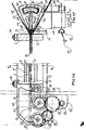
- Figures 1 and 2 of plate 1/7 show the space occupied in depth by the devices necessary for cutting for separation into two layers (13 and 14) of the product. In the example given, this is a weaving loom, therefore a machine equipped with a leaf (19).
- the product first passes between two rules (1 and 2) adjustable in spacing and giving a fixed and precise position to the cutting area.
- the upper rule (1) is carried by the lower rule (2) by means of two threaded columns (38) used to adjust the spacing.
- the rule (2) is supported at the desired level by a crosspiece (3), or two crosspieces (3 and 4).
- crosspieces are connected very rigidly to two guides (16 and 16 '), one on each side of the loom.
- the tubes bringing the oil under pressure can be considered as the means of giving a degree of freedom in translation to the drive system in running of the cutting ribbon, and this without any wear member in use.
- FIGS. 1 and 2 plate 1/7 could, for example, represent the jack (23) fixed in space and its rods linked to the racks (22 and 22 ') by connecting rods, etc.
- FIG. 15 of the board 4/7 appears more favorable in terms of the inertias involved.
- the tape (7) is guided (see Figures 3,4 and 5) between two linings (18) of metal or synthetic material properly treated or loaded for resis ter to wear and promote sliding.
- These linings can be, for example, in sintered bronze loaded with Teflon or in Teflon loaded with graphite and molybdenum disulfide supported by a braided core.
- the formation of an air gap between the faces of the tape (7) and the linings (18) is possible by injection or aspiration of air.
- the example given in Figures 6 and 7 of Plate 2/7 always uses a single ribbon (7) but discontinuous stored in two stores (27 and 27 ').
- the beam cradle (6) is rigidly fixed on the parts (16 and 16 ') connected to the crosspieces (3 and 4).
- the toothless flap (7) receives its continuous advance movements between two reversals of direction of two electric servomotors (31 and 31 ') directly driving the drive pinions (32 and 32'). Meshing with them, but able to slide axially under the thrust or the traction cylinders (35 and 35 1 ), the pinions (33 and 33 ') integral with the rollers (29 and 29') acting directly on the ribbon (7).
- Two pressure rollers (30 and 30 ') keep the ribbon in contact with the rollers (29 and 29').
- the ribbon (7) moves back and forth and vice versa under the effect of the own movement of the rollers (29 and 29 ') and (30 and 30 1 ) and the axes (34 and 34') under the thrust or the traction of the jacks (35 and 35 '), sliding transversely between the fixed jaws (12 and 12'), along the linings (18 and 18 ').
- the beam (6) is made of lightweight composite material as specified above, by giving it a maximum inertia section authorized by the free space on the weaving machine, this beam can be used as a cradle (see Figures 8, 9, 11 and 13 of Plate 3/7).
- the power required will be of the order of KiloWatt to obtain the advances and retreats of the cradle beam.
- the same transmission shaft (56) can also receive, by a gear pair (59,60), directly the rotation of the kinematic chain (61). By meshing this torque (59.6o) and by degreasing the intermittent movement mechanism (55), hence saving wear, we will obtain with less transformation a continuously scrolling cut for ribbon without teeth which could be suitable for a type of woven article.
- Figures 16 and 17 of Plate 5/7 show a reasonable example of a solution for making a versatile device. He is shown with two cutting ribbons with teeth and therefore with asymmetrical alternating scrolling to allow sharpening tooth by tooth.
- the rigid cradle beam (6) is fixed to the supports (16 and 16 ') by adjustable studs (52). Note that in Figures 1, 2, 7, 9 and 16, the drawing of the guide or the fixing of the beam is intentionally kept to show that a versatile device is easily conceivable. But the simple fact of using cylindrical ball bearing slides, ball shoes, oil or air cushion, roller ... or rigid soles would change the design.
- This beam could also be supported by feet articulated around an axis placed as far as possible from the cutting area but vertically above it; the radius of rotation would be of the order of a meter, we would have an arrow less than a micron.
- the two axes (44) of at least each end can be connected by one (or two) crosspiece (s) (45) ending in a fork (53 and 53 ') capable of controlling the advance and the retraction of the axes (34- and 34 ') so sprockets (33 and 33') and rollers (29 and 29 '), or even centering rollers (36 and 36')
- Figure 18 of Plate 6/7 gives a more example detailed but not limiting of use of an interchangeable support (43) of jaw (12) for ribbon (7) single with transverse guide and pins of the type described in FIG. 10 (although in this case, it is preferable that the ribbon is not curved).
- the hydraulic (or pneumatic) chamber (46) is of small volume, that the axes (44) have no head (48) but that they are provided with an air supply ( 54) for the maintenance of an air gap between the ribbon and the linings (not compulsory since the jaws are removable) (18 and 18 ').
- the return to the axes (44) is ensured by springs (53). Stops (52) give the advanced position allowed to each axis (44).
- a cover (47) closes the receptacle of the chamber (46) and the vertical rigidity of the beam (6).
- retreat is provided positively by a second chamber acting in place of the springs (53), or by as many cylinders or thermostatinous membranes as there are axes (44).
- the sharpening devices are not shown. They will obviously be placed outside the cutting area Their action will be controlled by the movement of the cutting ribbons forward and backward, which itself is, let us recall, in synchronism with the stopping or reversing of direction of tape cutting.
Landscapes
- Engineering & Computer Science (AREA)
- Textile Engineering (AREA)
- Treatment Of Fiber Materials (AREA)
- Replacement Of Web Rolls (AREA)
Applications Claiming Priority (2)
| Application Number | Priority Date | Filing Date | Title |
|---|---|---|---|
| FR8407378 | 1984-05-03 | ||
| FR8407378A FR2563846B1 (fr) | 1984-05-03 | 1984-05-03 | Procede destine a separer en deux nappes un produit textile ou paratextile compose de deux nappes retenues entre elles par un reseau de fils tendus en fibres textiles naturelles, synthetiques ou metalliques. |
Publications (1)
| Publication Number | Publication Date |
|---|---|
| EP0161186A1 true EP0161186A1 (de) | 1985-11-13 |
Family
ID=9303915
Family Applications (1)
| Application Number | Title | Priority Date | Filing Date |
|---|---|---|---|
| EP85400856A Withdrawn EP0161186A1 (de) | 1984-05-03 | 1985-05-02 | Verfahren zum Auseinanderschneiden eines textilen oder para-textilen Produktes in zwei Bahnen; das Produkt besteht aus zwei Bahnen, die miteinander verbunden sind durch eine Vielzahl von gesponnenen Fäden aus natürlichen, synthetischen oder metallischen Fasern |
Country Status (2)
| Country | Link |
|---|---|
| EP (1) | EP0161186A1 (de) |
| FR (1) | FR2563846B1 (de) |
Citations (4)
| Publication number | Priority date | Publication date | Assignee | Title |
|---|---|---|---|---|
| FR2375363A1 (fr) * | 1976-12-27 | 1978-07-21 | Girmes Werke Ag | Appareil pour la separation de bandes de peluche double |
| DE2852424A1 (de) * | 1978-12-04 | 1980-06-26 | Scheibler Peltzer & Co | Webmaschine in doppelstuhlbauweise fuer polgewebe |
| DE2905880A1 (de) * | 1979-02-16 | 1980-08-21 | Wolfgang Goebbels | Schneidvorrichtung zum auftrennen von gewebten oder gewirkten doppelbahnen |
| FR2466545A1 (fr) * | 1979-09-27 | 1981-04-10 | Alsacienne Constr Meca | Dispositif de coupe d'un reseau de fils tendus entre deux nappes de tissu |
-
1984
- 1984-05-03 FR FR8407378A patent/FR2563846B1/fr not_active Expired
-
1985
- 1985-05-02 EP EP85400856A patent/EP0161186A1/de not_active Withdrawn
Patent Citations (4)
| Publication number | Priority date | Publication date | Assignee | Title |
|---|---|---|---|---|
| FR2375363A1 (fr) * | 1976-12-27 | 1978-07-21 | Girmes Werke Ag | Appareil pour la separation de bandes de peluche double |
| DE2852424A1 (de) * | 1978-12-04 | 1980-06-26 | Scheibler Peltzer & Co | Webmaschine in doppelstuhlbauweise fuer polgewebe |
| DE2905880A1 (de) * | 1979-02-16 | 1980-08-21 | Wolfgang Goebbels | Schneidvorrichtung zum auftrennen von gewebten oder gewirkten doppelbahnen |
| FR2466545A1 (fr) * | 1979-09-27 | 1981-04-10 | Alsacienne Constr Meca | Dispositif de coupe d'un reseau de fils tendus entre deux nappes de tissu |
Also Published As
| Publication number | Publication date |
|---|---|
| FR2563846A1 (fr) | 1985-11-08 |
| FR2563846B1 (fr) | 1987-04-24 |
Similar Documents
| Publication | Publication Date | Title |
|---|---|---|
| CA1044882A (fr) | Procede et dispositifs de fabrication de corps ou pieces en tissus tridimensionnels | |
| EP2339055B1 (de) | Kreisförmige Nadelmaschine wobei einer Faserstoffbahn durch ein Förderband und eine vertikale Rutsche zugeführt wird | |
| FR2735456A1 (fr) | Procedes et appareil pour la fabrication de pieces annulaires en materiau composite et de preformes pour ces pieces | |
| FR2613653A1 (fr) | Installation d'estampage et de poinconnage | |
| FR2616454A1 (fr) | Appareil de tressage | |
| CH365259A (fr) | Mécanisme provoquant le transport pas à pas d'un tronçon de ruban sur un secteur déterminé, indépendamment des mouvements effectués par le reste du ruban | |
| EP0161186A1 (de) | Verfahren zum Auseinanderschneiden eines textilen oder para-textilen Produktes in zwei Bahnen; das Produkt besteht aus zwei Bahnen, die miteinander verbunden sind durch eine Vielzahl von gesponnenen Fäden aus natürlichen, synthetischen oder metallischen Fasern | |
| FR2887565A1 (fr) | "procede pour ouvrer une nappe dans un appareillage de pre-aiguilletage, et installation mettant en oeuvre un tel procede" | |
| BE1003893A4 (nl) | Snij-inrichting voor dubbelstukweefmachine, meer in het bijzonder aandrijving voor dergelijke snij-inrichting, en weefmachine met dergelijke snij-inrichting uitgerust. | |
| CH633595A5 (fr) | Procede de lainage et appareil pour la mise en oeuvre de ce procede. | |
| EP1599405B1 (de) | Aufspulmaschine mit entkoppeltem lauf für thermoplastische fasern | |
| EP0156738A1 (de) | Vorrichtung zum Aufwickeln eines Stoffes während der verschiedenen Herstellungsphasen | |
| EP0166631A1 (de) | Maschine zur kontinuierlichen Herstellung von Profilbalken aus bewehrtem Material durch dreidimensionales Stricken | |
| CA2704747C (en) | Core winder with a cutting tool associated with a pressure member | |
| FR2562566A1 (fr) | Appareil destine a separer en deux nappes de type velours un produit textile ou paratextile compose de deux nappes retenant tendu entre elles deux un reseau de fils textiles naturels, synthetiques ou metalliques | |
| FR2682129A1 (fr) | Procede et machine pour la realisation d'armatures fibreuses creuses. | |
| FR2585683A1 (fr) | Dispositif d'entrainement pour ensemble de guidage de feuilles de materiau souple destinees a former un assemblage tridimensionnel | |
| US3956806A (en) | Roller fabric fulling machine | |
| US1893957A (en) | Carving machine structure | |
| EP3592892A1 (de) | Nadelmaschine, insbesondere mit elliptischer bewegung zur verfestigung einer faserschicht | |
| BE393206A (de) | ||
| CA1231846A (fr) | Procede et machine de fabrication d'une armature creuse de revolution realisee par tissage tridimensionnel | |
| FR2466545A1 (fr) | Dispositif de coupe d'un reseau de fils tendus entre deux nappes de tissu | |
| KR100537800B1 (ko) | 오일필터용 노치와이어 권선기 | |
| BE706382A (de) |
Legal Events
| Date | Code | Title | Description |
|---|---|---|---|
| PUAI | Public reference made under article 153(3) epc to a published international application that has entered the european phase |
Free format text: ORIGINAL CODE: 0009012 |
|
| 17P | Request for examination filed |
Effective date: 19850510 |
|
| AK | Designated contracting states |
Designated state(s): BE CH DE GB IT LI NL |
|
| 17Q | First examination report despatched |
Effective date: 19871103 |
|
| 19U | Interruption of proceedings before grant |
Effective date: 19870725 |
|
| 19W | Proceedings resumed before grant after interruption of proceedings |
Effective date: 20210201 |
|
| PUAJ | Public notification under rule 129 epc |
Free format text: ORIGINAL CODE: 0009425 |
|
| 32PN | Public notification |
Free format text: NOTIFICATION ETABLIE CONFORMEMENT A LA REGLE 142 CBE (OEB FORM DG5FORM EN DATE DU 12/08/2020) |
|
| STAA | Information on the status of an ep patent application or granted ep patent |
Free format text: STATUS: EXAMINATION IS IN PROGRESS |
|
| PUAJ | Public notification under rule 129 epc |
Free format text: ORIGINAL CODE: 0009425 |
|
| 32PN | Public notification |
Free format text: CONSTATATION DE LA PERTE D'UN DROIT CONFORMEMENT A LA REGLE 112(1) CBE (OEB FORM 2021A EN DATE DU 25/10/2021) |
|
| STAA | Information on the status of an ep patent application or granted ep patent |
Free format text: STATUS: THE APPLICATION IS DEEMED TO BE WITHDRAWN |
|
| 18D | Application deemed to be withdrawn |
Effective date: 20210601 |