EP0161210A1 - Zuführeinrichtung für Drehautomaten mit Achsenlagern - Google Patents
Zuführeinrichtung für Drehautomaten mit Achsenlagern Download PDFInfo
- Publication number
- EP0161210A1 EP0161210A1 EP85810133A EP85810133A EP0161210A1 EP 0161210 A1 EP0161210 A1 EP 0161210A1 EP 85810133 A EP85810133 A EP 85810133A EP 85810133 A EP85810133 A EP 85810133A EP 0161210 A1 EP0161210 A1 EP 0161210A1
- Authority
- EP
- European Patent Office
- Prior art keywords
- block
- bar
- portions
- rotary
- bearing
- Prior art date
- Legal status (The legal status is an assumption and is not a legal conclusion. Google has not performed a legal analysis and makes no representation as to the accuracy of the status listed.)
- Granted
Links
- 239000000463 material Substances 0.000 claims abstract description 59
- 230000002706 hydrostatic effect Effects 0.000 claims abstract description 43
- 230000000694 effects Effects 0.000 claims description 12
- 238000013459 approach Methods 0.000 claims description 7
- 238000003754 machining Methods 0.000 claims description 7
- 210000002445 nipple Anatomy 0.000 claims description 6
- 239000004744 fabric Substances 0.000 claims description 5
- 238000002347 injection Methods 0.000 claims description 5
- 239000007924 injection Substances 0.000 claims description 5
- 238000006073 displacement reaction Methods 0.000 claims description 4
- 230000000149 penetrating effect Effects 0.000 claims description 4
- 239000004033 plastic Substances 0.000 claims description 4
- 229920003023 plastic Polymers 0.000 claims description 4
- 238000004873 anchoring Methods 0.000 claims 1
- 238000005553 drilling Methods 0.000 claims 1
- 230000000717 retained effect Effects 0.000 claims 1
- 239000000126 substance Substances 0.000 claims 1
- 230000009471 action Effects 0.000 description 9
- 238000010276 construction Methods 0.000 description 6
- 238000013461 design Methods 0.000 description 6
- 238000005520 cutting process Methods 0.000 description 5
- 238000000034 method Methods 0.000 description 5
- 239000000243 solution Substances 0.000 description 5
- 230000008569 process Effects 0.000 description 4
- 240000008042 Zea mays Species 0.000 description 3
- 230000008901 benefit Effects 0.000 description 3
- 230000006870 function Effects 0.000 description 3
- 238000009434 installation Methods 0.000 description 3
- 238000012423 maintenance Methods 0.000 description 3
- 230000002093 peripheral effect Effects 0.000 description 3
- 238000012360 testing method Methods 0.000 description 3
- 238000001514 detection method Methods 0.000 description 2
- 238000011161 development Methods 0.000 description 2
- 238000000227 grinding Methods 0.000 description 2
- 230000014759 maintenance of location Effects 0.000 description 2
- 239000002184 metal Substances 0.000 description 2
- 229910052751 metal Inorganic materials 0.000 description 2
- 229910000906 Bronze Inorganic materials 0.000 description 1
- CWYNVVGOOAEACU-UHFFFAOYSA-N Fe2+ Chemical compound [Fe+2] CWYNVVGOOAEACU-UHFFFAOYSA-N 0.000 description 1
- 241000287107 Passer Species 0.000 description 1
- 239000000654 additive Substances 0.000 description 1
- 230000000996 additive effect Effects 0.000 description 1
- 239000000853 adhesive Substances 0.000 description 1
- 230000001070 adhesive effect Effects 0.000 description 1
- 239000010974 bronze Substances 0.000 description 1
- 238000005266 casting Methods 0.000 description 1
- 239000000919 ceramic Substances 0.000 description 1
- 239000011248 coating agent Substances 0.000 description 1
- 238000000576 coating method Methods 0.000 description 1
- 230000006835 compression Effects 0.000 description 1
- 238000007906 compression Methods 0.000 description 1
- KUNSUQLRTQLHQQ-UHFFFAOYSA-N copper tin Chemical compound [Cu].[Sn] KUNSUQLRTQLHQQ-UHFFFAOYSA-N 0.000 description 1
- 230000007423 decrease Effects 0.000 description 1
- 239000012530 fluid Substances 0.000 description 1
- 230000008571 general function Effects 0.000 description 1
- 230000005484 gravity Effects 0.000 description 1
- 238000003780 insertion Methods 0.000 description 1
- 230000037431 insertion Effects 0.000 description 1
- 229910001234 light alloy Inorganic materials 0.000 description 1
- 239000007788 liquid Substances 0.000 description 1
- 238000004519 manufacturing process Methods 0.000 description 1
- 229910001092 metal group alloy Inorganic materials 0.000 description 1
- 150000002739 metals Chemical class 0.000 description 1
- 238000012986 modification Methods 0.000 description 1
- 230000004048 modification Effects 0.000 description 1
- 210000000056 organ Anatomy 0.000 description 1
- 230000035515 penetration Effects 0.000 description 1
- 238000003825 pressing Methods 0.000 description 1
- 230000000750 progressive effect Effects 0.000 description 1
- 239000007787 solid Substances 0.000 description 1
- 229920002994 synthetic fiber Polymers 0.000 description 1
- 238000013519 translation Methods 0.000 description 1
Images


Classifications
-
- B—PERFORMING OPERATIONS; TRANSPORTING
- B23—MACHINE TOOLS; METAL-WORKING NOT OTHERWISE PROVIDED FOR
- B23B—TURNING; BORING
- B23B13/00—Arrangements for automatically conveying or chucking or guiding stock
- B23B13/02—Arrangements for automatically conveying or chucking or guiding stock for turning-machines with a single working-spindle
-
- B—PERFORMING OPERATIONS; TRANSPORTING
- B23—MACHINE TOOLS; METAL-WORKING NOT OTHERWISE PROVIDED FOR
- B23Q—DETAILS, COMPONENTS, OR ACCESSORIES FOR MACHINE TOOLS, e.g. ARRANGEMENTS FOR COPYING OR CONTROLLING; MACHINE TOOLS IN GENERAL CHARACTERISED BY THE CONSTRUCTION OF PARTICULAR DETAILS OR COMPONENTS; COMBINATIONS OR ASSOCIATIONS OF METAL-WORKING MACHINES, NOT DIRECTED TO A PARTICULAR RESULT
- B23Q1/00—Members which are comprised in the general build-up of a form of machine, particularly relatively large fixed members
- B23Q1/72—Auxiliary arrangements; Interconnections between auxiliary tables and movable machine elements
- B23Q1/76—Steadies; Rests
-
- Y—GENERAL TAGGING OF NEW TECHNOLOGICAL DEVELOPMENTS; GENERAL TAGGING OF CROSS-SECTIONAL TECHNOLOGIES SPANNING OVER SEVERAL SECTIONS OF THE IPC; TECHNICAL SUBJECTS COVERED BY FORMER USPC CROSS-REFERENCE ART COLLECTIONS [XRACs] AND DIGESTS
- Y10—TECHNICAL SUBJECTS COVERED BY FORMER USPC
- Y10T—TECHNICAL SUBJECTS COVERED BY FORMER US CLASSIFICATION
- Y10T82/00—Turning
- Y10T82/25—Lathe
- Y10T82/2514—Lathe with work feeder or remover
- Y10T82/2516—Magazine type
- Y10T82/2518—Bar feeder
Definitions
- the present invention relates to a machine tool feeder, in particular for an automatic lathe, comprising bearing blocks, each of which has a circular passage receiving an injection of oil, intended for a machine working a material which is delivered to it in the form of a bar capable of being driven in rotation at high speed by the machine and which is pushed by a flag plunger.
- the presentation GB-A-2 080 160 proposed to make a refueler of the kind in question by placing one behind the other bearing blocks capable of guiding a bar of material to be machined.
- the bearings were ball bearing and were in no way likely to open laterally.
- the various bearing blocks were, in operation, movable in the axial direction, the assembly they formed was tightened, like an accordion, as the bar advanced.
- the invention generally aims to provide a refueler with a very high speed of rotation of the bar, with which said problems find a solution.
- An additional problem which is also solved according to a particular aspect of the present invention, consists in the use of bars of material to be machined of a polygonal profile, in particular hexagonal. It is advisable to provide for this a rotary part with a corresponding polygonal inner contour, but then a lateral opening of the bearing block for the introduction of a bar and / or for the passage of a flag poses a problem difficult to solve.
- the prior art and more precisely the description US-A-3 135 533 which is the only one to provide a hydrostatic bearing capable of opening laterally, does not offer or suggest any solution.
- the realization of a refueler of the kind in question for bars with polygonal profile is also one of the important performances which the invention allows.
- the object of the present invention is to provide a feeder for a machine tool, in particular for an automatic lathe, of the generic type previously stated, with which the disadvantages, inadequacies and limitations known to the prior art are avoided.
- This aim is in particular to provide a feeder of the type in question which is capable of working under the particular conditions which tends to impose the current evolution of machine tools and which is capable, in particular, of guiding a bar of rotating material to be machined at high speed although it is a significant diameter (by that we mean a speed that can reach and even exceed 6,000 or even 10 1000, t / m, with bars whose diameter can reach minus 60 to 80 mm).
- the advantage of the advantageous embodiments proposed lies in particular in a construction that is reliable, simple and effective, in a very rational use of the peculiarities (for many still unexplored) of hydrostatic bearings, in obtaining them, under advantageous conditions, a refueling machine for automatic lathes reaching performances hitherto considered almost impossible, etc ...
- the expression "arc does not not exceeding the order of the half-circumference ". It should be noted that this means that this arc may either be less than 180 0 , or be equal to 180 0 , or also exceed 180 °, but only in a measure such that the two ends of the C shape thus formed leave a space between them which is only a few percent less than the maximum inside diameter. In other words, it is an arc which allows still the lateral introduction of an interior part, taking into account that this interior part has a diameter slightly less than the internal diameter of the part in which the said arc occurs.
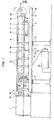
- a feeder generally designated by a reference sign 3.
- This feeder 3 comprises, mounted on two frame uprights 4, a bench 5 preferably having a hollow profile. Seven bearing blocks 6 are fixed on the bench 5, with an interval of approx. Between them each. 25 cm. These seven bearing blocks each include a circular passage in each of which a hydrostatic bearing is established. The seven circular passages are axially aligned, also being aligned with the axis of the headstock spindle 1.
- the bar of material to be machined 2 crosses, in the situation shown in FIG. l, successively each of the seven passages, before entering the doll's spindle.
- These bearing blocks 6 are of the type which will be explained and described in conjunction with FIGS. 2 to 6.
- the width, as shown in fig. 1, that is to say in fact the thickness, of the bearing blocks 6 is approximately 60 mm. Depending on the case, widths significantly less than or greater than this value can be provided.
- the axial dimension of this passage of the bearing block represents 0.5 to 3.0 times the diameter of this passage.
- the headstock of the lathe can drive the bar of material to be machined up to rotational speeds in the region of lO'OOO rpm, despite the fact that the bar can be up to almost 70 mm in diameter.
- a pusher 7 comprising a flag 8 conventionally driven by a cable 9 passing, at the front and at the rear of the feeder, around a pulley 10.
- One of these pulleys is controlled so as to rotate, not necessarily, in a direction such that the pusher is pressed forward, that is to say say against the rear of the bar of material to be machined, in order to push it in the direction of the lathe doll 1.
- the pusher 7 is guided, on an intermediate block ll, by guide means (typically guides in the form of V) 12.
- the two front and rear parts of the tanker are in reality, as shown in fig. l, folded perpendicular to the plane of fig. 1 (towards the rear thereof) of approximately 90 ° , so that the flag 8 is in reality horizontal or almost horizontal.
- the intermediate block 11 provided with guide means 12 can be retracted, perpendicular to the plane of FIG. 1, so that the pusher is no longer in alignment with the material bar 2, but that it is laterally retracted relative to the latter.
- the bearing blocks 6 can open for the introduction of a new bar of material to be machined, when the previous bar is exhausted.
- a new bar of material to be machined ready to enter into place in the bearing blocks 6, when necessary and that, for this, the blocks will have opened in a manner which will be explained further.
- the pusher 7, with its flag 8 and its support and guide arrangement 11, 12, can be retracted laterally.
- the new bar 14 arrives, in the axial direction, practically up to the position of the rear of the pusher 7. It is understood that, when the latter is retracted (and the bearing blocks are open) the new bar 14 can be put in place, being then entirely located behind the headstock 1.
- each bearing block 6 provides for the bar 2, each a hydrostatic type bearing.
- Each bearing block therefore has an inlet 16 for pressurized oil, to which an oil pipe 17 leads, coming from an oil pressure pump 18.
- the pressurized oil is distributed similarly to each of the seven bearing blocks; in addition, pressurized oil must also be supplied to different hydraulically controlled members. If necessary, the same pressurized oil can be used for this, which is supplied to the hydrostatic bearings, or else a different oil.
- oil we mean all li hydraulic fluid suitable for a hydrostatic bearing, which liquid could be something other than real oil.
- the present embodiment provides for them to operate hydraulically, but other actuation modes, for example pneumatic, electromagnetic, etc., would also be possible.
- a retention tank is provided under the bench 5 and around it, to collect the oil which escapes from the hydrostatic bearings. From this retention tank, the oil naturally returns to the oil pressure pump 18, preferably passing through an intermediate reservoir, not shown.
- the oil pressure is approximately 3 atm, the oil used having an ISO oil viscosity of 100.
- the oil flow rate is approximately 1 liter per minute and in stages hydrostatic, so that the oil flow is not very important.
- detection means detect the moment when the flag approaches a landing block.
- the rear end of the bar 2 stops passing through the passage of a bearing block 6, successively from the last bearing to the first, the supply of oil pressure in the bearing concerned could be cut off.
- the arrival of oil in the bearing block passes through a capillary passage which limits the flow of oil, so that one can easily do without cutting off the arrival of oil, even in bearing blocks which are no longer occupied by the bar of material to be machined 2 (the pusher 7 in principle has a markedly smaller diameter, and moreover only its front end is rotatable, so that it does not there is no effect hydrostatic bearing when it is this pusher 7 which passes through the passage of a bearing block 6).
- the alignment precision of the passages of the bearing blocks is of the order of ⁇ 0.1 mm, this precision being sufficient taking into account the peculiarities of the hydrostatic bearing refueller. This does not prevent from rotating in these bearings, up to approximately 10,000 rpm, bars whose diameter can go up to 80 mm.
- the product limit "rotation speed x diameter" is no longer given by the feeder, but by the characteristics of the lathe (machining questions, also question of drive power).
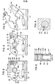
- each bearing block 6 comprises two block portions, respectively 20 and 21, the portion 20 being fixedly mounted on the bench 5, while the portion 21 is pivotally mounted on the portion 20, so as to allow, as will be seen, the opening of the hydrostatic bearing.
- the block portion 20, fixed has the shape of a U, as shown in FIG. 5, this structure is naturally not compulsory.
- the block portion 21 pivots relative to the fixed block portion 20 about an axis 22.
- the bearing block is shown in the closed and locked state, and we see at 23 the passage mentioned above, intended to guide the bar of material to be machined 2.
- half of this passage is hollowed out in the block portion 20 while the other half is hollowed out in the block portion 21.
- These two block portions are preferably made of ferrous metal or else of a light alloy with high resistance, and the passage 23 could present its inner wall directly in the two portions 20 and 21.
- block portions should not necessarily be two in number; a higher number could do the trick, for example, three block portions, two of which, upper, would open on one side and the other by pivoting on the third portion, lower and fixed.
- Such an embodiment would require an orientation of the flag 8 (fig. 1) not approximately horizontally, (like the embodiment described here) but vertical. It is clear that the number of socket sectors (24) should correspond to the number of block portions.
- a cylinder-piston arrangement 27 actuates a lever 28, pivoted at 29, and provided with an upper transverse bar 30.
- the lever 28 actually comprises two similar vertical or oblique parts, connected by the transverse bar 30.
- FIG. 5 shows their arrangement. Note that two variants are possible. According to the first, the two lever parts 28 are arranged outside the block portion 21, the cylinder-piston arrangement 27 also being arranged outside this portion and most simply acting on only one of the two lever arm 28.
- the two arms of the lever 28 are located inside the block portion 21, in the shape of a U, and the piston cylinder arrangement 27 is arranged in the middle, acting on a transverse bar which connects, similarly to the transverse bar 30, the two lower ends of the two parts of the lever 28.
- FIGS. 2 to 5 represent the first of these two variants.
- the bar 30 compresses, with a slight “stopping " effect , the domed or conical head 31, which presses the block portion 21 completely against the block portion 20.
- the places by which the two portions 20 and 21 are pressed against each other mainly comprise the ends of the half-sectors 24a and 24b, with, as the case may be, a small portion of the material of the main body of the portions 20 and 21, so as to ensure adequate support, which genuinely closes the passage 23 in a complete manner.
- Fig. 3 represents the situation we have when the means previously mentioned and not shown have detected the fact that the flag 8 approaches the bearing block concerned. At this time, it is no longer the bar 2, but the rod of the pusher 7 which is in the passage 23, that is to say that the part passing through this passage is no longer rotatable.
- the cylinder 27 actuates its piston in a manner which, as shown in FIG. 3, moves the lever 28 to a position where its bar 30 is no longer supported on the locking head 31.
- elastic support means 34, 35 shown, in dotted lines, only at fig. 3, cause a slight rise in the part 21, so that it appears, on the side of the passage 23 opposite the pivot point 22, a gap through which the flag 8 can pass through the bearing block, as shown in fig. 3.
- this longitudinal pivot rod 22 comprises, either over its entire length, or at least at the places where it passes through a pivoting part of each portion of block 21, a recess 36 into which a pin 37 penetrates driven through the 'rear of portion 21.
- this semi-imperative control arrangement easily allows the block portion 21 to rise slightly under the effect of the arrangement 34.35, as soon as the support on the head 31 has ceased , but that it also makes it possible to imperatively control the lifting of all the portions 21, that is to say the true opening of all the passages 23, by a simple rotation of the rod 22.
- the block portion 21 must be closed and relocked, a rotation in the other direction of the rod 22 brings all the portions 21 in complete contact with the corresponding portion 20, which allows the locking of the bar 30 acting on the locking head 31.
- the rod 22 again turns a few degrees in the other direction, to allow the opening of the bearing block when it is unlocked following detection of the approach of the flag 8.
- the sockets or semi-sockets 24a, 24b are advantageously fixed in a non-permanent manner, by suitable means, respectively on the block portions 20 and 21, so that these socket sectors 24a, 24b can be changed, to modify the internal diameter of the passage 23.
- an opening diameter, in the body of the portions 20 and 21, of 100 mm it is possible, by means of different sockets 24 (each time two half-sockets) establish passage diameters which may be in the range of 10 to 80 mm.
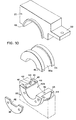
- Figs. 7, 8 and 9 represent a part of a different embodiment from that considered so far.
- this second embodiment has little difference, other than the fact that the pusher must have a particular construction as shown in FIG. 11.
- what has been seen in connection with FIGS. 2 to 6, remains valid, with however this difference that, in the second embodiment, it is no longer the bar of material to be machined, of round profile, which constitutes the rotary part of the hydrostatic bearing whose non-rotary part is formed of the portions 20 and 21, but it is a rotary intermediate member, visible in FIGS.
- the external cylindrical part of the sleeve 40 rotates in the portions bearing block 20, 21, exactly as the bar of material to be machined 2 rotated in this bearing in the embodiment previously considered. It is noted that the hydrostatic pressure of the oil is such that the two parts 40a, 40b, which form the bush 40, remain held together, as shown by tests carried out.
- the sleeve 40 also has a part in radial projection 43, then an axial overhang 44, while the block portions 20 and 21 have, around their inner cylindrical surface, axial edges 45 which penetrate under the edges in overhang 44, as shown in FIG. 9.
- connection means between the two half-sockets 40a and 40b to further reinforce the effect of maintaining the connection which is due to the hydrostatic pressure.
- These additional connection means consist of plates 46, fixed to one end of each half-sleeve and where each stud 47 is anchored, having a groove 48, and penetrating into a corresponding opening 52 of the end of half-sleeve. facing him.
- Balls 49 strongly pressed towards the middle of the bush 40 by springs 50 held by screws 51, then engage in the groove 48 of each stud 47, in a manner which keeps the half-bushings firmly linked. one to the other.
- the construction provided for the rotary intermediate member 40, 41 is easily understood by considering FIGS. 7 to 10.
- the internal diameter of the sleeve 40 is greater than the largest dimension of the hexagonal profile 42 of the sections of cheek with hexagonal internal contour 41. This avoids direct contact between the bar of material to be machined, with a hexagonal profile, and the sleeve 40.
- the parts 40a and 40b of the sleeve 40, as well as the cheek portions 41, defining the hexagonal inner guide contour are preferably made of a material that is both solid and light, given their high speed of rotation.
- metals can suitably, lighter and equally resistant materials have proven to be particularly advantageous, in particular bakelized fabric (canvas), as well as other light materials, identical to those which are recommended for the half-sockets 24a, 24b.
- the plates 46 and the pins 47 as well as the balls 49 are preferably metallic.
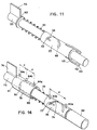
- a pusher 55 provided with a flag 56, at the base similar to the pusher 7 of FIG. l.
- the pusher 55 is threaded through a sleeve or ring 57, which is tone na - Gee a helical slot or slide 58, which extends angularly over slightly more than 180 °.
- a pin 59 is driven into an adequate radial bore in the pusher so as to be engaged in the slot 58, but without its outer end exceeding the outside diameter of the socket 57.
- the pusher 55 carries a washer 60 against which the rear end of a compression spring 61 rests, the end of which front is in abutment against the socket 57.
- this socket 57 tends, under the effect of the spring 61, to be driven towards the front of the pusher, its angular position then being determined by the position of the rear end of the helical slot 58.
- the bushing or ring 57 carries leaf springs 63, at the front of which are lugs 62, having an oblique front side 64.
- the pin 62 goes arrive in a space "e" between the two edges, facing each other, of the two cheek portions 41.
- the pins 62 will penetrate into these spaces, and, due to the adequate dimensioning of the assembly, the oblique sides 64 of the two pins 62 will come to bear just against the edge 'at' of the inner circumference of the sleeve 40.
- the resistance of the spring 61 is more weak than the resistance of the two leaf springs 63, following the advance of the pusher 55 will continue to compress the spring 61, the lugs remaining in place against the edges "a", until the ring 57 having practically turned a half-turn, the pin 59 is at the front end 65 of the helical groove 58.
- the pins 62 will have positioned the rotary intermediate member 40, 41 exactly in the desired position for opening the bearing block, taking into account that, as shown in Fig. 11, the two pins 62 are, in their two extreme positions, angularly offset by 180 0 , in alignment with the direction of the flag 56.
- the helical groove 58 must allow a total stroke of approximately 180 °. It is not annoying that it is slightly greater, the total length of the groove must in any case be increased to allow the stroke of 180 0 taking into account the diameter of the pin 59.
- the total angular stroke being equal or very slightly greater than 1800, the important thing is the position of the socket and of the pins when this socket is closest to the flag, that is to say when the pin 59 is located in the end 65 of the groove 58. It is therefore mainly the position of this front end 65 of the groove that is of importance.
- the repositioning lugs could also be fixed directly to the socket 57, without the possibility of radial elastic retraction.
- the polygonal outline could be other than hexagonal, for example octagonal, or possibly square.
- cooperation of the "pin 59 / helical groove 58" type could also be carried out in the other direction, the helical groove being cut out from the cylindrical surface of the pusher and the pin being secured to the ring.
- this embodiment according to Figs. 12 and 13 uses elements 46 'to 52', similar to elements 46 to 52 of the embodiment according to FIGS. 7 to 9.
- the retaining arrangement 43-45 shown diagrammatically in FIG. 10 could also have applied to the embodiment of the intermediate rotary mobile according to FIGS. 12 and 13, but in this case, a easier-to-make retaining arrangement (68, 69) has been chosen (which will be described later).
- This notch, 72 which is established between the parts which form the sectoral portions of the rotary member, is established this time, like a mortise, all through the rotary member. So we have, in the rotary organ closed, two diametrically opposite notches 72 which pass through the entire rotary member, that is to say are formed in the cheek parts 71 and the middle part 66.
- the pusher assembly of FIG. 14 comprises a pusher 73 provided, at its rear end, with a flag 74, and supporting a ring or sleeve 75 threaded on the pusher 73 and capable of moving angularly and axially with respect thereto.
- a socket 81 is fixedly mounted (driven and / or pinned) on the pusher 73.
- this pusher 73 has a cylindrical part 82 with a larger diameter, as a variant this part 82 could also be a socket fixedly mounted (driving and / or pinning) on the pusher 73.
- socket or movable ring 75, the rear fixed socket 8i and the front part (or fixed socket) 82 all have, at least approximately, the same outer diameter, so that these parts find passage in the inner polygonal contour 67 of the intermediate rotary mobile in the closed state.
- the ring 75 also includes a helical notch 76 in which is engaged a pin 77.
- a helical spring 78 pushes the ring 75 forward, the rear of this spring penetrating inside the sleeve 81, in a annular space 79.
- the sleeve 81 has at the front an internal diameter greater than the diameter of the plunger 73.
- the rear of the spring 78 bears against an internal shoulder 80 of the sleeve 81.
- the axial stroke of the ring 75 relative to the pusher 73 is preferably delimited in the forward direction by abutment against the part with a larger diameter (or the fixed bush) 82__ and in the rear direction by abutment against the front face 85 of the socket 81.
- the ends of the helical notch 76 no longer have (or no longer necessarily have) the function of limiting the stroke of the ring 75 on the pusher 73
- this helical notch 76 will be made a little longer than the helical notch 58 of FIG. 11, to ensure that the sockets 81 and 82 are indeed limiting the movement of the ring 75.
- the sleeve 75 was designed in the step where it is slightly retracted from its most advanced position on the pusher, that is to say from its position where it is in abutment against the part 82.
- the socket 75 is provided, in the vicinity of its front end and in an angular position aligned with the flag 74 when the socket 75 is in its most advanced axial position, of a lug 83a, formed by a pin or similar member driven (or firmly planted in another suitable manner) in the thickness of the socket 75.
- This lug 83a plays, for the first part of the angular positioning process of the rotary mobile, the same role as the lug 62 of fig. 11.
- the "search for the notch" is carried out in the same way, in the sense that the lug 83 abuts against the side of the cheek 71, then, being stopped axially while the flag continues to advance, this lug rotates, sliding around the cylindrical edge 70 of the cheek 71, until it enters one of the notches 72 (fig. 12).
- the process becomes different from what it was with the button in fig. 11. Indeed, as the notch 72 passes through all the rotary mobile, the lug 83a, as soon as it has found the notch 72, is pushed forward by the effect of the spring 78 and, sliding then axially on the pusher, it also moves angularly around the pusher, due to the action of the helical groove 76 and the pin 77. When the ring 75 thus moves under the effect of the spring 78, the lug 83a slides axially inside the notch 72 (fig.
- a second lug for holding, 83b, aligned with the first, active lug, 83a.
- the distance d between the lugs 83a and 83b is less than the thickness (l, fig. 13) of the rotary mobile.
- the presence of the second lug, 83b is not compulsory, it is however advantageous.
- the second lug 83b makes it possible to lighten the aforementioned requirement relating to the longitudinal stroke of the ring 75 on the pusher (not to exceed f).
- the lug 83b has already entered it at the rear and can, if necessary, complete its angular positioning action.
- the three fixed retaining lugs, 84a, 84b and 84c, which are similarly planted with the lugs 83a, 83b, are also provided in the rear bushing 81 fixed on the pusher.
- the pins 84a, 84b and 84c are in angular alignment with the flag 74, and they also have a spacing "d" between them (fig. 14) which must not exceed the total thickness of the rotary mobile f (fig. 13) .
- the distance between the lug 84a, the most advanced on the socket 81, and the lug 83b, the most moved back on the ring 75 must also, even in the most advanced position of the ring 75, not exceed this distance.
- front part (or fixed front socket) 82 with surface means which increase the friction of this part 82 against the sides of the inner polygonal contour.
- These means could for example consist of an elastic or semi-elastic coating of the part 82, or in another arrangement capable of providing the friction necessary to retain the rotary mobile from the inside.
- the middle parts and the cheek parts of the sectoral portions of the rotary member could be produced in a monolithic manner, in a single cast, molded or thermoformed part.
- the means for retaining the rotary sectoral portion in the block portion, at the time of opening thereof consist of two pins 68 engaged respectively in a semi-circular recess 69 of the semi-circular portion cheek piece 71.
- the sectoral cheek portions extend radially beyond the cylindrical bearing surface of the middle part 66, to border, on each side, the block portions 20 ′, 21 '(similar, in terms of their form and general functions, to their homonyms in Figs. 2 to 4).
- the pins 68 cooperate with the recesses 69 in a manner which maintains the portion of the rotary mobile in the non-rotating portion of the bearing block.
- the opening of the bearing block and the rotating portions, first for the passage of the dra skin then for the introduction of a new bar of material to be machined, is therefore carried out with certainty in an adequate manner.
- This embodiment of the retaining means is easy to manufacture and allows easy assembly of the parts present.
- the assembly is easy as well when, as shown in fig. 12 and 13, the rotary movable portions are in several separate parts (a central portion, two parts by cheek), when the movable portions are rotatable, as is also seriously in- v isagé in a single monolithic piece, made of molded or thermoformed material (for example, a synthetic material loaded with a metallic or ceramic additive increasing its mechanical tenacity and its resistance to wear).
- this stop buffer 87 located at the end of a stop lever 88, which is pivoted at 89 at or near the axis of articulation 22 of the block portions bearing (see fig. 2 to 4).
- the stop buffer 87 and the lever 88 are already pulled down by their own weight.
- a spring 90 hooked, on the one hand, to the lever 88 and, on the other hand, to a fixed part 91, can ensure the action of the pad 87.
- a support intervenes between the stop lever 88 and a fixed part, for example adjoining the part 20 of the bearing block, symbolized at 92 in FIG. 12.
- the stopping (or retaining) means 86, 87 are located in FIG. 12, in a middle position, it is clear that they could occupy another situation along the periphery of the upper rotating portion.
- Other stopping means may also prove to be adequate, one could for example use an engagement, with smooth friction or notch, between the pins 68 and the external lateral wall of the recess 69, when the block portion in the open state of the bearing, it is "suspended" from the pins 68.
- the embodiment of the rotary mobile represented in FIGS. 12 and 13 proved to be very advantageous in the tests for producing a tanker such as that shown in FIG. 1, with progressive sequential opening of the bearings according to FIGS. 2 to 4, for bars of material to be machined with a non-circular profile.
- the number of bearing blocks could be greater or less than that provided for in FIG. 1.
- the length of the section on which the bearing blocks are located is approximately 2 m.
- the total length of the tanker is approximately 3 m.
- a particularity of the proposed design also consists in the use of material which is both resistant and light, such as for example a bakelized or plasticized fabric, a self-lubricating plastic material, etc. These materials have proven to be advantageous for constituting the parts of a hydrostatic bearing.
- material which is both resistant and light such as for example a bakelized or plasticized fabric, a self-lubricating plastic material, etc.
Landscapes
- Engineering & Computer Science (AREA)
- Mechanical Engineering (AREA)
- Turning (AREA)
- Forging (AREA)
- Apparatuses For Bulk Treatment Of Fruits And Vegetables And Apparatuses For Preparing Feeds (AREA)
- Formation And Processing Of Food Products (AREA)
- Auxiliary Devices For Machine Tools (AREA)
Priority Applications (1)
| Application Number | Priority Date | Filing Date | Title |
|---|---|---|---|
| AT85810133T ATE39634T1 (de) | 1984-03-27 | 1985-03-26 | Zufuehreinrichtung fuer drehautomaten mit achsenlagern. |
Applications Claiming Priority (2)
| Application Number | Priority Date | Filing Date | Title |
|---|---|---|---|
| CH1541/84 | 1984-03-27 | ||
| CH1541/84A CH657794A5 (fr) | 1984-03-27 | 1984-03-27 | Bloc-palier, ravitailleur, notamment pour tour automatique, comprenant de tels blocs-paliers, utilisation de ce bloc-palier. |
Publications (2)
| Publication Number | Publication Date |
|---|---|
| EP0161210A1 true EP0161210A1 (de) | 1985-11-13 |
| EP0161210B1 EP0161210B1 (de) | 1989-01-04 |
Family
ID=4212827
Family Applications (1)
| Application Number | Title | Priority Date | Filing Date |
|---|---|---|---|
| EP85810133A Expired EP0161210B1 (de) | 1984-03-27 | 1985-03-26 | Zuführeinrichtung für Drehautomaten mit Achsenlagern |
Country Status (10)
| Country | Link |
|---|---|
| US (1) | US4628779A (de) |
| EP (1) | EP0161210B1 (de) |
| JP (1) | JPS6150701A (de) |
| AT (1) | ATE39634T1 (de) |
| AU (1) | AU589073B2 (de) |
| BR (1) | BR8501370A (de) |
| CH (1) | CH657794A5 (de) |
| DE (1) | DE3567160D1 (de) |
| ES (1) | ES285634Y (de) |
| ZA (1) | ZA852167B (de) |
Cited By (8)
| Publication number | Priority date | Publication date | Assignee | Title |
|---|---|---|---|---|
| FR2589380A1 (fr) * | 1985-11-05 | 1987-05-07 | Bechet Freres Sa | Chargeur de barres pour machines-outils automatiques |
| EP0224894A3 (en) * | 1985-12-04 | 1988-12-28 | I.E.M.C.A. S.P.A. Industria Elettromeccanica Complessi Automatici | Guide channel structure for bars of variable diameter |
| EP0214585A3 (de) * | 1985-09-12 | 1989-01-11 | I.E.M.C.A. S.p.a. Industria Elettromeccanica Complessi Automatici | Stangenführungsvorrichtung zur Verwendung mit einer Vorrichtung zum Zuführen von Stangen zu Werkzeugmaschinen |
| FR2687943A1 (fr) * | 1992-03-02 | 1993-09-03 | Bechet Freres Sa | Embarreur pour tour. |
| FR2701661A1 (fr) * | 1993-02-17 | 1994-08-26 | Bechet Freres Sa | Embarreur à entraînement multiple. |
| US5970830A (en) * | 1997-07-18 | 1999-10-26 | Vn Sa | Bar feeder for feeding a machine tool, in particular an automatic lathe |
| EP1291127A1 (de) * | 2001-09-10 | 2003-03-12 | Lns S.A. | Zuführvorrichtung zum Zuführen von Stangen und Entfernen von Abfallstücken |
| CN117884664A (zh) * | 2024-02-19 | 2024-04-16 | 国网青海省电力公司 | 一种电力装备调相机转子生产流水线 |
Families Citing this family (17)
| Publication number | Priority date | Publication date | Assignee | Title |
|---|---|---|---|---|
| US4739682A (en) * | 1986-07-03 | 1988-04-26 | Birkestrand Orville J | Tube end finishing machine |
| IT1262147B (it) * | 1993-06-25 | 1996-06-19 | Piegatrici Macch Elettr | Procedimento di intestatura barre e gruppo intestatore barre adottante tale procedimento |
| US5535653A (en) * | 1993-09-08 | 1996-07-16 | J. F. Berns Company, Inc. | Bar stock supporting and feeding apparatus |
| USD383960S (en) * | 1995-07-10 | 1997-09-23 | Tri Tool, Inc. | Tube end squaring tool |
| JP3262745B2 (ja) * | 1997-07-30 | 2002-03-04 | 株式会社育良精機製作所 | 棒材供給機 |
| JP3405936B2 (ja) * | 1999-04-28 | 2003-05-12 | 哲夫 稲葉 | 自動旋盤用棒材支持装置 |
| CA2431137A1 (en) | 2000-12-18 | 2002-06-27 | Cardemon Inc., D/B/A Car-Tec Company | Adjustment method and apparatus for a boring tool |
| US7029209B2 (en) | 2000-12-18 | 2006-04-18 | Cardemon, Inc. | Slidable boring tool with fine adjustment |
| WO2005051581A1 (ja) * | 2003-11-28 | 2005-06-09 | Citizen Watch Co., Ltd. | 数値制御自動旋盤の棒材供給装置 |
| US20080041200A1 (en) * | 2006-02-22 | 2008-02-21 | Kneebusch William C | Method and apparatus for feeding bars into a cutting lathe |
| ATE424952T1 (de) * | 2006-04-27 | 2009-03-15 | Lns Sa | Einrichtung zum sequenziellen zuführen von stangen in eine werkzeugmaschine |
| CN101439469B (zh) * | 2008-12-17 | 2010-06-09 | 合肥工业大学 | 机床液体动压中心架 |
| US9238556B2 (en) * | 2011-01-18 | 2016-01-19 | Leoni-Kabel Holding Gmbh | Apparatus for the automated feed of connecting elements to a processing unit and feed hose for the connecting elements |
| JP6482035B2 (ja) * | 2013-12-11 | 2019-03-13 | エルエヌエス マネジメント エス・アー・エール・エルLNS Management Sarl | 棒送り装置 |
| JP6193803B2 (ja) * | 2014-05-19 | 2017-09-06 | 株式会社松浦機械製作所 | 振れ止め装置 |
| JP6284599B1 (ja) * | 2016-09-14 | 2018-02-28 | 本田技研工業株式会社 | 電極チップ取付装置 |
| KR102029692B1 (ko) * | 2019-07-19 | 2019-10-08 | 정성기 | 스위스 타입 머시닝 센터를 위한 모재 공급 장치 |
Citations (7)
| Publication number | Priority date | Publication date | Assignee | Title |
|---|---|---|---|---|
| FR536510A (fr) * | 1921-06-06 | 1922-05-04 | Dispositif spécial support de barres pour tours à décolleter | |
| US1906577A (en) * | 1928-06-07 | 1933-05-02 | Rk Leblond Machine Tool Co | Steady rest for crank shaft lathes |
| US3145513A (en) * | 1962-12-13 | 1964-08-25 | Gordon H Porath | Steady rests |
| GB1434267A (en) * | 1973-12-13 | 1976-05-05 | Twyford Moors Aircraft & Eng | Bar holder arrangement for bar stock material to be fed to a machine tool |
| SU617233A1 (ru) * | 1977-03-05 | 1978-06-30 | Предприятие П/Я Р-6564 | Гидролюнет |
| SU645810A2 (ru) * | 1977-03-16 | 1979-02-05 | Предприятие П/Я В-8424 | Люнет |
| SU654384A2 (ru) * | 1977-09-23 | 1979-03-30 | Предприятие П/Я В-8424 | Люнет |
Family Cites Families (11)
| Publication number | Priority date | Publication date | Assignee | Title |
|---|---|---|---|---|
| US3147653A (en) * | 1960-11-25 | 1964-09-08 | Arco Feed Inc | Stock feeding apparatus |
| AU425908B2 (en) * | 1968-04-10 | 1972-07-10 | Rast Products Pty. Ltd | Improvements in and relating tothe bar feed tubes of lathes |
| GB1492989A (en) * | 1974-08-19 | 1977-11-23 | Hagenuk Neufeldt Kuhnke Gmbh | Control means in a bar holder and feeder coupled to an automatic machine tool |
| SU543493A1 (ru) * | 1975-05-06 | 1977-01-25 | Педприятие П/Я В-8424 | Люнет |
| US4037733A (en) * | 1975-07-29 | 1977-07-26 | Hagenuk Vormals Neufeldt And Kuhnke G.M.B.H. | Bar holder arrangement for bar stock material to be fed to a machine tool |
| IT1120340B (it) * | 1979-04-13 | 1986-03-19 | Ind Elettromeccanica Complessi | Dispositivo per migliorare l'alimentazione di una barra a torni automatici per la lavorazione di barre |
| US4406190A (en) * | 1980-05-16 | 1983-09-27 | White-Bsa Tools Limited | Bar stock feed apparatus for a machine tool |
| DE3024766C2 (de) * | 1980-06-30 | 1982-09-02 | Index-Werke Kg Hahn & Tessky, 7300 Esslingen | Zuführeinrichtung für Stangenmaterial an Drehmaschinen |
| ES504082A0 (es) * | 1980-07-18 | 1982-12-01 | Sameca Sa | Equipo para el guiado de la bana de material, de diversos diametros, mecanizados en un torno automatico. |
| JPS57156103A (en) * | 1981-03-23 | 1982-09-27 | Miyano Tekkosho:Kk | Automatic feed device of bar material |
| DE3370598D1 (en) * | 1982-09-10 | 1987-05-07 | Fmb Maschinenbau Gmbh | Bar feeding apparatus for an automatic lathe |
-
1984
- 1984-03-27 CH CH1541/84A patent/CH657794A5/fr not_active IP Right Cessation
-
1985
- 1985-03-15 US US06/712,072 patent/US4628779A/en not_active Expired - Lifetime
- 1985-03-19 AU AU40106/85A patent/AU589073B2/en not_active Ceased
- 1985-03-22 ZA ZA852167A patent/ZA852167B/xx unknown
- 1985-03-25 JP JP60058646A patent/JPS6150701A/ja active Granted
- 1985-03-26 EP EP85810133A patent/EP0161210B1/de not_active Expired
- 1985-03-26 DE DE8585810133T patent/DE3567160D1/de not_active Expired
- 1985-03-26 BR BR8501370A patent/BR8501370A/pt not_active IP Right Cessation
- 1985-03-26 ES ES1985285634U patent/ES285634Y/es not_active Expired
- 1985-03-26 AT AT85810133T patent/ATE39634T1/de not_active IP Right Cessation
Patent Citations (7)
| Publication number | Priority date | Publication date | Assignee | Title |
|---|---|---|---|---|
| FR536510A (fr) * | 1921-06-06 | 1922-05-04 | Dispositif spécial support de barres pour tours à décolleter | |
| US1906577A (en) * | 1928-06-07 | 1933-05-02 | Rk Leblond Machine Tool Co | Steady rest for crank shaft lathes |
| US3145513A (en) * | 1962-12-13 | 1964-08-25 | Gordon H Porath | Steady rests |
| GB1434267A (en) * | 1973-12-13 | 1976-05-05 | Twyford Moors Aircraft & Eng | Bar holder arrangement for bar stock material to be fed to a machine tool |
| SU617233A1 (ru) * | 1977-03-05 | 1978-06-30 | Предприятие П/Я Р-6564 | Гидролюнет |
| SU645810A2 (ru) * | 1977-03-16 | 1979-02-05 | Предприятие П/Я В-8424 | Люнет |
| SU654384A2 (ru) * | 1977-09-23 | 1979-03-30 | Предприятие П/Я В-8424 | Люнет |
Cited By (10)
| Publication number | Priority date | Publication date | Assignee | Title |
|---|---|---|---|---|
| EP0214585A3 (de) * | 1985-09-12 | 1989-01-11 | I.E.M.C.A. S.p.a. Industria Elettromeccanica Complessi Automatici | Stangenführungsvorrichtung zur Verwendung mit einer Vorrichtung zum Zuführen von Stangen zu Werkzeugmaschinen |
| FR2589380A1 (fr) * | 1985-11-05 | 1987-05-07 | Bechet Freres Sa | Chargeur de barres pour machines-outils automatiques |
| EP0224894A3 (en) * | 1985-12-04 | 1988-12-28 | I.E.M.C.A. S.P.A. Industria Elettromeccanica Complessi Automatici | Guide channel structure for bars of variable diameter |
| FR2687943A1 (fr) * | 1992-03-02 | 1993-09-03 | Bechet Freres Sa | Embarreur pour tour. |
| FR2701661A1 (fr) * | 1993-02-17 | 1994-08-26 | Bechet Freres Sa | Embarreur à entraînement multiple. |
| EP0612574A1 (de) * | 1993-02-17 | 1994-08-31 | Bechet Freres (Societe Anonyme) | Stangenführung mit mehreren Antrieben |
| US5970830A (en) * | 1997-07-18 | 1999-10-26 | Vn Sa | Bar feeder for feeding a machine tool, in particular an automatic lathe |
| EP1291127A1 (de) * | 2001-09-10 | 2003-03-12 | Lns S.A. | Zuführvorrichtung zum Zuführen von Stangen und Entfernen von Abfallstücken |
| CN117884664A (zh) * | 2024-02-19 | 2024-04-16 | 国网青海省电力公司 | 一种电力装备调相机转子生产流水线 |
| CN117884664B (zh) * | 2024-02-19 | 2024-06-11 | 国网青海省电力公司 | 一种电力装备调相机转子生产流水线 |
Also Published As
| Publication number | Publication date |
|---|---|
| CH657794A5 (fr) | 1986-09-30 |
| US4628779A (en) | 1986-12-16 |
| ES285634U (es) | 1985-10-01 |
| AU589073B2 (en) | 1989-09-28 |
| ZA852167B (en) | 1985-11-27 |
| JPH034321B2 (de) | 1991-01-22 |
| AU4010685A (en) | 1985-10-03 |
| JPS6150701A (ja) | 1986-03-13 |
| BR8501370A (pt) | 1985-11-26 |
| DE3567160D1 (en) | 1989-02-09 |
| EP0161210B1 (de) | 1989-01-04 |
| ES285634Y (es) | 1986-05-01 |
| ATE39634T1 (de) | 1989-01-15 |
Similar Documents
| Publication | Publication Date | Title |
|---|---|---|
| EP0161210B1 (de) | Zuführeinrichtung für Drehautomaten mit Achsenlagern | |
| EP0281511B1 (de) | Drahtschneidevorrichtung | |
| EP1930111A1 (de) | Wirbelkopf und seine Anwendung | |
| FR2513492A1 (fr) | Dispositif pour le retournement d'objets en forme de tiges tels qu'en particulier des cigarettes | |
| EP0806264B1 (de) | Werkzeugmaschine mit Exzenterspindel | |
| EP1317329B1 (de) | Bohrkopf | |
| EP0071518A1 (de) | Stangennachschubeinrichtung | |
| FR3064511B1 (fr) | Mandrin de serrage a coulisseaux inclines | |
| FR2476527A1 (fr) | Dispositif de retenue de pieces pour les operations de honage | |
| FR2566690A1 (fr) | Taraudeuse | |
| EP1075910A1 (de) | Maschine zum Schneiden von Papierrollen | |
| FR2657281A1 (fr) | Machine pour tailler des engrenages. | |
| EP3307462B1 (de) | Drehmaschine und führungsbuchse | |
| EP0473739B1 (de) | Drahtrichtvorrichtung | |
| EP1088613A1 (de) | Bearbeitungskopf | |
| CH647968A5 (en) | Rotary rest | |
| FR2701414A1 (fr) | Taraud machine. | |
| FR2584970A1 (fr) | Dispositif de coupe pour machines de formage d'articles enroules | |
| EP0533027B1 (de) | Führungsbuchse | |
| FR2497701A1 (fr) | Dispositif d'alimentation continue d'une machine pour la fabrication de pieces a partir d'un fil ou d'une barre | |
| CH672446A5 (en) | Machine-tool bar-feed mechanism - has tube rear part movable sideways for reloading of front part | |
| EP0661136B1 (de) | Verfahren zum Honen der Oberfläche eines Teiles und Honwerkzeug zur Durchführung des Verfahrens | |
| CH333276A (fr) | Machine-outil comprenant un tambour-revolver | |
| EP1100672A1 (de) | Vorrichtung zur regelung der dicke eines vorformlings in einer extrusionsblasformmaschine | |
| FR1464361A (fr) | Entraînement à roues de friction |
Legal Events
| Date | Code | Title | Description |
|---|---|---|---|
| PUAI | Public reference made under article 153(3) epc to a published international application that has entered the european phase |
Free format text: ORIGINAL CODE: 0009012 |
|
| AK | Designated contracting states |
Designated state(s): AT BE CH DE FR GB IT LI LU NL SE |
|
| 17P | Request for examination filed |
Effective date: 19860512 |
|
| 17Q | First examination report despatched |
Effective date: 19870624 |
|
| GRAA | (expected) grant |
Free format text: ORIGINAL CODE: 0009210 |
|
| AK | Designated contracting states |
Kind code of ref document: B1 Designated state(s): AT BE CH DE FR GB IT LI LU NL SE |
|
| REF | Corresponds to: |
Ref document number: 39634 Country of ref document: AT Date of ref document: 19890115 Kind code of ref document: T |
|
| REF | Corresponds to: |
Ref document number: 3567160 Country of ref document: DE Date of ref document: 19890209 |
|
| ITF | It: translation for a ep patent filed | ||
| GBT | Gb: translation of ep patent filed (gb section 77(6)(a)/1977) | ||
| PLBE | No opposition filed within time limit |
Free format text: ORIGINAL CODE: 0009261 |
|
| STAA | Information on the status of an ep patent application or granted ep patent |
Free format text: STATUS: NO OPPOSITION FILED WITHIN TIME LIMIT |
|
| 26N | No opposition filed | ||
| ITTA | It: last paid annual fee | ||
| EPTA | Lu: last paid annual fee | ||
| EAL | Se: european patent in force in sweden |
Ref document number: 85810133.0 |
|
| PGFP | Annual fee paid to national office [announced via postgrant information from national office to epo] |
Ref country code: LU Payment date: 19960301 Year of fee payment: 12 |
|
| PG25 | Lapsed in a contracting state [announced via postgrant information from national office to epo] |
Ref country code: LU Free format text: LAPSE BECAUSE OF NON-PAYMENT OF DUE FEES Effective date: 19970326 |
|
| PGFP | Annual fee paid to national office [announced via postgrant information from national office to epo] |
Ref country code: AT Payment date: 20010207 Year of fee payment: 17 |
|
| REG | Reference to a national code |
Ref country code: GB Ref legal event code: IF02 |
|
| PGFP | Annual fee paid to national office [announced via postgrant information from national office to epo] |
Ref country code: FR Payment date: 20020211 Year of fee payment: 18 |
|
| PGFP | Annual fee paid to national office [announced via postgrant information from national office to epo] |
Ref country code: SE Payment date: 20020218 Year of fee payment: 18 |
|
| PGFP | Annual fee paid to national office [announced via postgrant information from national office to epo] |
Ref country code: GB Payment date: 20020220 Year of fee payment: 18 |
|
| PGFP | Annual fee paid to national office [announced via postgrant information from national office to epo] |
Ref country code: DE Payment date: 20020221 Year of fee payment: 18 |
|
| PGFP | Annual fee paid to national office [announced via postgrant information from national office to epo] |
Ref country code: NL Payment date: 20020225 Year of fee payment: 18 |
|
| PGFP | Annual fee paid to national office [announced via postgrant information from national office to epo] |
Ref country code: BE Payment date: 20020308 Year of fee payment: 18 |
|
| PGFP | Annual fee paid to national office [announced via postgrant information from national office to epo] |
Ref country code: CH Payment date: 20020312 Year of fee payment: 18 |
|
| PG25 | Lapsed in a contracting state [announced via postgrant information from national office to epo] |
Ref country code: AT Free format text: LAPSE BECAUSE OF NON-PAYMENT OF DUE FEES Effective date: 20020326 |
|
| PG25 | Lapsed in a contracting state [announced via postgrant information from national office to epo] |
Ref country code: GB Free format text: LAPSE BECAUSE OF NON-PAYMENT OF DUE FEES Effective date: 20030326 |
|
| PG25 | Lapsed in a contracting state [announced via postgrant information from national office to epo] |
Ref country code: SE Free format text: LAPSE BECAUSE OF NON-PAYMENT OF DUE FEES Effective date: 20030327 |
|
| PG25 | Lapsed in a contracting state [announced via postgrant information from national office to epo] |
Ref country code: LI Free format text: LAPSE BECAUSE OF NON-PAYMENT OF DUE FEES Effective date: 20030331 Ref country code: CH Free format text: LAPSE BECAUSE OF NON-PAYMENT OF DUE FEES Effective date: 20030331 Ref country code: BE Free format text: LAPSE BECAUSE OF NON-PAYMENT OF DUE FEES Effective date: 20030331 |
|
| BERE | Be: lapsed |
Owner name: SOC. DE VENTE ET DE FABRICATION POUR LE DECOLLETAG Effective date: 20030331 |
|
| PG25 | Lapsed in a contracting state [announced via postgrant information from national office to epo] |
Ref country code: NL Free format text: LAPSE BECAUSE OF NON-PAYMENT OF DUE FEES Effective date: 20031001 Ref country code: DE Free format text: LAPSE BECAUSE OF NON-PAYMENT OF DUE FEES Effective date: 20031001 |
|
| EUG | Se: european patent has lapsed | ||
| REG | Reference to a national code |
Ref country code: CH Ref legal event code: PL |
|
| GBPC | Gb: european patent ceased through non-payment of renewal fee |
Effective date: 20030326 |
|
| PG25 | Lapsed in a contracting state [announced via postgrant information from national office to epo] |
Ref country code: FR Free format text: LAPSE BECAUSE OF NON-PAYMENT OF DUE FEES Effective date: 20031127 |
|
| NLV4 | Nl: lapsed or anulled due to non-payment of the annual fee |
Effective date: 20031001 |
|
| REG | Reference to a national code |
Ref country code: FR Ref legal event code: ST |