EP0161225A2 - Dispositif pour maintenir un niveau d'huile constant - Google Patents
Dispositif pour maintenir un niveau d'huile constant Download PDFInfo
- Publication number
- EP0161225A2 EP0161225A2 EP85830109A EP85830109A EP0161225A2 EP 0161225 A2 EP0161225 A2 EP 0161225A2 EP 85830109 A EP85830109 A EP 85830109A EP 85830109 A EP85830109 A EP 85830109A EP 0161225 A2 EP0161225 A2 EP 0161225A2
- Authority
- EP
- European Patent Office
- Prior art keywords
- reservoir
- constant level
- fact
- level reservoir
- communication
- Prior art date
- Legal status (The legal status is an assumption and is not a legal conclusion. Google has not performed a legal analysis and makes no representation as to the accuracy of the status listed.)
- Granted
Links
Images

Classifications
-
- G—PHYSICS
- G05—CONTROLLING; REGULATING
- G05D—SYSTEMS FOR CONTROLLING OR REGULATING NON-ELECTRIC VARIABLES
- G05D9/00—Level control, e.g. controlling quantity of material stored in vessel
- G05D9/02—Level control, e.g. controlling quantity of material stored in vessel without auxiliary power
-
- F—MECHANICAL ENGINEERING; LIGHTING; HEATING; WEAPONS; BLASTING
- F01—MACHINES OR ENGINES IN GENERAL; ENGINE PLANTS IN GENERAL; STEAM ENGINES
- F01M—LUBRICATING OF MACHINES OR ENGINES IN GENERAL; LUBRICATING INTERNAL COMBUSTION ENGINES; CRANKCASE VENTILATING
- F01M11/00—Component parts, details or accessories, not provided for in, or of interest apart from, groups F01M1/00 - F01M9/00
- F01M11/04—Filling or draining lubricant of or from machines or engines
- F01M11/0408—Sump drainage devices, e.g. valves, plugs
-
- F—MECHANICAL ENGINEERING; LIGHTING; HEATING; WEAPONS; BLASTING
- F01—MACHINES OR ENGINES IN GENERAL; ENGINE PLANTS IN GENERAL; STEAM ENGINES
- F01M—LUBRICATING OF MACHINES OR ENGINES IN GENERAL; LUBRICATING INTERNAL COMBUSTION ENGINES; CRANKCASE VENTILATING
- F01M11/00—Component parts, details or accessories, not provided for in, or of interest apart from, groups F01M1/00 - F01M9/00
- F01M11/06—Means for keeping lubricant level constant or for accommodating movement or position of machines or engines
- F01M11/061—Means for keeping lubricant level constant
-
- F—MECHANICAL ENGINEERING; LIGHTING; HEATING; WEAPONS; BLASTING
- F16—ENGINEERING ELEMENTS AND UNITS; GENERAL MEASURES FOR PRODUCING AND MAINTAINING EFFECTIVE FUNCTIONING OF MACHINES OR INSTALLATIONS; THERMAL INSULATION IN GENERAL
- F16N—LUBRICATING
- F16N19/00—Lubricant containers for use in lubricators or lubrication systems
- F16N19/006—Maintaining oil level
Definitions
- the present invention relates to a device for maintaining a constant oil level and is particularly adapted for use in an internal combustion engine.
- the present invention seeks therefore to eliminate the previously indicated disadvantages by providing a device for maintaining constant the level of oil, particularly in an internal combustion engine, which will be made in such a way that it car be easily and rapidly fitted even to existing engines without requiring particular complications of installation.
- the present invention also seeks to provide a device which will make it possible to maintain the oil level by exploiting the physical principal of communicating vessels with a consequent significant constructional simplicity which results in blockages being totally absent and therefore no operational failures.
- Another feature of the present invention is that it provides a device which automatically withdraws oil from a reserve reservoir allowing the continuous and automatic restoration of any oil which may be lost from the oil sump. Further, the present invention provides a device which, by its particular characteristics, is able to offer the widest guarantee of reliability and security in use.
- the present invention provides a device for maintaining constant a level of oil in an internal combustion engine, particularly a high capacity engine such as that fitted to a heavy motor vehicle, which can be produced easily starting from elements and materials which are readily commercially available and which, moreover, will be competitive from an economic point of view.
- a device for maintaining constant the level of oil in an internal combustion engine characterised by the fact that it comprises a constant level reservoir which can be positioned at a predetermined level and in free communication with the oil sump of an engine, the said constant level reservoir being in communication with a reserve reservoir positioned at a higher level than the said constant level reservoir,there being provided float means controlling a communication duct between the said reserve reservoir and the constant level reservoir.
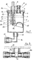
- the device for maintaining constant the oil level in an internal combustion engine which constitutes the subject of the present invention, comprises a constant level reservoir generally indicated with the reference numeral 1 which can be positioned with means which will be described hereinbelow, at a level which can be predetermined.
- the constant level reservoir 1 has a body 2 preferably of cylindrical shape which is closed at the top by a cover 3 which is sealed by the fitting of a seal 4.
- the cover 3 defines the seat for the introduction of a unidirectional breather valve, generally indicated with the reference numeral 5, which has a body 6 defining within it a through passage 7 controlled by a ball 8 which is held in place only by gravity.
- a coupling 10 which is in communication, via a communication duct 11 , with a reserve reservoir 12 which must be positioned at a higher level than the constant level reservoir 1.
- a tap 13 In the duct 11 is provided a tap 13.
- the constant level reservoir 1 is provided in its lower part with a discharge connection 15 in which is fitted an elbow connector 16 provided with a clamping nut 17 for the connection, by means of a connection duct 18, to a T-connector 19, connected as will be clarified better below, to the bottom of the oil sump 20 of the engine in such a way as to allow free communication between the interior of the constant level reservoir 10 and the oil sump so that the level of oil within the sump is maintained automatically at the level imposed by the oil in the constant level reservoir by the principal of communicating vessels.
- float valve means within the constant level reservoir 1 there act float valve means, generally indicated with the reference numeral 21 , which in practice control the passage of oil from the communication duct 11.
- the float valve 21 comprises a cylindrical body 22 the upper part of which is connected to the connector 10 and which defines a valve shutter seat 23 within which act closure balls 24 which rest on the bottom of the seat to block communication with the commurd- cation duct 11.
- a valve shutter seat 23 within which act closure balls 24 which rest on the bottom of the seat to block communication with the commurd- cation duct 11.
- an oil escape passage 30 leading tc the interior of the constant level reservoir 1 , which joins with discharge holes 31 which advantageously extend radially with respect to the oil introduction channel itself.
- actuating rod 32 which at the top is able to act by contact against the valve obturator balls 24 to open the communication and consequently allow the ingress of oil to the interior of the reservoir 1.
- the actuating rod 32 is in contact at its lower end with the cam end 33 of a lever 34 pivoted near the cam axis and having, at its end opposite the cam end, a floating part which, advantageously, is constituted by a bell 35.
- the bell 35 when the oil level in the reservoir 1 falls below a pre- determined value, itself moves downwardly by the pivoting of the lever 34 and causes, by means of its cam end 33, the actuating rod 32 to rise with consequent raising of the balls 24 which open communication therefore allowing ingress of oil into the reservoir until the desired level conditions have been regained.
- the said T-coupling 19 has a first lateral- arm 19a which, as previously indicated, is connected to the connection duct 18 which puts it into communication with the interior of the constant level reservoir 1; opposite the first arm 19a there is provided a second anm 19b from which extends a discharge duct 40 which, in conditions of use of the engine, can be fixed at 41 at the upper part of the oil sump to prevent the escape of oil.
- the tap 13 is operated to close the communication duct 11 to prevent new oil being introduced into the interior of the engine sump.
- the discharge duct 40 can also possibly be utilised to effect introduction of oil to the interior of the sump by applying to it an oil pump or other similar device.
- FIG. 4 Another important characteristic of the invention is constituted by the fact that the fitting of the device is extremely simple.
- the support device illustrated in Figure 4 is utilised, which has a substantially U-shape bracket, generally indicated 5C, which has an upper arm 5 1 and a lower arm 52 which are disposed to lie substantially horizontally and which are joined together by a vertical connection section indicated 53.
- the connection section 53 has a pair of clamping holes 54 which can be engaged by bolts which allow the connection of the bracket 5 0 at a pre-determined level on the vertical arm 60 of a bracket 61 which has a horizontal arm 62 which is provided with elongate slots 63 which can be engaged by clamping bolts normally provided in the oil sump fl ange.
- the U-bracket 50 has, on its arm 51, a through hole 55 where the coupling 10 can be advantageously lodged; adjacent the through hole 55 there is provided a cut-out 56 where a breather valve 5 can be lodged.
- the lower arm 5 2 has a deep recess 57 which is advantageously connectable to the discharge coupling 15 of the constant level reservoir 1, thus having the possibility of firmly retaining the reservoir itself.
- advantageously the constant level reservoir 1 as well as the reserve reservoir 12 can be made in optically transparent material in such a way as to allow a precise and rapid visual check of the oil level from the outside.
- the bell float effects closure of the communication and prevents further oil from being introduced into the constant level reservoir 1.
- the oil level in the interior of the oil sump therefore remains always regulated at a determined value with the result that when the motor is stopped the level achieves a certain value, indicated A, whilst while the engine is in motion, the level falls to an optimum level indicated B.
Landscapes
- Engineering & Computer Science (AREA)
- General Engineering & Computer Science (AREA)
- Mechanical Engineering (AREA)
- Physics & Mathematics (AREA)
- General Physics & Mathematics (AREA)
- Automation & Control Theory (AREA)
- Lubrication Details And Ventilation Of Internal Combustion Engines (AREA)
- Output Control And Ontrol Of Special Type Engine (AREA)
- Metal Extraction Processes (AREA)
- Level Indicators Using A Float (AREA)
- Sampling And Sample Adjustment (AREA)
Applications Claiming Priority (2)
| Application Number | Priority Date | Filing Date | Title |
|---|---|---|---|
| IT2088484 | 1984-05-11 | ||
| IT8420884A IT1185770B (it) | 1984-05-11 | 1984-05-11 | Dispositivo a vasi comunicanti per garantire il livello costatno dell'olio in un motore |
Publications (3)
| Publication Number | Publication Date |
|---|---|
| EP0161225A2 true EP0161225A2 (fr) | 1985-11-13 |
| EP0161225A3 EP0161225A3 (en) | 1987-01-07 |
| EP0161225B1 EP0161225B1 (fr) | 1990-02-07 |
Family
ID=11173529
Family Applications (1)
| Application Number | Title | Priority Date | Filing Date |
|---|---|---|---|
| EP85830109A Expired EP0161225B1 (fr) | 1984-05-11 | 1985-05-08 | Dispositif pour maintenir un niveau d'huile constant |
Country Status (8)
| Country | Link |
|---|---|
| US (1) | US4603666A (fr) |
| EP (1) | EP0161225B1 (fr) |
| JP (1) | JPS60256510A (fr) |
| AT (1) | ATE50317T1 (fr) |
| DE (1) | DE3575970D1 (fr) |
| ES (1) | ES286593Y (fr) |
| IT (1) | IT1185770B (fr) |
| TR (1) | TR22923A (fr) |
Cited By (3)
| Publication number | Priority date | Publication date | Assignee | Title |
|---|---|---|---|---|
| GB2258907A (en) * | 1991-08-09 | 1993-02-24 | Gilbert Layzell | An oil feed device |
| GB2309765A (en) * | 1996-02-01 | 1997-08-06 | William John Roberts | Float/gravity operated valve |
| CN112228544A (zh) * | 2020-11-04 | 2021-01-15 | 赤峰金剑铜业有限责任公司 | 一种改进式球磨机常规齿轮润滑系统 |
Families Citing this family (11)
| Publication number | Priority date | Publication date | Assignee | Title |
|---|---|---|---|---|
| US4741304A (en) * | 1986-03-17 | 1988-05-03 | Martin Charles E | Electronic engine oil dispenser |
| US4750456A (en) * | 1987-07-31 | 1988-06-14 | Ladrach Paul E | Automatic oil level maintenance system |
| US5303682A (en) * | 1991-10-17 | 1994-04-19 | Brunswick Corporation | Cylinder bore liner and method of making the same |
| US5425432A (en) * | 1994-02-25 | 1995-06-20 | Hurner; Erwin E. | Oil addition device |
| JP3271037B2 (ja) * | 1994-05-26 | 2002-04-02 | 日石三菱株式会社 | 内燃機関用潤滑油の補給方法及び装置 |
| DE19528933A1 (de) * | 1995-08-07 | 1997-02-13 | Intermodul Gmbh | Vorrichtung zur Regelung des Ölstandes in der Kurbelwanne eines Verbrennungsmotors |
| US20080318511A1 (en) * | 2007-06-20 | 2008-12-25 | Becker Thomas V | Ceiling wall and floor register assembly |
| US20110056452A1 (en) * | 2009-09-04 | 2011-03-10 | International Truck Intellectual Property Company, Llc | Gravity-Activated Valve For Use In Supplying An Uninterrupted Supply Of Fluid |
| JP5432104B2 (ja) * | 2010-09-28 | 2014-03-05 | 富士重工業株式会社 | 変速機油路構造 |
| CN112965539A (zh) * | 2021-02-24 | 2021-06-15 | 徐逸萍 | 一种用于数控机床的机油箱液位保持装置 |
| US12454900B2 (en) * | 2024-03-26 | 2025-10-28 | JohnDow Industries, Inc. | Fluid evacuation collection vessel assemblies and fluid evacuation systems and methods |
Family Cites Families (11)
| Publication number | Priority date | Publication date | Assignee | Title |
|---|---|---|---|---|
| FR3079E (fr) * | 1902-06-06 | 1904-08-30 | Jules Boucly | Moteur à quatre temps à circulation d'eau et sièges de soupapes interchangeables et système de carter à graisseur automatique (système boucly) |
| FR541349A (fr) * | 1921-09-20 | 1922-07-26 | Dispositif de graissage automatique et à débit proportionnel pour moteurs à pression variable dans le carter | |
| US1632215A (en) * | 1921-12-24 | 1927-06-14 | Robert E Borbeck | Oil-level regulator |
| US1972962A (en) * | 1933-05-08 | 1934-09-11 | Weber Max | Constant level apparatus |
| US2283303A (en) * | 1941-08-26 | 1942-05-19 | Stewart B Whitlock | Oil level regulator |
| US2586104A (en) * | 1949-06-01 | 1952-02-19 | Elmer D Smyser | Automatic oiler |
| US2689628A (en) * | 1950-07-26 | 1954-09-21 | Charles F Schott | Automatic oil level control device |
| DE1498314B2 (de) * | 1965-11-06 | 1970-04-16 | Daimler-Benz AG, 7000 Stuttgart-Untertür kheim | Vorrichtung zur Messung des Ölverbrauchs |
| US3458011A (en) * | 1967-12-22 | 1969-07-29 | Gen Electric | Lubrication - supply system utilizing blow-by gases to maintain a generally constant oil level |
| JPS55153811A (en) * | 1979-05-16 | 1980-12-01 | Fuji Heavy Ind Ltd | Lubricating oil alarm for engine |
| FR2522066B1 (fr) * | 1982-02-25 | 1985-10-31 | Craf | Dispositif de maintien du niveau d'huile dans un moteur |
-
1984
- 1984-05-11 IT IT8420884A patent/IT1185770B/it active
-
1985
- 1985-05-06 US US06/731,060 patent/US4603666A/en not_active Expired - Fee Related
- 1985-05-08 DE DE8585830109T patent/DE3575970D1/de not_active Expired - Lifetime
- 1985-05-08 ES ES1985286593U patent/ES286593Y/es not_active Expired
- 1985-05-08 AT AT85830109T patent/ATE50317T1/de not_active IP Right Cessation
- 1985-05-08 EP EP85830109A patent/EP0161225B1/fr not_active Expired
- 1985-05-10 TR TR23649/85A patent/TR22923A/xx unknown
- 1985-05-11 JP JP60098919A patent/JPS60256510A/ja active Pending
Cited By (6)
| Publication number | Priority date | Publication date | Assignee | Title |
|---|---|---|---|---|
| GB2258907A (en) * | 1991-08-09 | 1993-02-24 | Gilbert Layzell | An oil feed device |
| GB2258907B (en) * | 1991-08-09 | 1995-03-29 | Gilbert Layzell | An oil feed device |
| GB2309765A (en) * | 1996-02-01 | 1997-08-06 | William John Roberts | Float/gravity operated valve |
| GB2309765B (en) * | 1996-02-01 | 2000-03-22 | William John Roberts | Liquid storage systems and valves for use therein |
| CN112228544A (zh) * | 2020-11-04 | 2021-01-15 | 赤峰金剑铜业有限责任公司 | 一种改进式球磨机常规齿轮润滑系统 |
| CN112228544B (zh) * | 2020-11-04 | 2022-12-27 | 赤峰金通铜业有限公司 | 一种改进式球磨机常规齿轮润滑系统 |
Also Published As
| Publication number | Publication date |
|---|---|
| JPS60256510A (ja) | 1985-12-18 |
| IT8420884A0 (it) | 1984-05-11 |
| IT1185770B (it) | 1987-11-18 |
| TR22923A (tr) | 1988-11-24 |
| ES286593U (es) | 1985-11-16 |
| EP0161225A3 (en) | 1987-01-07 |
| US4603666A (en) | 1986-08-05 |
| EP0161225B1 (fr) | 1990-02-07 |
| DE3575970D1 (de) | 1990-03-15 |
| ATE50317T1 (de) | 1990-02-15 |
| ES286593Y (es) | 1986-06-01 |
Similar Documents
| Publication | Publication Date | Title |
|---|---|---|
| EP0161225A2 (fr) | Dispositif pour maintenir un niveau d'huile constant | |
| US5103877A (en) | Vapor-liquid separator for evaporative emissions control system | |
| AU608506B2 (en) | Tank constructions for containing fuel, and water separators for fuel feed systems | |
| US3447636A (en) | Automatic oil exchanging system | |
| US4796777A (en) | Vented fuel tank cap and valve assembly | |
| US6206056B1 (en) | Fill limiter for a liquid storage tank | |
| US6708713B1 (en) | Fill limit control valve assembly having a liquid fuel trap | |
| US5010915A (en) | Two stage automatic shut off valve | |
| US4901754A (en) | Valve improvements | |
| EP0575856B1 (fr) | Construction d'une vanne de trop plein | |
| US3685655A (en) | Automatic water draining device for fuel filter | |
| DE3016434C2 (de) | Ausgleichsbehälter | |
| US2886056A (en) | Valve assembly | |
| US20030221746A1 (en) | Filling device for oil level regulation on oil pans in engines and transmissions | |
| US5934306A (en) | Fuel tank for motor vehicles | |
| US4741358A (en) | Liquid level control float valve | |
| US4724926A (en) | Oil dispenser for internal combustion engines | |
| US3242937A (en) | Safety valve for gasoline tanks having plural control means | |
| US5285533A (en) | Anti-leakage apparatus for containers for liquid | |
| US6314989B1 (en) | Device for draining of oil in a component of a vehicle | |
| GB2309767A (en) | Damped float valve | |
| US6474374B1 (en) | Device for filling a reservoir of a fuel supply module and fuel supply module including said device | |
| US5425432A (en) | Oil addition device | |
| US2599426A (en) | Automatic valve | |
| KR100387716B1 (ko) | 오일팬내 엔진오일의 유면높이 조절장치 |
Legal Events
| Date | Code | Title | Description |
|---|---|---|---|
| PUAI | Public reference made under article 153(3) epc to a published international application that has entered the european phase |
Free format text: ORIGINAL CODE: 0009012 |
|
| AK | Designated contracting states |
Designated state(s): AT BE CH DE FR GB LI NL SE |
|
| PUAL | Search report despatched |
Free format text: ORIGINAL CODE: 0009013 |
|
| AK | Designated contracting states |
Kind code of ref document: A3 Designated state(s): AT BE CH DE FR GB LI NL SE |
|
| 17P | Request for examination filed |
Effective date: 19870519 |
|
| 17Q | First examination report despatched |
Effective date: 19880309 |
|
| GRAA | (expected) grant |
Free format text: ORIGINAL CODE: 0009210 |
|
| AK | Designated contracting states |
Kind code of ref document: B1 Designated state(s): AT BE CH DE FR GB LI NL SE |
|
| PG25 | Lapsed in a contracting state [announced via postgrant information from national office to epo] |
Ref country code: SE Effective date: 19900207 Ref country code: NL Effective date: 19900207 Ref country code: LI Effective date: 19900207 Ref country code: FR Effective date: 19900207 Ref country code: CH Effective date: 19900207 Ref country code: BE Effective date: 19900207 Ref country code: AT Effective date: 19900207 |
|
| REF | Corresponds to: |
Ref document number: 50317 Country of ref document: AT Date of ref document: 19900215 Kind code of ref document: T |
|
| REF | Corresponds to: |
Ref document number: 3575970 Country of ref document: DE Date of ref document: 19900315 |
|
| PG25 | Lapsed in a contracting state [announced via postgrant information from national office to epo] |
Ref country code: GB Effective date: 19900508 |
|
| REG | Reference to a national code |
Ref country code: CH Ref legal event code: PL |
|
| EN | Fr: translation not filed | ||
| NLV1 | Nl: lapsed or annulled due to failure to fulfill the requirements of art. 29p and 29m of the patents act | ||
| PLBE | No opposition filed within time limit |
Free format text: ORIGINAL CODE: 0009261 |
|
| STAA | Information on the status of an ep patent application or granted ep patent |
Free format text: STATUS: NO OPPOSITION FILED WITHIN TIME LIMIT |
|
| GBPC | Gb: european patent ceased through non-payment of renewal fee | ||
| 26N | No opposition filed | ||
| PG25 | Lapsed in a contracting state [announced via postgrant information from national office to epo] |
Ref country code: DE Effective date: 19910201 |