EP0161321A1 - Procede d'usinage pour machine-outil - Google Patents
Procede d'usinage pour machine-outil Download PDFInfo
- Publication number
- EP0161321A1 EP0161321A1 EP84903990A EP84903990A EP0161321A1 EP 0161321 A1 EP0161321 A1 EP 0161321A1 EP 84903990 A EP84903990 A EP 84903990A EP 84903990 A EP84903990 A EP 84903990A EP 0161321 A1 EP0161321 A1 EP 0161321A1
- Authority
- EP
- European Patent Office
- Prior art keywords
- tool
- point
- path
- machining
- cutting
- Prior art date
- Legal status (The legal status is an assumption and is not a legal conclusion. Google has not performed a legal analysis and makes no representation as to the accuracy of the status listed.)
- Granted
Links
Images



Classifications
-
- G—PHYSICS
- G05—CONTROLLING; REGULATING
- G05B—CONTROL OR REGULATING SYSTEMS IN GENERAL; FUNCTIONAL ELEMENTS OF SUCH SYSTEMS; MONITORING OR TESTING ARRANGEMENTS FOR SUCH SYSTEMS OR ELEMENTS
- G05B19/00—Program-control systems
- G05B19/02—Program-control systems electric
- G05B19/18—Numerical control [NC], i.e. automatically operating machines, in particular machine tools, e.g. in a manufacturing environment, so as to execute positioning, movement or co-ordinated operations by means of program data in numerical form
- G05B19/41—Numerical control [NC], i.e. automatically operating machines, in particular machine tools, e.g. in a manufacturing environment, so as to execute positioning, movement or co-ordinated operations by means of program data in numerical form characterised by interpolation, e.g. the computation of intermediate points between programmed end points to define the path to be followed and the rate of travel along that path
-
- G—PHYSICS
- G05—CONTROLLING; REGULATING
- G05B—CONTROL OR REGULATING SYSTEMS IN GENERAL; FUNCTIONAL ELEMENTS OF SUCH SYSTEMS; MONITORING OR TESTING ARRANGEMENTS FOR SUCH SYSTEMS OR ELEMENTS
- G05B2219/00—Program-control systems
- G05B2219/30—Nc systems
- G05B2219/49—Nc machine tool, till multiple
- G05B2219/49381—Raster, line servo, area machining, cutting, facing
-
- G—PHYSICS
- G05—CONTROLLING; REGULATING
- G05B—CONTROL OR REGULATING SYSTEMS IN GENERAL; FUNCTIONAL ELEMENTS OF SUCH SYSTEMS; MONITORING OR TESTING ARRANGEMENTS FOR SUCH SYSTEMS OR ELEMENTS
- G05B2219/00—Program-control systems
- G05B2219/30—Nc systems
- G05B2219/49—Nc machine tool, till multiple
- G05B2219/49385—Using pick feed when machining a surface
Definitions
- This invention relates to a machining method performed by a machine tool having axes of rotation for subjecting a workpiece to desired machining by moving a tool relative to a workpiece along a cutting path from a predetermined direction to perform machining, positioning the tool at a machining starting point on the next cutting path after the completion of machining along the abovementioned cutting path, thereafter moving the tool relative to the workiece along the next cutting path from the predetermined direction to perform machining, and thereafter repeating the foregoing operations. More particularly, the invention relates to a machining tool machining method whereby a path from a machining end point to a machining starting point can be created automatically and, moreover, whereby the tool will not be allowed to strike the workpiece when the tool is moved.
- a workpiece is subjected to desired machining by moving a tool TL at a cutting velocity from left to right along a predetermined cutting path PT1 on a workpiece WK to perform machining, moving the tool in a rapid-traverse mode from an end point Pe to a cutting starting point Ps on the next cutting path PT2 at the conclusion of machining along the abovementioned path, then moving the tool at the cutting velocity along the next cutting path while maintaining the abovementioned cutting direction, and thereafter repeating this unidirectional cutting operation.
- machining is carried out in such a manner that the central axis (the one-dot chain line in Fig. 1) of the tool TL is directed normal to the workpiece WK or oriented in a direction having a fixed angle of inclination with respect to the direction of the normal line at all times. Consequently, by way of example, the machine tool is arranged to rotate the tool while the tool is being moved along orthogonal axes in three dimensions, whereby machining can be performed while the direction of the central axis of the tool is brought into agreement with the direction of the normal line to the workpiece at all times.
- NC data specifying the path include position data (position vectors) for specifying the position of the tool nose, and tool central axis direction data (positions along B and C axes or tool central axis vector) for specifying the direction of the tool central axis.
- position data position vectors
- tool central axis direction data positions along B and C axes or tool central axis vector
- B and C axes are vertical and horizontal axes of rotation.
- an object of the present invention is to provide a machine tool machining method whereby a pick-feed path that will not cause a tool to strike a workpiece when a pick-feed is performed can be decided in a simple manner.
- Another object of the present invention is to provide a machine tool machining method whereby NC data for machining a curved surface, which data will not cause a tool to strike a workpiece when a pick-feed is performed, can be created automatically, and moreover whereby a curved surface can be machined by using these NC data.
- Still another object of the present invention is to provide a machine tool machining method whereby a pick-feed command or a command for creating a pick-feed path is inserted into an NC program in advance, a pick-feed path that will not cause a tool to strike a workpiece is obtained automatically in response to the command, and the tool is moved along the pick-feed path obtained.
- the present invention provides a method of machining a curved surface performed by unidirectional cutting, which method includes automatically creating a pick-feed path that will not cause a tool to strike a workpiece when a pick-feed is performed, pick-feeding the tool along the pick-feed path, and thereafter performing cutting.
- a tool retraction quantity 1 for retracting a tool in the direction of the central axis of the tool from the cutting path end point Pe, and a clearance plane containing a path along which the tool is moved toward the next cutting starting point Ps, are specified in advance, and there are obtained coordinate values of a point Pa distanced from the cutting path end point Pe by the tool retraction quantity t in the direction of the central axis of the tool at the cutting path end point, coordinate values of the foot Pb of a perpendicular dropped from the point Pa to the clearance plane, coordinate values of a point Pd distanced from the cutting path starting point Ps by the tool retraction quantity l in the direction of the central axis of the tool at the cutting path starting point, and coordinate values of the foot Pc of a perpendicular dropped from the point Pd to the clearance plane.
- the path Pe ⁇ Pa ⁇ Pb ⁇ Pc ⁇ Pd ⁇ Ps will serve as the pick-feed path. Accordingly, after the completion of cutting along one path, a pick-feed path is obtained through the foregoing technique, thereafter the tool is moved along the pick-feed path and positioned at the next cutting starting point Ps, and the tool is then moved along the next cutting path to perform machining. According to this method, a path for positioning the tool from the cutting path end point Pe to the cutting path starting point Ps without the tool striking the workpiece can be created automatically, and a pick-feed can then be performed along the path.
- Fig. 1 is a view for describing a tool path for a case where a curved surface is machined by repeating pick-feed and back-and-forth cutting
- Fig. 2 is a view for describing the trajectory of a tool nose for a case where a machine tool includes axes of rotation
- Fig. 3 is a view for describing the general features of the present invention
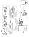
- Fig. 4 is a block diagram of an embodiment of the present invention
- Fig. 5 is a block diagram of another embodiment of the present invention
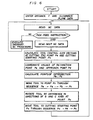
- Figs. 6 and 7 are flowcharts of processing for a case where the circuits of Figs. 4 and 5 are constituted by a microcomputer, respectively.
- Fig. 3 is a view for describing the general features of the present invention.
- a workpiece is subjected to desired machining by moving a tool TL relative to a workpiece along a cutting path PTl from one direction to perform machining, positioning the tool at a machining starting point Ps on the next cutting path PT2 after the completion of machining along the abovementioned cutting path (this operation being referred to as a "pick-feed"), thereafter moving the tool relative to the workiece along the next cutting path from the aforementioned direction to perform machining, and subsequently repeating the foregoing operations.
- the pick-feed path is obtained by specifying beforehand a tool retraction quantity 1 for retracting the tool from the cutting path end point Pe in the direction of the central axis of the tool at the cutting path end point, and a clearance plane CPL containing a path PFP along which the tool is moved toward the next cutting starting point Ps, and performing processing, now to be described, by using these data.
- a pick-feed path is obtained through the foregoing technique, then the tool is moved along the pick-feed path and positioned at the next cutting starting point Ps, and the tool is thereafter moved along the next cutting path to perform machining.
- Fig. 4 is a block diagram of an embodiment of the present invention.
- An NC tape or memory (assumed to be an NC tape hereafter) 101 stores NC data.
- the NC data are so arranged that the tool TL is made to perform cutting in the direction of the arrow up to the end point Pe along the first machining path PT1 of Fig. 3, next is pick-fed from the end point Pe to the machining starting point Ps on the second machining path PT2, then is made to perform cutting in the direction of the arrow along the second machining path, and therafter is made to repeat this unidirectional cutting operation.
- Each of the paths PT1, PT2 is approximated by minute polygonal lines, and a pick-feed is indicated by an M-function instruction M ⁇ (where ⁇ is a two-digit numerical value).
- An NC data reader 102 reads the NC data from the NC tape 101 one block at a time and stores the data in an input memory 103.
- a numerical control unit 104 decodes the NC data stored in the input memory 103. If the NC data are path data, then these data are delivered to a pulse distributor 105. If an item of NC data is an M-, S- or T- function instruction to be delivered to the machine side, then the instruction is applied to a machine tool 107 through a magnetics circuit 106. If an item of data is a pick-feed instruction M ⁇ ⁇ , then the NC data reader 102 is made to read the next block of NC data (data indicative of the starting point of the next machining path).
- the numerical control unit 104 finds incremental values Xi, Yi, Zi, Bi, Ci along the respective axes (rectangular coordinates axes X, Y, Z, vertical axis of rotation B and horizontal axis of rotation C).
- the pulse distributor 105 On the basis of the input data, the pulse distributor 105 performs a simultaneous five-axis pulse distribution calculation to generate distributed pulses Xp, Yp, Zp, Bp, Cp. These are delivered to servo circuits (not shown) for the respective axes to transport the tool along the cutting path.
- the numerical control unit 104 in accordance with the following formulae, updates the present position X a , Y a , Za, Ba, Ca in a present position memory 108 every ⁇ T sec:
- the numerical control unit 104 updates remaining travelling distances X , Y r , Z , Br, Cr (the initial / values of which are the incremental values X i , Y i , Z i , Bi, Ci respectively) every ⁇ T sec, X , Y r , Z r , Bi, Ci having been stored in a remaining travelling distance memory 109:
- pulse distribution processing or other processing is performed on the basis of the next block of NC data preread by the NC data reader 102.
- the numerical control unit 104 immediately reads the next block of NC data and stores the data in the input memory 103.
- the NC data commanded following the pick-feed instruction are the position data Xn, Yn, Zn, Bn, Cn indicative of the machining starting point Ps of the second machining path PT2. These data are stored in the input memory 103.
- a tool central axis vector arithmetic unit 110 responds to a calculation start signal from the numerical control unit 104 by obtaining, and storing in a vector memory 111, a tool central axis vector Ve (ie, je, ke) at the present position (the machining end point Pe on the first machining path PT1), and a tool central axis vector Vs (is, js, ks) at the machining starting point Ps on the second machining path PT2.
- the tool central axis vector arithmetic unit 110 is capable of obtaining the tool central axis vectors Ve, Vs from Eqs. (6a) through 6(c) by using the positions (Ba, Bn) and (Ca, Cn) along the directions of vertical and horizontal rotation of the machining end point Pe and machining starting point Ps, which are stored in the present position memory 108 and input memory 103, respectively.
- a point arithmetic unit 112 obtains the coordinate values of a retraction point Pa distanced from the cutting path end point Pe by I in the direction of the central axis of the tool at the end point, and the coordinate values of an approach point Pd distanced from the cutting path starting point Ps by l in the direction of the central axis of the tool at the starting point.
- the distance 1 and a plane equation of the clearance plane CPL are fed into a parameter memory 114 from a manual data input unit (MDI unit) 113 or the like.
- the point arithmetic unit 112 is capable of obtaining three-dimensional coordinate values of the retraction point Pa and of the approach point Pd from Eqs. (8a), (8b). These calculated coordinate values are applied as inputs to the numerical control unit 104 and an intersection arithmetic unit 115, which is the next stage.
- the intersection arithmetic unit 115 calculates the coordinate values of the foots Pb, Pc of perpendiculars dropped from the points Pa, Pd to the clearance plane CP.
- h represent the distance to the foot Q (position vector Q) of a perpendicular dropped from a point P (position vector P) to a clearance plane expressed by Eq. (7)
- N is the vector, expressed as (i, j, k), of the normal to the clearance plane, and h includes the sign.
- the coordinate values of the foot Q of the perpendicular will be specified if h in Eq. (9a) is found.
- R (Rx, Ry, Rz) be one point on the clearance plane, the following will hold: If the direction of the plane as seen from the point P (Pc, Py, Pz) and the direction of N coincide, h will be positive; if not, h will be negative.
- the intersection arithmetic unit 115 is capable of deriving the coordinate values of the foots Pb, Pc of perpendiculars dropped on the clearance plane PL based on the retraction point Pa, the approach point Pd and the plane equation of the clearance plane, by using Eqs. (9a) and (9e). These calculated coordinate values are applied to the numerical control unit 104.
- the numerical control unit 104 calculates the incremental values Xi, Yi, Zi along the respective three-dimensional axes from the machining end point Pe to the retraction point Pa from the equations by using the three-dimensional coordinate values (XA, YA, ZA) of the retraction point Pa. Thereafter, the calculations of Eqs. (la) - (lc), (2a) - (2c) are performed as described above to obtain ⁇ X, ⁇ Y, pZ, and these are applied to the pulse distributor 105 every ⁇ T seconds. The numerical control unit 104 performs the calculations of Eqs. (3a) - (3c), (4a) - (4c) every ⁇ T seconds.
- the numerical control unit 104 uses the three-dimensional coordinate values (XB, YB, ZB) of the foot (point of intersection ) Pb of the perpendicular to calculate, in similar fashion, the incremental values Xi, Yi, Zi along the respective three-dimensional axes from the retraction point Pa to the point of intersection Pb from the equations Thereafter, processing is executed which is exactly the same as that performed when the tool was moved from Pe to Pa.
- the numerical control unit 104 uses the three-dimensional coordinate values (Xc, Yc, Zc) of the foot (point of intersection ) Pc of the perpendicular to calculate the incremental values Xi, Yi, Zi from the point of intersection Pb to the point of intersection Pc from the equations Thereafter, processing is executed which is exactly the same as that performed when the tool was moved from Pe to Pa.
- the numerical control unit 104 performs the operations indicated by to calculate incremental values in the directions of vertical and horizontal rotation. Thereafter, the calculations of Eqs. (ld) - (le), (2d) - (2e) are performed to obtain ⁇ B, ⁇ C, and these are applied as inputs to the pulse distributor 105 every a T seconds.
- the numerical control unit 104 performs the calculations of Eqs. (3d) - (3e), (4d) - (4e) every AT seconds.
- the numerical control unit 104 calculates the incremental values Xi, Yi, Zi from the point of intersection Pc to the approach point Pd from the equations by using the three-dimensional coordinate values (XD, YD, ZD) of the approach point Pd. Thereafter, processing is executed which is exactly the same as that performed when the tool was moved from Pe to Pa.
- the numerical control unit When the condition is established, namely when the tool arrives at the approach point Pd, the numerical control unit performs the operations indicated by to calculate incremental values Xi, Yi, Zi along the respective three-dimensional axes from the approach point Pd to the machining starting point Ps. Then, in a similar manner, d X, ⁇ Y, ⁇ Z are found and applied as inputs to the pulse distributor 105 every ⁇ T seconds.
- the NC data reader 102 is caused to read the next block of NC data.
- the second path is subsequently machined by moving the tool along the second machining path PT2 on the basis of the NC data.
- the curved surface will eventually be machined if the foregoing operations are repeated.
- the tool central axis vector V (i, j, k) may be given instead of B and C.
- the tool central axis vector arithmetic unit 110 is unnecessary [i.e., it is unnecessary to perform the calculations of Eqs. (6a) - (6c)].
- a pick-feed instruction is inserted into an NC program in advance, a pick-feed path is obtained automatically when the pick-feed instruction is read from the NC tape after the completion of machining along the first machining path, the tool is moved along the pick-feed path, and machining is subsequently performed along the second machining path.
- the present invention is not limited to such an arrangement.
- it can be arranged to enter data specifying a curved surface and data indicating a pick-feed, create NC data specifying a cutting path by using the curved surface data, obtain an NC tape by creating NC data for a pick-feed path through the above-described method on the basis of the data indicating the pick-feed, and machining the curved surface by loading the NC tape into an NC unit.
- NC data comprising NC data for specifying a cutting path, and a pick-feed instructions
- feed the data into an NC tape creating unit obtain a pick-feed path through the above-described method based on a pick-feed instruction to create NC data specifying the pick-feed path, substitute these NC data for the pick-feed instruction thereby to recreate an NC tape containing pick-feed path data in place of the pick-feed instruction, and machine the curved surface by loading the NC tape into an NC unit.
- Fig. 5 is a block diagram of such an embodiment of the present invention. Portions similar to those shown in Fig. 4 are designated by like reference symbols.
- Stored in the NC tape or memory 101 are a number of NC data comprising NC data specifying a cutting path, and pick-feed instructions.
- the data specifying the paths need not necessarily be NC data but can be position data specifying the end points of very small straight lines when a curve is expressed as a polygonal approximation in the form of very small straight lines, as well as data specifying the direction of the central axis of the tool.
- the NC data reader 102 reads NC data from the NC tape 101 one block at a time and stores the data in the input memory 103.
- the input memory is designed to be capable of storing two blocks of path data.
- An NC tape creating processor 201 determines whether the present block of NC data stored in the input memory 103 is a pick-feed instruction. If it is not, the NC data are delivered as is to an NC data output unit (paper tape puncher, magnetic tape unit, etc.) 202, after which the NC data reader 102 is made to read the next block of NC data.
- an NC data output unit paper tape puncher, magnetic tape unit, etc.
- the NC tape creating processor 201 causes the NC data reader 102 to read the next block of NC data, namely the three-dimensional position data Xn, Yn, Zn indicative of the machining starting point Ps on the second machining path, and the position data Bn, Cn in the directions of vertical and horizontal rotation, and to store these data in the input memory 103.
- the three-dimensional position data Xa, Ya, Za indicative of the machining end point Pe on the first machining path and the position data Ba, Ca in the directions of vertical and horizontal rotation have also been stored in the input memory 103.
- the tool central axis vector arithmetic unit 110 obtains the tool central axis vector Ve (ie, je, ke) at the present position (machining end point Pe on the first machining path PT1) from Eqs. (6a) - (6c) by using the vertical rotation position Ba and horizontal rotation position Ca stored in the input memory 103, obtains the tool central axis vector Vs (is, js, ks) at the machining starting point Ps from Eqs. (6a) - (6c) by using the vertical rotation position Bn and horizontal rotation position Cn at the machining starting point Ps stored in the input memory 103, and stores these vectors in the vector memory 111.
- the point arithmetic unit 112 and intersection arithmetic unit 115 then perform the calculations described above with relation to Fig. 4 to calculate the coordinate values of the retraction point Pa, points of intersection Pb, Pc and approach point Pd. These are applied as inputs to the NC tape creating processor 201. It should be noted that data specifying the distance 3. and the clearance plane are assumed to have already been entered from the MDI unit 113 or NC tape 101 and stored in the parameter memory 114.
- the NC tape creating processor 201 When the three-dimensional coordinate values of the retraction point Pa, the points of intersection Pb, Pc and the approach poind Pd are applied, the NC tape creating processor 201 first creates positioning data for effecting positioning from the cutting end point Pe to the retraction point Pa. These data are delivered to the NC data output unit 202. Next, the NC tape creating processor 201 creates positioning data for effecting positioning from the retraction point Pa to the point of intersection Pb. These data are delivered to the NC data output unit 202. Thereafter, the NC tape creating processor 201 creates positioning data for effecting positioning from the point of intersection Pb to the point of intersection Pc. These data likewise are delivered to the NC data output unit 202.
- the NC tape creating processor 201 then rotates the tool in the vertical and horizontal directions at the point of intersection Pc, creates rotation direction positioning data for bringing the tool central axis vector into coincidence therewith at the machining starting point Ps, and delivers these data to the NC data output unit 202.
- the NC tape creating processor 201 creates positioning data for effecting positioning from the point of intersection Pc to the approach point Pd and delivers these data to the NC data output unit 202. Finally, positioning data is created for effecting positioning from the approach point Pd to the cutting starting point Ps, and these data are delivered to the NC data output unit 202.
- the next block of NC data is read by the NC data reader 102, on the basis of which NC data the foregoing processing is repeated. In this manner, an NC tape 203 for creating the curved surface is created. Note that the NC data are assumed to be created in the form of absolute data.
- NC data stored on the NC tape 203 created through the foregoing processing are read by an NC unit 204, which proceeds to execute NC processing based on the read NC data. More specifically, a pick-feed is carried out after cutting is performed along the first machining path, cutting is implemented along the second machining path after the pick-feed, and the foregoing operations are subsequently repeated to machine the curved surface.
- circuitry enclosed by the dashed line in Figs. 4 and 5 can be constituted by a microcomputer. In such case the flowcharts of the processing executed by the processors would be as shown in Figs. 6 and 7, respectively.
- a pick-feed path which will not cause the tool to strike the workpiece can be created automatically even if the path is not specified by NC data, thereby simplifying programming.
- the path can be so created as to shorten the pick-feed stroke and curtail machining time.
Landscapes
- Engineering & Computer Science (AREA)
- Computing Systems (AREA)
- Theoretical Computer Science (AREA)
- Human Computer Interaction (AREA)
- Manufacturing & Machinery (AREA)
- Physics & Mathematics (AREA)
- General Physics & Mathematics (AREA)
- Automation & Control Theory (AREA)
- Numerical Control (AREA)
- Milling Processes (AREA)
Abstract
Applications Claiming Priority (2)
| Application Number | Priority Date | Filing Date | Title |
|---|---|---|---|
| JP204575/83 | 1983-10-31 | ||
| JP58204575A JPS6094255A (ja) | 1983-10-31 | 1983-10-31 | 工作機械の加工方法 |
Publications (3)
| Publication Number | Publication Date |
|---|---|
| EP0161321A1 true EP0161321A1 (fr) | 1985-11-21 |
| EP0161321A4 EP0161321A4 (fr) | 1988-01-07 |
| EP0161321B1 EP0161321B1 (fr) | 1991-01-30 |
Family
ID=16492736
Family Applications (1)
| Application Number | Title | Priority Date | Filing Date |
|---|---|---|---|
| EP84903990A Expired EP0161321B1 (fr) | 1983-10-31 | 1984-10-30 | Procede d'usinage pour machine-outil |
Country Status (5)
| Country | Link |
|---|---|
| US (1) | US4692873A (fr) |
| EP (1) | EP0161321B1 (fr) |
| JP (1) | JPS6094255A (fr) |
| DE (1) | DE3484065D1 (fr) |
| WO (1) | WO1985001909A1 (fr) |
Cited By (3)
| Publication number | Priority date | Publication date | Assignee | Title |
|---|---|---|---|---|
| EP0320182A1 (fr) | 1987-12-03 | 1989-06-14 | Dyno Nobel Inc. | Explosif en émulsion contenant un agent de réduction de la densité |
| EP0459251A1 (fr) * | 1990-05-17 | 1991-12-04 | Sony Corporation | Méthode pour générer des données définissant la trajectoire d'outil pour l'ébauchage |
| US5289383A (en) * | 1990-05-17 | 1994-02-22 | Sony Corporation | Method for establishing data defining tool path for rough machining |
Families Citing this family (7)
| Publication number | Priority date | Publication date | Assignee | Title |
|---|---|---|---|---|
| JPS6249503A (ja) * | 1985-08-29 | 1987-03-04 | Mitsubishi Electric Corp | 数値制御装置 |
| JPH069007B2 (ja) * | 1986-04-04 | 1994-02-02 | フアナツク株式会社 | 複合曲面のncデ−タ作成方法 |
| JPS6435606A (en) * | 1987-07-30 | 1989-02-06 | Fanuc Ltd | Nc data preparing system for grooving |
| JPH0760336B2 (ja) * | 1988-12-28 | 1995-06-28 | オ−クマ株式会社 | 数値制御装置 |
| US5583409A (en) * | 1992-08-31 | 1996-12-10 | Fanuc Ltd | Numerical control apparatus and method for controlling a machine |
| EP1302829B1 (fr) * | 2001-10-16 | 2008-11-26 | Fanuc Ltd | Commande numérique |
| JP7316169B2 (ja) * | 2019-09-25 | 2023-07-27 | ファナック株式会社 | 数値制御装置 |
Family Cites Families (5)
| Publication number | Priority date | Publication date | Assignee | Title |
|---|---|---|---|---|
| JPS54140279A (en) * | 1978-04-24 | 1979-10-31 | Fanuc Ltd | Profiling control system |
| JPS5627764A (en) * | 1979-08-07 | 1981-03-18 | Shin Nippon Koki Kk | Control device for copying machine tool |
| JPS6049543B2 (ja) * | 1979-10-11 | 1985-11-02 | ファナック株式会社 | 倣い制御方式 |
| JPS57194859A (en) * | 1981-05-21 | 1982-11-30 | Mitsubishi Electric Corp | Profiling controlling device |
| JPS5917606A (ja) * | 1982-07-22 | 1984-01-28 | Fanuc Ltd | 数値制御方法 |
-
1983
- 1983-10-31 JP JP58204575A patent/JPS6094255A/ja active Granted
-
1984
- 1984-10-30 US US06/752,075 patent/US4692873A/en not_active Expired - Fee Related
- 1984-10-30 EP EP84903990A patent/EP0161321B1/fr not_active Expired
- 1984-10-30 WO PCT/JP1984/000523 patent/WO1985001909A1/fr not_active Ceased
- 1984-10-30 DE DE8484903990T patent/DE3484065D1/de not_active Expired - Lifetime
Non-Patent Citations (2)
| Title |
|---|
| No relevant documents have been disclosed. * |
| See also references of WO8501909A1 * |
Cited By (3)
| Publication number | Priority date | Publication date | Assignee | Title |
|---|---|---|---|---|
| EP0320182A1 (fr) | 1987-12-03 | 1989-06-14 | Dyno Nobel Inc. | Explosif en émulsion contenant un agent de réduction de la densité |
| EP0459251A1 (fr) * | 1990-05-17 | 1991-12-04 | Sony Corporation | Méthode pour générer des données définissant la trajectoire d'outil pour l'ébauchage |
| US5289383A (en) * | 1990-05-17 | 1994-02-22 | Sony Corporation | Method for establishing data defining tool path for rough machining |
Also Published As
| Publication number | Publication date |
|---|---|
| JPH022661B2 (fr) | 1990-01-18 |
| JPS6094255A (ja) | 1985-05-27 |
| DE3484065D1 (de) | 1991-03-07 |
| US4692873A (en) | 1987-09-08 |
| EP0161321B1 (fr) | 1991-01-30 |
| EP0161321A4 (fr) | 1988-01-07 |
| WO1985001909A1 (fr) | 1985-05-09 |
Similar Documents
| Publication | Publication Date | Title |
|---|---|---|
| EP0160097B1 (fr) | Procece d'usinage de surfaces | |
| EP0046032B1 (fr) | Méthode de commande numérique | |
| EP0075022B1 (fr) | Systeme de compensation de diametre d'outil | |
| US4703415A (en) | Method of approach in area cutting | |
| US4739489A (en) | Area cutting method | |
| EP0077177B1 (fr) | Méthode et dispositif pour la commande numérique | |
| US4572998A (en) | Tool radius compensation system | |
| EP0161321B1 (fr) | Procede d'usinage pour machine-outil | |
| EP0175792B1 (fr) | Procede d'usinage de surfaces | |
| EP0166000B1 (fr) | Procede d'usinage de surfaces | |
| EP0063615A1 (fr) | Procede de commande numerique | |
| EP0144426B1 (fr) | Procede de controle d'interference d'outil | |
| US4535408A (en) | Numerical control machining method and apparatus | |
| EP0168501B1 (fr) | Procede d'usinage de surfaces | |
| EP0104542B1 (fr) | Méthode d'usinage à commande numérique | |
| US4689750A (en) | Machine tool method for deciding if a workpiece surface is concave or convex | |
| EP0314798B1 (fr) | Preparation de donnees de commande numerique pour l'usinage de surfaces incurvees | |
| EP0231388B1 (fr) | Procede d'usinage de surface | |
| US4764878A (en) | Surface cutting method | |
| WO1988006310A1 (fr) | Dispositif de programmation pour tour | |
| US5583409A (en) | Numerical control apparatus and method for controlling a machine | |
| JPH022660B2 (fr) | ||
| JPS5917606A (ja) | 数値制御方法 | |
| US4584509A (en) | Method of discriminating present position region of a machine | |
| JPH022662B2 (fr) |
Legal Events
| Date | Code | Title | Description |
|---|---|---|---|
| PUAI | Public reference made under article 153(3) epc to a published international application that has entered the european phase |
Free format text: ORIGINAL CODE: 0009012 |
|
| 17P | Request for examination filed |
Effective date: 19850710 |
|
| AK | Designated contracting states |
Designated state(s): DE FR GB |
|
| A4 | Supplementary search report drawn up and despatched |
Effective date: 19880107 |
|
| 17Q | First examination report despatched |
Effective date: 19891221 |
|
| GRAA | (expected) grant |
Free format text: ORIGINAL CODE: 0009210 |
|
| AK | Designated contracting states |
Kind code of ref document: B1 Designated state(s): DE FR GB |
|
| REF | Corresponds to: |
Ref document number: 3484065 Country of ref document: DE Date of ref document: 19910307 |
|
| ET | Fr: translation filed | ||
| PLBE | No opposition filed within time limit |
Free format text: ORIGINAL CODE: 0009261 |
|
| STAA | Information on the status of an ep patent application or granted ep patent |
Free format text: STATUS: NO OPPOSITION FILED WITHIN TIME LIMIT |
|
| 26N | No opposition filed | ||
| PGFP | Annual fee paid to national office [announced via postgrant information from national office to epo] |
Ref country code: FR Payment date: 19931011 Year of fee payment: 10 |
|
| PGFP | Annual fee paid to national office [announced via postgrant information from national office to epo] |
Ref country code: GB Payment date: 19931020 Year of fee payment: 10 |
|
| PG25 | Lapsed in a contracting state [announced via postgrant information from national office to epo] |
Ref country code: GB Effective date: 19941030 |
|
| GBPC | Gb: european patent ceased through non-payment of renewal fee |
Effective date: 19941030 |
|
| PG25 | Lapsed in a contracting state [announced via postgrant information from national office to epo] |
Ref country code: FR Effective date: 19950630 |
|
| REG | Reference to a national code |
Ref country code: FR Ref legal event code: ST |
|
| PGFP | Annual fee paid to national office [announced via postgrant information from national office to epo] |
Ref country code: DE Payment date: 19951026 Year of fee payment: 12 |
|
| PG25 | Lapsed in a contracting state [announced via postgrant information from national office to epo] |
Ref country code: DE Effective date: 19970701 |