EP0161347B1 - Plattenbandförderer - Google Patents
Plattenbandförderer Download PDFInfo
- Publication number
- EP0161347B1 EP0161347B1 EP84116264A EP84116264A EP0161347B1 EP 0161347 B1 EP0161347 B1 EP 0161347B1 EP 84116264 A EP84116264 A EP 84116264A EP 84116264 A EP84116264 A EP 84116264A EP 0161347 B1 EP0161347 B1 EP 0161347B1
- Authority
- EP
- European Patent Office
- Prior art keywords
- claws
- claw
- conveying direction
- feet
- apron conveyor
- Prior art date
- Legal status (The legal status is an assumption and is not a legal conclusion. Google has not performed a legal analysis and makes no representation as to the accuracy of the status listed.)
- Expired
Links
- 210000000078 claw Anatomy 0.000 claims description 46
- 230000000295 complement effect Effects 0.000 description 1
- 238000011161 development Methods 0.000 description 1
- 230000018109 developmental process Effects 0.000 description 1
- 238000003780 insertion Methods 0.000 description 1
- 230000037431 insertion Effects 0.000 description 1
- 230000009191 jumping Effects 0.000 description 1
Images
Classifications
-
- B—PERFORMING OPERATIONS; TRANSPORTING
- B65—CONVEYING; PACKING; STORING; HANDLING THIN OR FILAMENTARY MATERIAL
- B65G—TRANSPORT OR STORAGE DEVICES, e.g. CONVEYORS FOR LOADING OR TIPPING, SHOP CONVEYOR SYSTEMS OR PNEUMATIC TUBE CONVEYORS
- B65G17/00—Conveyors having an endless traction element, e.g. a chain, transmitting movement to a continuous or substantially-continuous load-carrying surface or to a series of individual load-carriers; Endless-chain conveyors in which the chains form the load-carrying surface
- B65G17/06—Conveyors having an endless traction element, e.g. a chain, transmitting movement to a continuous or substantially-continuous load-carrying surface or to a series of individual load-carriers; Endless-chain conveyors in which the chains form the load-carrying surface having a load-carrying surface formed by a series of interconnected, e.g. longitudinal, links, plates, or platforms
- B65G17/065—Conveyors having an endless traction element, e.g. a chain, transmitting movement to a continuous or substantially-continuous load-carrying surface or to a series of individual load-carriers; Endless-chain conveyors in which the chains form the load-carrying surface having a load-carrying surface formed by a series of interconnected, e.g. longitudinal, links, plates, or platforms the load carrying surface being formed by plates or platforms attached to a single traction element
-
- B—PERFORMING OPERATIONS; TRANSPORTING
- B65—CONVEYING; PACKING; STORING; HANDLING THIN OR FILAMENTARY MATERIAL
- B65G—TRANSPORT OR STORAGE DEVICES, e.g. CONVEYORS FOR LOADING OR TIPPING, SHOP CONVEYOR SYSTEMS OR PNEUMATIC TUBE CONVEYORS
- B65G2201/00—Indexing codes relating to handling devices, e.g. conveyors, characterised by the type of product or load being conveyed or handled
- B65G2201/02—Articles
Definitions
- the invention relates to an apron conveyor according to the preamble of the main claim.
- the claws of the supporting elements which are designed in the form of a slotted eyelet, have a base which is adapted to the diameter of the link pins of the link chain and an opening, the width of which is slightly smaller than the diameter of the link pins.
- the plastic support elements can be mounted on the link chain by attaching them to the link pins, whereby the somewhat flexible claws initially widen somewhat when they are attached and then the pins snap into the base of the link claws, so that the claws largely hold the link pins embrace positively.
- the plate conveyor according to the invention with the characterizing features of the main claim has the advantage that the support of the support elements on the chain is significantly improved by the mutual securing of adjacent support elements without additional material.
- the security for the support of the support elements is further increased by the fact that the opening directions of two claws encompassing the same bolt are offset angularly from adjacent support elements, so that a hinge pin is encompassed by two adjacent claws that interact in a form-fitting manner on an almost closed circular ring.
- the measures listed in the subclaims permit advantageous developments of the apron conveyor specified in the main claim.
- the apron conveyor has an endless link chain 10 with laterally projecting link pins 11 and supporting elements 12 attached to them.
- the chain 10 which is shown in simplified form in FIG. 1 as a dash-dotted line, is guided and driven via chain wheels 13, one of which is also shown in a dash-dotted line .
- the support elements 12 each have a plate 14 which extends horizontally in the conveying plane and two feet 15, 16 which project downward from the plate 14 and extend in the conveying direction.
- the region of the feet 15, 16 which is at the front in the conveying direction is opposite that at the rear each lying mirror-inverted laterally offset by the thickness of a foot, so that the pairs of feet of adjacent, one behind the other carrying elements 12 can partially interlock.
- the feet 15, 16 each have a front and a rear claw 17, 18. The distance between the two claws 17, 18 of a foot 15, 16 is equal to the distance between two hinge pins 11 of the hinge 10.
- the claws 17, 18 delimit a bore 19, 20, the diameter of which is equal to that of the hinge pin 11, and a slit-like jaw 21, 22.
- the jaw 21 of the claws 17 located in the conveying direction is transverse to the plane of a plate 14 and down
- the mouth 22 of the claws 18 located at the rear in the conveying direction is directed backwards and downwards at an angle of approximately 45 ° to the plane of the plates 14.
- the width of the mouths 21, 22 of the claws 17, 18 is somewhat smaller than the diameter of the hinge pins 11, so that they snap into the bores 19, 20 in a form-fitting manner.
- the feet 15, 16 are positively but also articulately connected to one another in the area of their claws 17, 18.
- a projection 23 in the form of a ring is arranged on the front claws 17 on the side facing the rear claws 18 and is interrupted by the mouth 21.
- the annular projection 23 is coaxial with the axis of the bore 19 of the claws 17.
- the rear claws 18 have an annular recess 24 on their outer side facing the front claws 17, into which the projection 23 of each adjacent claw 17 engages positively.
- This axial, articulated connection of the respective front claw 18 of a trailing support element 12 with the respective rear claws 19 of a leading support element 12 ensures a good hold of the support elements 12 on the hinge pins 11 of the chain 10.
- the mounting security is further increased by the fact that the opening direction of the mouths 21, 22 of the front and rear claws is offset by an angle, so that the positive engagement is due to the combined circumferential angle of two interacting claws 17 and 18 over almost the entire circumference of the hinge pin 11 , extends over 315 ° in the exemplary embodiment.
- the combined positive locking over the entire circumference can be achieved if the opening direction of the mouths 21 and 22 of two adjacent claws 17, 18 is offset by 90 ° and more.
Landscapes
- Engineering & Computer Science (AREA)
- Mechanical Engineering (AREA)
- Chain Conveyers (AREA)
Description
- Die Erfindung geht aus von einem Plattenbandförderer nach der Gattung des Hauptanspruchs. Bei einem bekannten Plattenbandförderer dieser Art haben die in Form einer geschlitzten Öse ausgebildeten Klauen der Tragelemente einen Grund, der dem Durchmesser der Gelenkbolzen der Gelenkkette angepasst ist, und eine Öffnung, deren Weite wenig kleiner als der Durchmesser der Gelenkbolzen ist. Aufgrund dieser Ausführungsform können die aus Kunststoff bestehenden Tragelemente an der Gelenkkette durch Aufstecken auf die Gelenkbolzen montiert werden, wobei sich die etwas nachgiebigen Klauen beim Aufstecken zunächst etwas weiten und darauf die Bolzen im Grund der Klauen einrasten, so dass die Klauen die Gelenkbolzen zum grössten Teil formschlüssig umgreifen. Um zu verhindern, dass die Tragelemente beim Durchlaufen einer Umlenkstrecke durch die auftretende Fliehkraft von der Kette abspringen, sind die Öffnungsrichtungen der Klauen eines Paares zueinander winkelig. Trotzdem kommt es bei dem bekannten Plattenbandförderer vor, dass ein plötzlich in die Bahn ragender Widerstand einzelne oder auch eine ganze Serie der gesteckten Tragelemente von der Kette abreisst.
- Der erfindungsgemässe Plattenbandförderer mit den kennzeichnenden Merkmalen des Hauptanspruchs hat demgegenüber den Vorteil, dass ohne zusätzlichen Materialaufwand die Halterung der Tragelemente an der Kette durch die gegenseitige Sicherung benachbarter Tragelemente wesentlich verbessert ist. Die Sicherheit für die Halterung der Tragelemente wird noch dadurch vergrössert, dass die Öffnungsrichtungen zweier, den gleichen Bolzen umgreifender Klauen von benachbarten Tragelementen zueinander winkelig versetzt sind, so dass ein Gelenkbolzen von zwei formschlüssig zusammenwirkenden, benachbarten Klauen auf einem nahezu geschlossenen Kreisring umgriffen wird. Durch die in den Unteransprüchen aufgeführten Massnahmen sind vorteilhafte Weiterbildungen des im Hauptanspruch angegebenen Plattenbandförderers möglich.
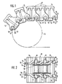
- Ein Ausführungsbeispiel der Erfindung ist in der Zeichnung dargestellt und in der nachfolgenden Beschreibung näher erläutert. Es zeigen:
- Figur 1 einen Teil eines Plattenbandförderers in Seitenansicht und
- Figur 2 einen Teil eines Trummes des Plattenbandförderers nach Figur 1 in Unteransicht.
- Der Plattenbandförderer hat eine endlose Gelenkkette 10 mit seitlich abstehenden Gelenkbolzen 11 und an diesen befestigte Tragelemente 12. Die Kette 10, die in Figur 1 vereinfacht als strichpunktierte Linie dargestellt ist, ist über Kettenräder 13 geführt und angetrieben, von denen eines ebenfalls vereinfacht strichpunktiert dargestellt ist.
- Die Tragelemente 12 haben je eine Platte 14, die sich in der Förderebene waagerecht erstreckt und zwei von der Platte 14 nach unten abstehende, sich in Förderrichtung erstreckende Füsse 15, 16. Der in Förderrichtung vorne liegende Bereich der Füsse 15, 16 ist gegenüber dem hinten liegenden jeweils spiegelbildlich seitlich um die Dicke eines Fusses versetzt, so dass die Fusspaare benachbarter, hintereinander angeordneter Trageiemente 12 teilweise ineinandergreifen können. Zum Befestigen der Tragelemente 12 an der Kette 10 haben die Füsse 15, 16 jeweils eine vordere und eine hintere Klaue 17, 18. Der Abstand der beiden Klauen 17, 18 eines Fusses 15, 16 ist gleich dem Abstand zweier Gelenkbolzen 11 der Gelenklette 10. Die Klauen 17, 18 umgrenzen eine Bohrung 19, 20, deren Durchmesser gleich dem der Gelenkbolzen 11 ist, und ein schlitzartiges Maul 21, 22. Das Maul 21 der in Förderrichtung vorne liegenden Klauen 17 ist quer zur Ebene einer Platte 14 nach unten und das Maul 22 der in Förderrichtung hinten liegenden Klauen 18 in einem Winkel von etwa 45° schräg zur Ebene der Platten 14 nach hinten und unten gerichtet. Die Weite der Mäuler 21,22 der Klauen 17, 18 ist etwas kleiner als der Durchmesser der Gelenkbolzen 11, so dass diese formschlüssig drehbar in den Bohrungen 19, 20 rasten.
- Um den Tragelementen 12 auf den Gelenkbolzen 11 der Kette 10 einen sicheren Halt auch bei Stössen und Widerständen zu verleihen, sind die Füsse 15, 16 im Bereich ihrer Klauen 17, 18 formschlüssig aber auch gelenkig miteinander verbunden. Dazu ist an den vorderen Klauen 17 auf der den hinteren Klauen 18 zugewandten Seite ein Vorsprung 23 in Form eines Ringes angeordnet, der durch das Maul 21 unterbrochen ist. Der ringförmige Vorsprung 23 ist gleichachsig zur Achse der Bohrung 19 der Klauen 17. Komplementär zu den Vorsprüngen 23 der Klauen 17 haben die hinteren Klauen 18 auf ihrer äusseren, den vorderen Klauen 17 zugewandten Seite eine ringförmige Aussparung 24, in die der Vorsprung 23 der jeweils anliegenden Klaue 17 formschlüssig eingreift. Durch diese axiale, gelenkige Verbindung der jeweils vorderen Klaue 18 eines nacheilenden Tragelements 12 mit den jeweils hinteren Klauen 19 eines voreilenden Tragelements 12 wird ein guter Halt der Tragelemente 12 an den Gelenkbolzen 11 der Kette 10 sichergestellt. Die Halterungssicherheit wird noch dadurch erhöht, dass die Öffnungsrichtung der Mäuler 21, 22 der vorderen und der hinteren Klauen um einen Winkel versetzt ist, so dass sich der Formschluss durch den kombinierten Umfassungswinkel zweier zusammenwirkender Klauen 17 und 18 beinahe über den ganzen Umfang der Gelenkbolzen 11, beim Ausführungsbeispiel über 315° erstreckt. Der kombinierte Formschluss über den gesamten Umfang kann erreicht werden, wenn die Öffnungsrichtung der Mäuler 21 und 22 zweier benachbarter Klauen 17, 18 um 90° und mehr versetzt ist.
- Das Bestücken der Gelenkkette 10 mit Tragelementen 12 geht folgendermassen vor sich:
- Jeweils ein Tragelement 12 wird mit seinen in Förderrichtung hinten liegenden Klauen 18 an einem Gelenkbolzen 11 in schräg nach hinten geneigter Stellung angesetzt und durch Druck auf die Tragplatte 14 werden die Klauen 18 auf den Gelenkbolzen 11 geschoben, so dass die Gelenkbolzen in den Bohrungen 20 einrasten. Beim Aufschieben auf den Gelenkbolzen 11 weitet sich das Maul 22 der Klaue 18 etwas aufgrund der Elastizität des Werkstoffes, aus dem das Tragelement 12 hergestellt ist. Danach wird das Tragelement 12 in Förderrichtung nach vorne geschwenkt, so dass die vorderen Klauen 17 am vorauseilenden Gelenkbolzen 11 anliegen. Unter der Einwirkung von Druck auf die Tragplatte 14 schnappen dann auch die vorderen Klauen 17 auf dem vorauseilenden Gelenkbolzen 11 in ähnlicher Weise wie oben beschrieben ein. In gleicher Weise werden nacheinander die jeweils in Förderrichtung nacheilenden Tragelemente 12 an der Kette 10 befestigt. Um das Einführen der Vorsprünge 23 in die Aussparungen 24 der Klauen 17, 18 zu gewährleisten, haben die Vorsprünge 23 an der Stelle, die beim Schwenken der Tragelemente 14 zum Ansetzen an den Gelenkbolzen zuerst an den Füssen 15, 16 im Bereich der hinteren Klauen 18 zur Anlage kommen, etwas angeschrägt, so dass ein Einfädeln unter elastischem Ausweichen der benachbarten Klauen 17,18 und Überschieben möglich ist.
Claims (4)
Applications Claiming Priority (2)
| Application Number | Priority Date | Filing Date | Title |
|---|---|---|---|
| DE19843413910 DE3413910A1 (de) | 1984-04-13 | 1984-04-13 | Plattenbandfoerderer |
| DE3413910 | 1984-04-13 |
Publications (2)
| Publication Number | Publication Date |
|---|---|
| EP0161347A1 EP0161347A1 (de) | 1985-11-21 |
| EP0161347B1 true EP0161347B1 (de) | 1987-09-16 |
Family
ID=6233451
Family Applications (1)
| Application Number | Title | Priority Date | Filing Date |
|---|---|---|---|
| EP84116264A Expired EP0161347B1 (de) | 1984-04-13 | 1984-12-22 | Plattenbandförderer |
Country Status (4)
| Country | Link |
|---|---|
| US (1) | US4643297A (de) |
| EP (1) | EP0161347B1 (de) |
| JP (1) | JPS60228310A (de) |
| DE (2) | DE3413910A1 (de) |
Families Citing this family (13)
| Publication number | Priority date | Publication date | Assignee | Title |
|---|---|---|---|---|
| JPH0624943Y2 (ja) * | 1986-08-27 | 1994-06-29 | 富士電機株式会社 | 自動販売機の水平コンベア式商品搬送棚 |
| DE8816581U1 (de) * | 1988-08-26 | 1989-11-30 | Rau Maschinenbau GmbH, 7014 Kornwestheim | Förderband |
| US5377819A (en) * | 1993-07-02 | 1995-01-03 | The Laitram Corporation | Conveyor apparatus and method |
| US5361893A (en) * | 1993-11-18 | 1994-11-08 | The Laitram Corporation | High friction plastic conveyor belts having modular links formed by two integrated plastic materials |
| DE29704065U1 (de) * | 1997-03-06 | 1997-05-15 | B & F Bauservice GmbH, 24641 Stuvenborn | Antriebskette |
| DE10041269C2 (de) * | 1999-10-13 | 2003-04-30 | Rau Maschb Gmbh | Bandförderer |
| MXPA02007280A (es) * | 2000-01-28 | 2002-12-09 | Stevens Design Fabrication Inc | Cadena acojinada para un transportador. |
| US6308823B1 (en) | 2000-01-28 | 2001-10-30 | Stevens Design & Fabrication, Inc. | Padded chain for a conveyor |
| DE10126999B4 (de) * | 2001-06-05 | 2005-02-10 | Rau Maschinenbau Gmbh | Bandförderer |
| DE10146981A1 (de) * | 2001-09-24 | 2003-04-10 | Siemens Ag | Stauförderer zum Transport von Stückgut, insbesondere Werkstückträgern |
| US20060205550A1 (en) * | 2004-05-27 | 2006-09-14 | Byron Anderson | Link chain and associated methods |
| US8905228B2 (en) * | 2013-02-04 | 2014-12-09 | Laitram, L.L.C. | Self-supporting conveyor belt |
| EP3237174B1 (de) | 2014-12-22 | 2019-03-20 | 3M Innovative Properties Company | Vorrichtung und verfahren zum strecken und fortbringen von polymerfolien |
Family Cites Families (8)
| Publication number | Priority date | Publication date | Assignee | Title |
|---|---|---|---|---|
| US1800663A (en) * | 1926-10-14 | 1931-04-14 | Chain Belt Co | Conveyer flight |
| US3231069A (en) * | 1961-10-24 | 1966-01-25 | William E Lanham | Chain link |
| DE1281350B (de) * | 1967-09-06 | 1968-10-24 | Ruberg & Renner G M B H | Transportkette |
| DE1944026C2 (de) * | 1969-08-29 | 1984-10-25 | Shelcon, Inc., Alhambra, Calif. | Plattenförmiges Förderglied |
| BE788691A (fr) * | 1972-09-15 | 1973-01-02 | Umec Boydell Belting Ltd | Perfectionnements apportes aux transporteurs a bande sans fin |
| US4050323A (en) * | 1976-01-12 | 1977-09-27 | Anson Thomas I | Pintle-type industrial conveyor chain |
| NL7712761A (nl) * | 1977-11-18 | 1979-05-22 | Stork Apparatenbouw Bv | Combinatie schalmketting met dragers, alsmede dragerbak uit een dergelijke combinatie. |
| US4469221A (en) * | 1982-09-24 | 1984-09-04 | Scapa Inc. | Papermakers fabric of link and pintle construction |
-
1984
- 1984-04-13 DE DE19843413910 patent/DE3413910A1/de not_active Withdrawn
- 1984-12-22 EP EP84116264A patent/EP0161347B1/de not_active Expired
- 1984-12-22 DE DE8484116264T patent/DE3466201D1/de not_active Expired
-
1985
- 1985-01-25 US US06/695,110 patent/US4643297A/en not_active Expired - Fee Related
- 1985-04-10 JP JP60074568A patent/JPS60228310A/ja active Pending
Also Published As
| Publication number | Publication date |
|---|---|
| US4643297A (en) | 1987-02-17 |
| DE3413910A1 (de) | 1985-10-24 |
| DE3466201D1 (en) | 1987-10-22 |
| JPS60228310A (ja) | 1985-11-13 |
| EP0161347A1 (de) | 1985-11-21 |
Similar Documents
| Publication | Publication Date | Title |
|---|---|---|
| EP0161347B1 (de) | Plattenbandförderer | |
| DE19512088C2 (de) | Energiekette | |
| DE69203931T2 (de) | Förderer zum Transportieren von Behältern. | |
| DE68910609T2 (de) | Transportförderer für Gegenstände. | |
| EP2212224B1 (de) | Vorrichtung zum abstreifen von verunreinigungen eines gurtbandes von förderbandanlagen | |
| EP1561064A1 (de) | Verbindungselement | |
| DE3022065C2 (de) | Transportkette | |
| DE3310917C2 (de) | ||
| DE2922024C2 (de) | Filterelement für Spaltfilter | |
| EP0760438A1 (de) | Förderband zur Verwendung in einer Fördervorrichtung mit einer Muldungszone | |
| EP1558507B1 (de) | Mitnehmer für kettenkratzförderer, insbesondere des untertagebetriebes | |
| DE4025706C2 (de) | Plattenförderband | |
| DE2061395B2 (de) | Verschlußglied für Reifengleitschutzketten | |
| WO2005036025A1 (de) | Kettenlasche, kettenglied und energieführungskette, sowie zwischenstück für eine energieführungskette, mit torsionsgekoppelten verriegelungsmitteln zum verbinden von quersteg und kettenlasche | |
| DE2460176C2 (de) | Rinnenschußverbindung für einen Kettenkratzförderer mit einer hieran angeordneten Hobelkettenführung | |
| DE202004002161U1 (de) | Verkürzungsklaue | |
| CH671946A5 (de) | ||
| DE4329909C2 (de) | Klemmvorrichtung für Bauelemente | |
| DE3616801C1 (de) | Gurtbecherwerk fuer Senkrechtfoerderer | |
| DE3402529A1 (de) | Kurvengaengiger plattenbandfoerderer | |
| DE2159826C2 (de) | Reifenkette | |
| AT405894B (de) | Element zum schliessen einer öffnung, insbesondere eine klemmeinrichtung | |
| DE941596C (de) | Mitnehmerband fuer Stauscheibenfoerderer | |
| DD228232A1 (de) | Vorrichtung zum ordnen bolzenfoermiger werkstuecke | |
| EP0825135A1 (de) | Förderelement mit daran befestigtem Transportkörper |
Legal Events
| Date | Code | Title | Description |
|---|---|---|---|
| PUAI | Public reference made under article 153(3) epc to a published international application that has entered the european phase |
Free format text: ORIGINAL CODE: 0009012 |
|
| 17P | Request for examination filed |
Effective date: 19841222 |
|
| AK | Designated contracting states |
Designated state(s): DE FR GB IT |
|
| 17Q | First examination report despatched |
Effective date: 19860813 |
|
| GRAA | (expected) grant |
Free format text: ORIGINAL CODE: 0009210 |
|
| AK | Designated contracting states |
Kind code of ref document: B1 Designated state(s): DE FR GB IT |
|
| ET | Fr: translation filed | ||
| REF | Corresponds to: |
Ref document number: 3466201 Country of ref document: DE Date of ref document: 19871022 |
|
| GBT | Gb: translation of ep patent filed (gb section 77(6)(a)/1977) | ||
| ITF | It: translation for a ep patent filed | ||
| PLBE | No opposition filed within time limit |
Free format text: ORIGINAL CODE: 0009261 |
|
| STAA | Information on the status of an ep patent application or granted ep patent |
Free format text: STATUS: NO OPPOSITION FILED WITHIN TIME LIMIT |
|
| 26N | No opposition filed | ||
| ITTA | It: last paid annual fee | ||
| PGFP | Annual fee paid to national office [announced via postgrant information from national office to epo] |
Ref country code: GB Payment date: 19921214 Year of fee payment: 9 |
|
| PGFP | Annual fee paid to national office [announced via postgrant information from national office to epo] |
Ref country code: FR Payment date: 19921229 Year of fee payment: 9 |
|
| PG25 | Lapsed in a contracting state [announced via postgrant information from national office to epo] |
Ref country code: GB Effective date: 19931222 |
|
| GBPC | Gb: european patent ceased through non-payment of renewal fee |
Effective date: 19931222 |
|
| PG25 | Lapsed in a contracting state [announced via postgrant information from national office to epo] |
Ref country code: FR Effective date: 19940831 |
|
| REG | Reference to a national code |
Ref country code: FR Ref legal event code: ST |
|
| PGFP | Annual fee paid to national office [announced via postgrant information from national office to epo] |
Ref country code: DE Payment date: 20040210 Year of fee payment: 20 |