EP0161364A1 - Pochette utilisée pour garder des films en monture - Google Patents
Pochette utilisée pour garder des films en monture Download PDFInfo
- Publication number
- EP0161364A1 EP0161364A1 EP84307952A EP84307952A EP0161364A1 EP 0161364 A1 EP0161364 A1 EP 0161364A1 EP 84307952 A EP84307952 A EP 84307952A EP 84307952 A EP84307952 A EP 84307952A EP 0161364 A1 EP0161364 A1 EP 0161364A1
- Authority
- EP
- European Patent Office
- Prior art keywords
- film
- housing
- surface plate
- back surface
- Prior art date
- Legal status (The legal status is an assumption and is not a legal conclusion. Google has not performed a legal analysis and makes no representation as to the accuracy of the status listed.)
- Withdrawn
Links
- 238000007789 sealing Methods 0.000 claims description 6
- 239000011159 matrix material Substances 0.000 abstract description 2
- 230000002093 peripheral effect Effects 0.000 description 5
- 229920003002 synthetic resin Polymers 0.000 description 3
- 239000000057 synthetic resin Substances 0.000 description 3
- 230000003247 decreasing effect Effects 0.000 description 2
- 230000004927 fusion Effects 0.000 description 2
- 238000003780 insertion Methods 0.000 description 2
- 230000037431 insertion Effects 0.000 description 2
- 230000004048 modification Effects 0.000 description 2
- 238000012986 modification Methods 0.000 description 2
- 229920005989 resin Polymers 0.000 description 1
- 239000011347 resin Substances 0.000 description 1
Images


Classifications
-
- G—PHYSICS
- G03—PHOTOGRAPHY; CINEMATOGRAPHY; ANALOGOUS TECHNIQUES USING WAVES OTHER THAN OPTICAL WAVES; ELECTROGRAPHY; HOLOGRAPHY
- G03B—APPARATUS OR ARRANGEMENTS FOR TAKING PHOTOGRAPHS OR FOR PROJECTING OR VIEWING THEM; APPARATUS OR ARRANGEMENTS EMPLOYING ANALOGOUS TECHNIQUES USING WAVES OTHER THAN OPTICAL WAVES; ACCESSORIES THEREFOR
- G03B21/00—Projectors or projection-type viewers; Accessories therefor
- G03B21/54—Accessories
- G03B21/64—Means for mounting individual pictures to be projected, e.g. frame for transparency
Definitions
- the present invention relates to a film-housing pocket which is suitably used for arranging and storing a film mounted on a mount, and a film-housing pocket assembly.
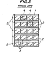
- the laterally and vertically arranged pockets 3 exhibit functions of effectively arranging and storing the slide films 4 when the mounted slide film 4 is completely inserted into the interior of the pocket 3 through its mouth as shown in Fig. 5.
- a reference numeral 5 shows a binding hole of the mounted film-housing assembly in which a plurality of housing pockets 3 are laterally and vertically arranged.
- the width of the pocket 3 is made slightly wider than that of the slide film 4 with the mount.
- the housing pocket 3 is constituted by joining the back surface plate 1 and the front surface plate 2 in a form of a U-shaped completely continuous three direction sealing, when the slide film 4 attached to a relatively thick mount made of plastic, paper or the like is assuredly pushed into the housing pocket 31 down to a specified location, the frictional force between the peripheral portion of the mount and the peripheral portion of the pocket becomes considerably larger, so that a fairly large pushing insertion force is necessary. This is more serious in the case where the front and back surface plates become hard as in winter.
- the pocket has the drawback that deflection is produced at either one of the front or back surface plates and in the worst case, the whole pocket 3 and in turn the whole film-housing pocket assembly are deflected in either direction, when the mounted slide film 4 is pushed into the pocket 3.
- the object of the present invention is to provide a mounted film-housing pocket which facilitates the insertion of a mounted film into the pocket at a predetermined position through decreasing the frictional force between the peripheral portion of a mount and the peripheral portion of the pocket when the mounted film is pushed into the pocket.
- a non-joining portion where the front and back surface plates are not joined together is provided at at least one of the side portions and bottom portion of the pocket constituted by sealing the back surface plate and the front surface plate together at the side portions and bottom portion, whereby the frictional force between the mount of the mounted film and the peripheral portions of the pocket is effectively reduced to extremely facilitate the fully pushing of the film into the pocket.
- a mounted film-housing pocket assembly comprising a substantially rectangular back surface plate made of transparent or translucent sheet, and a plurality of transversely long front surface plates made of transparent sheet, said front surface plates being arranged on the back surface plate while being vertically spaced from the adjacent ones, and sealed to the back surface plate at the bottom edge and vertically spaced lines so as to define film-housing pockets each defined by the bottom edge and the adjacent vertical lines and between the front surface plate and the back surface plate in such a manner that a non-joining portion where the front and back surface plates are not joined together is formed in the sealing portions of each of the film-housing pockets at at least one of the side portions and the bottom portion thereof.
- Fig. 1 shows embodiments according to the present invention.
- a front surface plate 2 made of a transparent resin sheet is sealed to a back surface plate 1 made of a transparent or translucent synthetic resin sheet through thermal fusion or adhesion as shown by shadow portions in Fig. la to form a mounted film-housing pocket 3 of a substantially rectangular shape, provided that a non-joining portion 11 where the front surface plate 1 and the back surface plate 2 are not joined together is provided at the central portion of the bottom portion of the housing pocket 3, while in the embodiment of Fig. lb, a cut portion 12 also serving as a finger hole for taking out the slide film 4 is provided in the front surface plate 2 at the non-joining portion 11.
- a plurality of the film-housing pockets are laterally and vertically formed between the back surface plate and the transversely long front surface plate in a matrix manner so as to constitute a film-housing pocket assembly.
- the non-joined portion 11 when the mounted slide film 5 is inserted into the pocket 3 down to the predetermined position, the non-joined portion 11 functions to effectively reduce the resistance in pushing the slide film 4 particularly in the vicinity of the bottom portion of the pocket 3, so that the pushing of the film into the predetermined location of the pocket is extremely facilitated.
- Fig. 2 shows plan views of further embodiments according to the present invention, Fig. 2a being the embodiment in which non-joining portions 13 where the front and back surface plates 2 and 1 are not joined is formed at the central portions of both side portions of the pocket 3 in the depth direction thereof.
- a cut line 14 extending in the depth direction of the pocket 3 is provided on each side portion of the pocket 3 and at least one of the front surface plate 2 and the back surface plate 1.
- the cut lines 14 serve to separate at least the one of the front and back surface plates 2 and 1 from the sealing portions on the both side portions of the pocket, they act as they were non-joining portions between the front and back surface plates 2 and 1, and facilitate the deformation of the front and back surface plates positioned between the cut lines 14, 14, in the spacing direction. Therefore, the non-joining portion referred to in this specification includes such a cut line.
- the non-joining portion 13 or cut line 14 facilitates the deformation of, for instance, the front surface plate 2 to reduce the resistance in pushing the slide film 4 into the pocket 3 at the both side portions, it is made easier to completely push the slide film into the pocket 3.
- non-joining portions between the front and back surface plates 2 and 1 are provided onto the both side portions and the bottom portion of the pocket 3, so that the resistance in pushing the slide film 4 into the pocket is reduced.
- the housing pocket is so constituted that the non-joining portions 15 and 16 are formed at the central portion and the lower end of each of the both side portions of the pocket 3, while the non-joining portions 17 and 18 are provided at the central portion and the both side portions of the bottom portions of the pocket. Further a cut portion 19 is formed in the front surface plate 2 at the non-joining portion 17.
- the housing pocket 3 is so constituted that a non-joining portion 20 between the front and back surface plates 2 and 1 is formed at a portion extending from the lower end portion of the side portion of the pocket to the adjacent side portion of the bottom portion of the pocket 3, and a non-joining portion 21 is formed at the central portion of the bottom portion. Further, a substantially triangular cut portion 22 and a substantially rectangular portion 23 are formed in the front surface plate 2 at the non-joining portion 20 and 21 respectively.
- the location, number, profile and so forth of the non-joining portions may be appropriately varied depending upon the necessity so long as the intrinsic function of the housing pocket is not deteriorated.
Landscapes
- Physics & Mathematics (AREA)
- General Physics & Mathematics (AREA)
- Sheet Holders (AREA)
- Silver Salt Photography Or Processing Solution Therefor (AREA)
Applications Claiming Priority (2)
| Application Number | Priority Date | Filing Date | Title |
|---|---|---|---|
| JP59053988A JPS60198296A (ja) | 1984-03-21 | 1984-03-21 | マウント付きフイルムの収納ポケツト |
| JP53988/84 | 1984-03-21 |
Publications (1)
| Publication Number | Publication Date |
|---|---|
| EP0161364A1 true EP0161364A1 (fr) | 1985-11-21 |
Family
ID=12957999
Family Applications (1)
| Application Number | Title | Priority Date | Filing Date |
|---|---|---|---|
| EP84307952A Withdrawn EP0161364A1 (fr) | 1984-03-21 | 1984-11-16 | Pochette utilisée pour garder des films en monture |
Country Status (2)
| Country | Link |
|---|---|
| EP (1) | EP0161364A1 (fr) |
| JP (1) | JPS60198296A (fr) |
Cited By (2)
| Publication number | Priority date | Publication date | Assignee | Title |
|---|---|---|---|---|
| EP0285531A1 (fr) * | 1987-03-30 | 1988-10-05 | Inter-Color | Dispositif de conditionnement de diapositives |
| GB2204151A (en) * | 1987-04-10 | 1988-11-02 | P C A Slide Holders Limited | Slide holder |
Families Citing this family (1)
| Publication number | Priority date | Publication date | Assignee | Title |
|---|---|---|---|---|
| JPH08187984A (ja) * | 1995-01-11 | 1996-07-23 | Suraidetsukusu Kk | マウント付フィルムスライドのファイルシート |
Citations (5)
| Publication number | Priority date | Publication date | Assignee | Title |
|---|---|---|---|---|
| US2968882A (en) * | 1957-07-11 | 1961-01-24 | Ozeki Jiro | Translucent plates for use in filing color film slides |
| GB1161130A (en) * | 1966-10-13 | 1969-08-13 | William Crookes | Photographic Slide Storage System and Multiviewer. |
| US3696538A (en) * | 1970-06-22 | 1972-10-10 | Robert Nast | Transparency holder |
| DE2201381A1 (de) * | 1972-01-13 | 1973-07-19 | Hermann & Kraemer Ohg | Flachbehaelter fuer diapositive |
| GB2016738A (en) * | 1978-03-01 | 1979-09-26 | Slidex Corp | Slide file sheet for use during projection |
Family Cites Families (3)
| Publication number | Priority date | Publication date | Assignee | Title |
|---|---|---|---|---|
| JPS5418646U (fr) * | 1977-07-08 | 1979-02-06 | ||
| JPS5435350U (fr) * | 1977-08-12 | 1979-03-08 | ||
| JPS5492346U (fr) * | 1977-12-13 | 1979-06-29 |
-
1984
- 1984-03-21 JP JP59053988A patent/JPS60198296A/ja active Pending
- 1984-11-16 EP EP84307952A patent/EP0161364A1/fr not_active Withdrawn
Patent Citations (5)
| Publication number | Priority date | Publication date | Assignee | Title |
|---|---|---|---|---|
| US2968882A (en) * | 1957-07-11 | 1961-01-24 | Ozeki Jiro | Translucent plates for use in filing color film slides |
| GB1161130A (en) * | 1966-10-13 | 1969-08-13 | William Crookes | Photographic Slide Storage System and Multiviewer. |
| US3696538A (en) * | 1970-06-22 | 1972-10-10 | Robert Nast | Transparency holder |
| DE2201381A1 (de) * | 1972-01-13 | 1973-07-19 | Hermann & Kraemer Ohg | Flachbehaelter fuer diapositive |
| GB2016738A (en) * | 1978-03-01 | 1979-09-26 | Slidex Corp | Slide file sheet for use during projection |
Cited By (3)
| Publication number | Priority date | Publication date | Assignee | Title |
|---|---|---|---|---|
| EP0285531A1 (fr) * | 1987-03-30 | 1988-10-05 | Inter-Color | Dispositif de conditionnement de diapositives |
| FR2613329A1 (fr) * | 1987-03-30 | 1988-10-07 | Inter Color | Dispositif de conditionnement de diapositives |
| GB2204151A (en) * | 1987-04-10 | 1988-11-02 | P C A Slide Holders Limited | Slide holder |
Also Published As
| Publication number | Publication date |
|---|---|
| JPS60198296A (ja) | 1985-10-07 |
Similar Documents
| Publication | Publication Date | Title |
|---|---|---|
| EP0224973B1 (fr) | Feuille de garde pour porteurs d'informations | |
| ATE225441T1 (de) | Modulares blockwand-haltesystem | |
| IL111367A0 (en) | An exchangeable cutting insert | |
| JPS5924544Y2 (ja) | スライドフイルムの整理保存板 | |
| KR850005284A (ko) | 라멜라(lamella)분리기용 평판팩 | |
| EP0610019B1 (fr) | Dispositif de rangement d'une feuille de classement | |
| EP0161364A1 (fr) | Pochette utilisée pour garder des films en monture | |
| GB9707847D0 (en) | File folder having a pocket | |
| US3656651A (en) | Drawer divider | |
| US5358114A (en) | Card holder | |
| US4154338A (en) | Package for information carriers | |
| US4085534A (en) | Data carrier holder | |
| ATE39197T1 (de) | Ablagemittel fuer disketten. | |
| KR940022181A (ko) | 필름을 리더에 연결하기 위한 장치 | |
| JPH0136629Y2 (fr) | ||
| EP0148646B1 (fr) | Etui pour classeur de documents | |
| JPH0136628Y2 (fr) | ||
| US4607443A (en) | Visible index pocket constructions | |
| WO1999052092A1 (fr) | Dispositif de support pour supports d'informations en forme de bande | |
| USD289771S (en) | Electrophotographic copying machine | |
| KR860001582A (ko) | 중첩된 종이 시이트용 발출상자 | |
| KR930021512A (ko) | 플로피 디스크 컨테이너 | |
| EP0354768B1 (fr) | Dispositif de reliure | |
| JPH088146Y2 (ja) | 卓上用電話帳 | |
| AU634316B2 (en) | File sheet for filing information-recording media |
Legal Events
| Date | Code | Title | Description |
|---|---|---|---|
| PUAI | Public reference made under article 153(3) epc to a published international application that has entered the european phase |
Free format text: ORIGINAL CODE: 0009012 |
|
| AK | Designated contracting states |
Designated state(s): DE GB |
|
| STAA | Information on the status of an ep patent application or granted ep patent |
Free format text: STATUS: THE APPLICATION IS DEEMED TO BE WITHDRAWN |
|
| 18D | Application deemed to be withdrawn |
Effective date: 19860721 |
|
| RIN1 | Information on inventor provided before grant (corrected) |
Inventor name: OZEKI, JIRO |