EP0161421A2 - Pompe à huile à engrenages du type à roue mobile interne pour moteurs à combustion interne dans des véhicules automobiles - Google Patents
Pompe à huile à engrenages du type à roue mobile interne pour moteurs à combustion interne dans des véhicules automobiles Download PDFInfo
- Publication number
- EP0161421A2 EP0161421A2 EP85103161A EP85103161A EP0161421A2 EP 0161421 A2 EP0161421 A2 EP 0161421A2 EP 85103161 A EP85103161 A EP 85103161A EP 85103161 A EP85103161 A EP 85103161A EP 0161421 A2 EP0161421 A2 EP 0161421A2
- Authority
- EP
- European Patent Office
- Prior art keywords
- pump
- suction
- kidney
- suction kidney
- working chamber
- Prior art date
- Legal status (The legal status is an assumption and is not a legal conclusion. Google has not performed a legal analysis and makes no representation as to the accuracy of the status listed.)
- Granted
Links
Images


Classifications
-
- F—MECHANICAL ENGINEERING; LIGHTING; HEATING; WEAPONS; BLASTING
- F04—POSITIVE - DISPLACEMENT MACHINES FOR LIQUIDS; PUMPS FOR LIQUIDS OR ELASTIC FLUIDS
- F04C—ROTARY-PISTON, OR OSCILLATING-PISTON, POSITIVE-DISPLACEMENT MACHINES FOR LIQUIDS; ROTARY-PISTON, OR OSCILLATING-PISTON, POSITIVE-DISPLACEMENT PUMPS
- F04C15/00—Component parts, details or accessories of machines, pumps or pumping installations, not provided for in groups F04C2/00 - F04C14/00
-
- F—MECHANICAL ENGINEERING; LIGHTING; HEATING; WEAPONS; BLASTING
- F01—MACHINES OR ENGINES IN GENERAL; ENGINE PLANTS IN GENERAL; STEAM ENGINES
- F01M—LUBRICATING OF MACHINES OR ENGINES IN GENERAL; LUBRICATING INTERNAL COMBUSTION ENGINES; CRANKCASE VENTILATING
- F01M1/00—Pressure lubrication
- F01M1/02—Pressure lubrication using lubricating pumps
Definitions
- Such pumps have recently become increasingly popular for supplying oil to motor vehicle internal combustion engines, in particular piston engines of this type. They have the significant advantage that a separate drive for the oil pump is not necessary, since the extension of the crankshaft, which, as is preferred and usually the case, is formed by the free end of the crankshaft, but can also be a separate part , can directly drive the pinion.
- the pinion can sit directly on the crankshaft. However, it is preferably seated on a separate bearing collar formed in the housing of the pump and is driven by the crankshaft passing through this collar via drivers.
- the flow direction in the feed channel is approximately tangential to the central circumferential direction of the pump gearwheels in the suction kidney region.
- the projection of the direction of flow in the feed channel in the area in which it merges into the suction kidney area should have a direction on a normal plane of the axis of rotation of the pump which approximately coincides with the direction of movement of the teeth of the pinion and the ring gear in this area.
- the channel can also open into the suction kidney, for example, parallel to the pump axis. This can be the case in particular when the pump is used in an automatic motor vehicle transmission.
- the feed channel which has the same circular cross section at the end of the oil suction pipe as the oil suction pipe, extends with a tapering circular cross section to the suction kidney.
- the oil supply channel runs partly on the working chamber side of the end wall of the working chamber containing the suction cups and partly on the side of this end wall applied to the working chamber.
- the course of the feed channel is such that the oil flow not only flows around the suction face end face of the ring gear, but also a part of the peripheral surface of the ring gear.
- the pump according to the older application P 32 43 067.1 eliminates this disadvantage.
- the delivery capacity of the pump can be increased further, at least to a large extent approximately proportional to the speed, without increasing its dimensions, even in a higher speed range, if this output otherwise drops sharply; one avoids that which often occurs with other pumps Foaming even at higher speeds.
- the oil flow occurs approximately tangentially to the direction of rotation of the toothing in a suction kidney arranged on the side of the end wall of the working chamber facing away from the working chamber, which extends in the direction of rotation and reduces its cross section in the direction of rotation and which ends considerably in front of the plane containing the gearwheel axes.
- the invention solves the problem, both in the known pump and - and in particular - in the pump according to the earlier application P 32 43 067.1 to improve the performance, that is to say the delivery rate in the unit of time, by means of favorable formation of the oil inflow.
- the pump which is sealed in a known manner by a sickle-shaped filler arranged in the working chamber, is provided with a suction kidney which, as before, does not end well before the symmetry level of the pump, but, in contrast, extends almost to or preferably beyond the plane of symmetry (the plane containing the two gearwheel axes) of the pump. Surprisingly, this results in a significant improvement in the output.
- the suction kidney extends beyond the plane of symmetry by 20 to 30 °, based on the axis of rotation of the pinion, preferably 25 °. Because the filler with its cylindrical surfaces The delivery spaces formed by the interdental spaces of the ring gear or pinion, which constantly move from the suction side to the delivery side, are open to the suction kidney by the invention over a considerable length of their movement path, so that a longer period of time for filling said delivery spaces Is available than was previously the case. Therefore, even at a high speed, the time during which the said delivery spaces are filled with liquid is sufficient to ensure that these delivery spaces always fill well. The invention has the effect that, up to an unusually high speed, the already high delivery rate of the pump is approximately proportional to the speed.
- the suction kidney not only extends radially outside the filler beyond the plane of symmetry, but is at its end pointing in the direction of rotation divided into two branches that run on both sides of the filler.
- the delivery rate is particularly high when the start of the pressure kidney is at a distance of only about two gear wheel divisions from the two ends of the suction kidney branches in the circumferential direction. This means that the distance between the ends of the inner and outer suction kidney branch and the pressure kidney beginning approximately in the region of the end of the filling piece in Circumferential direction measured at half the tooth height of the pinion or the ring gear. If the ends of the suction kidney branches now lie, for example, on a radial jet of the pinion or ring gear, then the beginnings of the pressure kidneys do not lie on a radial jet.
- the cross section of the feed channel should only be slightly reduced to avoid losses up to the transition into the suction kidney. However, a small reduction is considered to be expedient in order to ensure a good transition of the channel cross section into the suction kidney.
- the particularly long suction kidney according to the invention could be kept relatively flat and then still ensure a particularly good filling level of the pump. According to the embodiment of claim 5, however, their depth decreases continuously to the end, so that only relatively small changes in speed and direction of the oil flow occur in the region of the suction kidney.
- a recess is provided on the front side of the pump opposite the suction grille, then this brings about a very substantial further increase in the delivery rate. Surprisingly, a considerable improvement already occurs when the recess is only connected to the suction kidney via the mentioned delivery spaces.
- the suction grille and the recess can also be connected to one another by a channel provided in the housing, which, however, should not touch the peripheral wall of the gear chamber in order not to weaken the bearing of the ring gear.
- the configuration according to claim 7 is preferred.
- the end of the filler piece opposite the direction of rotation of the pump is chamfered in such a way that the current is deflected more towards the branch of the suction kidney running radially inside the filler piece in order to compensate for the effect of the centrifugal force.
- This configuration simultaneously leads to a shortening of the filling piece, which in turn leads to the fact that in the region of this shortening a cavity is formed which is connected to the suction kidney and extends transversely to the tooth flanks of the gears and which in turn further improves the filling of the delivery spaces.
- the filler is not carried out at the other end s p itzauslau- fend, but shortened for reasons of strength minor.
- a preferred embodiment of the invention is that the cover of the pump has a recess which preferably corresponds to the shape of the suction kidney.
- This recess extends like the pressure kidney in two branches on both sides of the filler.
- the cover is thus weakened precisely in the area in which it would have to bring about the reliable sealing between the pressure and suction side by means of a particularly saturated system.
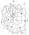
- the pump shown has a housing 1 which - except for the special design of the working chamber and the pressure and suction kidneys - does not differ from that housing which is already described in the earlier application P 32 43 067.1.
- the pump has, as can be seen from the drawings, a housing 1, a working chamber cover 2 shown in detail in FIG. 5, a ring gear 4 (FIGS. 2 to 4) with its circumferential surface mounted on the circumferential wall of the working chamber 3 with, for example, sixteen teeth and a with its bore on a bearing collar 5 integrally formed with the housing 1 rotatably mounted pinion 6 (Fig. 2 to 4) which meshes with the ring gear 4 and, for example has thirteen teeth.
- the pump also has a safety valve, not shown in the drawings, the receptacle of which is shown at 7 and whose function will be discussed further below.
- the housing 1 is flanged to the motor with its side facing the viewer in FIG. 1.
- the oil is supplied from below through an intake duct, not shown, which is connected to a supply duct 9 in the interior of the housing 1.
- the pump housing 1 also has a further flange surface 10 with which it is flanged to the oil pan.
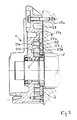
- the working chamber cover 2 is seated on the surface 16 (FIG. 1) of the cast pump housing 1 which is set back from the flange surface 1 by a little more than the thickness of the working chamber cover 2 and thus forms the second end wall of the working chamber 3.
- the two gear wheels 4 and 6 rotate in the cylindrical working chamber.
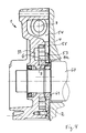
- the drive takes place by means of the end of the crankshaft 60 of the internal combustion engine, which projects through the bore of the bearing collar 5 and carries the pinion 6, which drives the ring gear 4, by means of a drive ring 61.
- the driver ring 61 has projections which engage in corresponding recesses in a collar 6a of the pinion.
- the axis of rotation of the pinion 6 is offset eccentrically with respect to the axis of rotation of the ring gear 4.
- 0 denotes the axis of the pinion 6 (not shown in FIG. 1)
- Q ′ denotes the axis of the ring gear 4.
- the two axes O, O ' run parallel to one another and define a plane of symmetry, the trace of which forms the straight line 51 in FIG.
- This straight line 51 in FIG. 1 contains the point of the deepest tooth engagement on the underside of the housing and the point of the greatest distance between the teeth on the top.
- the pump shown in the drawing is a filler pump, in which the two gear wheels 4, 6 are far apart at the point of their greatest distance and enclose a crescent or crescent-shaped cavity between them, which is formed by an appropriately designed, over the entire depth of the working chamber 3rd extending solid filler 50 filled
- the plane of symmetry 51 is at an angle of 10 ° in the sense of the clockwise rotation in FIG. 1 and opposite to the normal plane pointing vertically downward on the flange surface 10 in FIG. 1 through the axis of rotation O of the pinion 6 the direction of rotation of the pump indicated by arrow 25; this allows an advantageous guidance of the feed channel 9, which starts from the flange surface 10.
- Fig. 1 can also be seen an outlet kidney 26 which is recessed in the end wall of the working chamber 3 belonging to the housing 1 and also has an extension 27 in the peripheral wall of the working chamber. From the extension 27, an outlet channel 28 extends to an annular groove 29 which runs around part of the pump and connects to a further pressure oil channel of the pump housing at its right end in FIG. 6.
- the groove 29 becomes a closed channel by flanging onto a suitable surface of the internal combustion engine.
- the feed channel 9 has the cross section of an elongated hole which extends parallel to the plane of the drawing in FIG. 1, is offset somewhat below the working chamber 3 below the working chamber and opens tangentially into the suction grille 33. It is stepless and continuous according to the principles of FIG Fluid mechanics in the suction kidney 33 over.
- the suction kidney 33 covers approximately 180 ° of the working chamber 3 and thus not only reaches up to the plane of symmetry 51, son it still extends by about 25 ° beyond this, that is to say also beyond the normal plane shown in FIG. 1.
- the suction kidney 33 encompasses the filler 50 over more than half of its extent with a radially outer branch 33a and a radially inner branch 33b.
- the filler 50 has a bevel 52 at its end opposite to the direction of rotation 25, which widens the inlet into the inner branch 33b of the suction grille 33 and ensures that the liquid flowing in approximately tangentially from the feed channel 9 is already in the area of the filler 50 is deflected and thus also exposed to the influence of centrifugal force, is skimmed off in such a way that the two branches 33a and 33b are supplied with liquid more uniformly.
- the two branches 33a, b of the suction kidney 33 have a depth that decreases in the direction of rotation 25 to zero, as shown in FIG. 7 (section VII-VII in FIG. 1).
- the ring channel 29 opens into a pressure relief valve (not shown) which overflows into an overflow chamber 54 which is arranged radially outside the working chamber 3 in the vicinity of the bevel 52.
- the valve relieves the annular channel 29 to the overflow chamber 54.
- This is connected to the suction kidney 33 through the channel 65 and is also connected by an overflow 55, which can best be seen in FIGS. 4 and 6, to the recess 53 of the cover 2, which corresponds in shape to the suction kidney and this opposite.
- This working chamber cover 2 can be seen from FIG. 2 and has no special features apart from recesses for fastening screwdrivers.
- Fig. 5 shows the inner surface.
- the cover 2 has a series of cutouts, namely a first cutout 53, which corresponds approximately in shape and depth to the suction grille 33, and a second cutout 56.
- the cutout 53 ends in two branches which, when the cover is mounted, lie over the two branches 33a, b and are separated from one another by a material web which has remained standing and which is seated on the filler 50 and has exactly its contour.
- the second recess 56 is arranged above the pressure kidney 26 and covers it and its extension 27.
- the two cutouts 53 and 56 each form a space adjacent to the working chamber or the gear wheels 4, 6.
- the space formed by the recess 56 is connected via the extension 27, which extends radially outside the working chamber over its height, with the pressure kidney 26 and ensures that the supplied pressure oil can escape on both sides of the gears 4, 6 and then collected through the outlet channel 28 flows.
- the cover 2 is cut out in the peripheral region of the recess 53 corresponding to the suction kidney 33. This cutout is delimited by a cutting edge which, starting from the circumference of the cover 2, runs approximately tangentially against the outer flank of the web supported on the filler 50, at a location which is approximately one third behind that end of the web, that lies above the bevel 52. From there, the recess branch 53a corresponding to the outer suction kidney branch 33a is delimited transversely to its extent by a cutting edge, and a third cutting edge then extends from here in a direction approximately perpendicular to the plane of symmetry 51 to the edge of the cover 2.
- This section 55 can be seen in FIGS. 2 and 4 creates the overflow between the recess 53 and the overflow chamber 54, into which the pump's DrudkbezeMgungsventil, which lies between the channel 29 and the chamber 54, feeds.
- the overflow could also be in the form of a recess in the peripheral wall of the working chamber, which connects the suction kidney 33 to the opening 53.
- this is less advantageous because the bearing of the locking wheel suffers.
- the depth of the recess branches 53a, 53b in the direction of rotation is reduced to zero.
- This gasket is a flat gasket insert, comparable to a cylinder head gasket of an engine, and like this it has the main purpose of sealing liquid-filled spaces from the outside. Accordingly, a section 57a is provided which surrounds the outlet channel 28 and seals off to the outside, and a section 57b which surrounds the overflow chamber 54 and seals off to the outside.
- a third section 57c is provided which, together with a part of section 57b, runs in an arcuate manner and precisely sits above the web of the cover 2 and thus above the filler 50, as can be clearly seen from FIG. 3.
- this sealing section 57c performs a supporting function, namely that the cover 2 has the very small wall thickness shown in FIG. 6 in the region of the inlet into the recess branch 53b, while the overflow still occurs in the region of the inlet into the recess branch 53a 55 extends. Only after the end of the two inlet branches 53a, 53b, viewed in the direction of rotation, does the cover regain its full strength and thus also bending strength.
- the cover performs an essential sealing function between the suction and pressure sides of the pump. It is precisely in this area that weak points in the cover could ensure that it gives way and thus creates a loss of flow against the conveying direction. However, this is prevented by the sealing section 57c, which on the one hand rests firmly on the cover and on the other hand on the contact surface of the motor shown in FIGS. 3 and 4 and thus prevents that critical area of the cover 2 from yielding.
- a pressure equalization is always established between the suction cardioid 33 and the opposite cover recess 53, since in this area the teeth of the two gear wheels 4, 6 diverge and spaces are thus formed between these teeth are. Only in the area of the branches 33a, b or 51a, b could different pressure conditions arise due to the decreasing depth and the special flow conditions if the branches 33a, b had a different geometric shape than the branches 53a, b. For this reason, as can be seen particularly from FIG. 3, not only the contours in the circumferential direction, but also the cross sections of the mutually opposite branches are the same. Thus, the gears 4, 6 run load-free in the axial direction, because they are under full pressure equalization both in the area of the suction kidney and in the area of the pressure kidney. Friction losses are thus avoided; the life of the pump is extended.
- suction kidney-side limitation of the pressure kidney in FIG. 1 runs approximately along a parallel to the tangent to the two suction kidney ends, so that the sealing distances from the two suction kidney ends to the beginning of the pressure kidney are approximately the same length.
Landscapes
- Engineering & Computer Science (AREA)
- Mechanical Engineering (AREA)
- General Engineering & Computer Science (AREA)
- Rotary Pumps (AREA)
- Lubrication Of Internal Combustion Engines (AREA)
Applications Claiming Priority (2)
| Application Number | Priority Date | Filing Date | Title |
|---|---|---|---|
| DE19843410015 DE3410015C2 (de) | 1984-03-19 | 1984-03-19 | Innenläuferzahnradölpumpe für Kraftfahrzeugmotoren und automatische Kraftfahrzeuggetriebe |
| DE3410015 | 1984-03-19 |
Publications (3)
| Publication Number | Publication Date |
|---|---|
| EP0161421A2 true EP0161421A2 (fr) | 1985-11-21 |
| EP0161421A3 EP0161421A3 (en) | 1986-12-17 |
| EP0161421B1 EP0161421B1 (fr) | 1988-12-21 |
Family
ID=6230939
Family Applications (1)
| Application Number | Title | Priority Date | Filing Date |
|---|---|---|---|
| EP19850103161 Expired EP0161421B1 (fr) | 1984-03-19 | 1985-03-19 | Pompe à huile à engrenages du type à roue mobile interne pour moteurs à combustion interne dans des véhicules automobiles |
Country Status (3)
| Country | Link |
|---|---|
| EP (1) | EP0161421B1 (fr) |
| JP (1) | JPS60259785A (fr) |
| DE (1) | DE3410015C2 (fr) |
Cited By (5)
| Publication number | Priority date | Publication date | Assignee | Title |
|---|---|---|---|---|
| FR2607867A1 (fr) * | 1986-12-08 | 1988-06-10 | Peugeot | Dispositif assurant la circulation d'un lubrifiant dans un circuit de lubrification d'un moteur a combustion interne |
| EP0297147A1 (fr) * | 1987-06-23 | 1989-01-04 | Schwäbische Hüttenwerke Gesellschaft mit beschränkter Haftung | Pompe à engrenage interne utilisée comme pompe de graissage |
| EP0272677B1 (fr) * | 1986-12-23 | 1992-01-29 | FIAT AUTO S.p.A. | Moteur à combustion interne |
| GB2277963A (en) * | 1993-05-11 | 1994-11-16 | Barmag Luk Automobiltech | Hydraulic pump outlets |
| WO2008101904A1 (fr) * | 2007-02-20 | 2008-08-28 | Continental Automotive Gmbh | Pompe gerotor |
Families Citing this family (10)
| Publication number | Priority date | Publication date | Assignee | Title |
|---|---|---|---|---|
| JPS6226588U (fr) * | 1985-07-30 | 1987-02-18 | ||
| JPH0417833Y2 (fr) * | 1987-07-23 | 1992-04-21 | ||
| DE19514021C2 (de) * | 1995-04-13 | 1998-02-12 | Daimler Benz Ag | Zahnradpumpe |
| DE19814545A1 (de) | 1998-04-01 | 1999-10-07 | Schwaebische Huettenwerke Gmbh | Ölpumpe mit Druckausgleichsbohrung |
| US6179595B1 (en) * | 1998-05-27 | 2001-01-30 | Luk Getriebe-Systeme Gmbh | Hydraulic gear machine having a transmission shaft in a bearing tube |
| US6149415A (en) | 1999-02-11 | 2000-11-21 | Viking Pump, Inc. | Internal gear pump having a feed groove aligned with the roots of the idler teeth |
| DE102008054474B4 (de) * | 2008-12-10 | 2013-07-25 | Zf Friedrichshafen Ag | Innenzahnradpumpe mit optimiertem Geräuschverhalten |
| DE102021101830A1 (de) * | 2021-01-27 | 2022-07-28 | Schwäbische Hüttenwerke Automotive GmbH | Querschnittsoptimiertes Steuerventil |
| JP2025150110A (ja) * | 2024-03-27 | 2025-10-09 | 住友精密工業株式会社 | 内接ギヤポンプ |
| JP2025150115A (ja) * | 2024-03-27 | 2025-10-09 | 住友精密工業株式会社 | 内接ギヤポンプ |
Family Cites Families (9)
| Publication number | Priority date | Publication date | Assignee | Title |
|---|---|---|---|---|
| DE719405C (de) * | 1939-03-25 | 1942-04-07 | Fritz Egersdoerfer | Schnellaufende Zahnradpumpe |
| GB1035529A (en) * | 1963-08-12 | 1966-07-13 | Lucas Industries Ltd | Gear pumps |
| US3291060A (en) * | 1966-03-21 | 1966-12-13 | Lucas Industries Ltd | Gear pumps |
| DE1914444C3 (de) * | 1969-03-21 | 1973-06-28 | Zahnradfabrik Friednchshafen AG, 7990 Friednchshafen | Zahnradpumpe |
| GB1457514A (en) * | 1973-05-10 | 1976-12-01 | Lucas Industries Ltd | Gear pumps and motors |
| JPS5065904A (fr) * | 1973-10-17 | 1975-06-03 | ||
| US3855987A (en) * | 1974-01-14 | 1974-12-24 | Gen Motors Corp | Rotary engine oil lubrication system |
| JPS5730991A (en) * | 1980-08-01 | 1982-02-19 | Tokyo Shibaura Electric Co | Failed fuel detection device |
| DE3243067A1 (de) * | 1982-11-22 | 1984-05-24 | Schwäbische Hüttenwerke GmbH, 7080 Aalen | Innenlaeuferzahnradoelpumpe fuer kraftfahrzeugverbrennungsmotoren |
-
1984
- 1984-03-19 DE DE19843410015 patent/DE3410015C2/de not_active Expired - Lifetime
-
1985
- 1985-03-19 JP JP5351485A patent/JPS60259785A/ja active Pending
- 1985-03-19 EP EP19850103161 patent/EP0161421B1/fr not_active Expired
Cited By (6)
| Publication number | Priority date | Publication date | Assignee | Title |
|---|---|---|---|---|
| FR2607867A1 (fr) * | 1986-12-08 | 1988-06-10 | Peugeot | Dispositif assurant la circulation d'un lubrifiant dans un circuit de lubrification d'un moteur a combustion interne |
| EP0271384A1 (fr) * | 1986-12-08 | 1988-06-15 | Automobiles Peugeot | Dispositif assurant la circulation d'un lubrifiant dans un circuit de lubrification d'un moteur à combustion interne |
| EP0272677B1 (fr) * | 1986-12-23 | 1992-01-29 | FIAT AUTO S.p.A. | Moteur à combustion interne |
| EP0297147A1 (fr) * | 1987-06-23 | 1989-01-04 | Schwäbische Hüttenwerke Gesellschaft mit beschränkter Haftung | Pompe à engrenage interne utilisée comme pompe de graissage |
| GB2277963A (en) * | 1993-05-11 | 1994-11-16 | Barmag Luk Automobiltech | Hydraulic pump outlets |
| WO2008101904A1 (fr) * | 2007-02-20 | 2008-08-28 | Continental Automotive Gmbh | Pompe gerotor |
Also Published As
| Publication number | Publication date |
|---|---|
| DE3410015C2 (de) | 1995-09-28 |
| JPS60259785A (ja) | 1985-12-21 |
| DE3410015A1 (de) | 1985-09-26 |
| EP0161421B1 (fr) | 1988-12-21 |
| EP0161421A3 (en) | 1986-12-17 |
Similar Documents
| Publication | Publication Date | Title |
|---|---|---|
| EP0161421B1 (fr) | Pompe à huile à engrenages du type à roue mobile interne pour moteurs à combustion interne dans des véhicules automobiles | |
| EP0043899B1 (fr) | Pompe à engrenages annulaires | |
| EP0362906B1 (fr) | Pompe à engrènement interne | |
| DE4200883C1 (fr) | ||
| DE3619754C2 (fr) | ||
| EP0619430B1 (fr) | Pompe à engrenage internes pour gamme de vitesses rotatives élévées | |
| EP0712997A2 (fr) | ContrÔle des soupapes avec pompe à engrenages internes avec réglage de l'aspiration | |
| DE19533287A1 (de) | Lagerschmiersystem | |
| DE2758376C2 (fr) | ||
| EP0422617B1 (fr) | Pompe à engrenage annulaires avec régulation d'aspiration | |
| DE2836094C2 (de) | Anordnung einer Ölpumpe | |
| DE4322240A1 (de) | Hydraulische Zahnradmaschine (Pumpe oder Motor), insbesondere Innenzahnradmaschine | |
| EP3827170B1 (fr) | Dispositif de refoulement de fluide | |
| DE102016207093B4 (de) | Zahnradfluidmaschine | |
| DE3416400C2 (de) | Kraftfahrzeugölpumpe | |
| DE1284156B (de) | Zahnradpumpe zur Speisung von Brennkraftmaschinen mit Brennstoff | |
| DE4303328C2 (de) | Gerotorpumpe zum Fördern von Fluid, insbesondere als Kraftstoff-Förderaggregat für Kraftfahrzeuge | |
| DE2737659C2 (de) | Flügelzellen-Vakuumpumpe | |
| DE102013202917A1 (de) | Zahnradmaschine mit erhöhter Partikelrobustheit | |
| DE102012217484A1 (de) | Innenzahnradpumpe, insbesondere für eine hydraulische Fahrzeugbremsanlage | |
| DE3243067C2 (fr) | ||
| DE8111149U1 (de) | Zahnradpumpe | |
| DE4440782C5 (de) | Innenzahnradpumpe mit Verdrängervorsprüngen | |
| EP2063126A2 (fr) | Machine hydraulique à roue dentée et procédé d'étanchéification d'une machine hydraulique à roue dentée | |
| DE4330586A1 (de) | Innenzahnradpumpe für großen Drehzahlbereich |
Legal Events
| Date | Code | Title | Description |
|---|---|---|---|
| PUAI | Public reference made under article 153(3) epc to a published international application that has entered the european phase |
Free format text: ORIGINAL CODE: 0009012 |
|
| AK | Designated contracting states |
Designated state(s): FR GB IT |
|
| PUAL | Search report despatched |
Free format text: ORIGINAL CODE: 0009013 |
|
| AK | Designated contracting states |
Kind code of ref document: A3 Designated state(s): FR GB IT |
|
| 17P | Request for examination filed |
Effective date: 19870203 |
|
| 17Q | First examination report despatched |
Effective date: 19880318 |
|
| ITF | It: translation for a ep patent filed | ||
| GRAA | (expected) grant |
Free format text: ORIGINAL CODE: 0009210 |
|
| AK | Designated contracting states |
Kind code of ref document: B1 Designated state(s): FR GB IT |
|
| ET | Fr: translation filed | ||
| GBT | Gb: translation of ep patent filed (gb section 77(6)(a)/1977) | ||
| PLBI | Opposition filed |
Free format text: ORIGINAL CODE: 0009260 |
|
| 26 | Opposition filed |
Opponent name: OTTO ECKERLE GMBH & CO. KG Effective date: 19890921 |
|
| ITTA | It: last paid annual fee | ||
| PLBM | Termination of opposition procedure: date of legal effect published |
Free format text: ORIGINAL CODE: 0009276 |
|
| STAA | Information on the status of an ep patent application or granted ep patent |
Free format text: STATUS: OPPOSITION PROCEDURE CLOSED |
|
| 27C | Opposition proceedings terminated |
Effective date: 19910713 |
|
| REG | Reference to a national code |
Ref country code: GB Ref legal event code: IF02 |
|
| PGFP | Annual fee paid to national office [announced via postgrant information from national office to epo] |
Ref country code: GB Payment date: 20040303 Year of fee payment: 20 |
|
| PGFP | Annual fee paid to national office [announced via postgrant information from national office to epo] |
Ref country code: FR Payment date: 20040310 Year of fee payment: 20 |
|
| PG25 | Lapsed in a contracting state [announced via postgrant information from national office to epo] |
Ref country code: GB Free format text: LAPSE BECAUSE OF EXPIRATION OF PROTECTION Effective date: 20050318 |
|
| REG | Reference to a national code |
Ref country code: GB Ref legal event code: PE20 |