EP0161535A2 - Entnahmevorrichtung für Feststoffproben - Google Patents
Entnahmevorrichtung für Feststoffproben Download PDFInfo
- Publication number
- EP0161535A2 EP0161535A2 EP85104796A EP85104796A EP0161535A2 EP 0161535 A2 EP0161535 A2 EP 0161535A2 EP 85104796 A EP85104796 A EP 85104796A EP 85104796 A EP85104796 A EP 85104796A EP 0161535 A2 EP0161535 A2 EP 0161535A2
- Authority
- EP
- European Patent Office
- Prior art keywords
- sampling
- piston
- gas
- reactor
- tube
- Prior art date
- Legal status (The legal status is an assumption and is not a legal conclusion. Google has not performed a legal analysis and makes no representation as to the accuracy of the status listed.)
- Granted
Links
Images


Classifications
-
- G—PHYSICS
- G01—MEASURING; TESTING
- G01N—INVESTIGATING OR ANALYSING MATERIALS BY DETERMINING THEIR CHEMICAL OR PHYSICAL PROPERTIES
- G01N1/00—Sampling; Preparing specimens for investigation
- G01N1/02—Devices for withdrawing samples
- G01N1/10—Devices for withdrawing samples in the liquid or fluent state
- G01N1/20—Devices for withdrawing samples in the liquid or fluent state for flowing or falling materials
- G01N1/2035—Devices for withdrawing samples in the liquid or fluent state for flowing or falling materials by deviating part of a fluid stream, e.g. by drawing-off or tapping
-
- G—PHYSICS
- G01—MEASURING; TESTING
- G01N—INVESTIGATING OR ANALYSING MATERIALS BY DETERMINING THEIR CHEMICAL OR PHYSICAL PROPERTIES
- G01N1/00—Sampling; Preparing specimens for investigation
- G01N1/02—Devices for withdrawing samples
- G01N1/10—Devices for withdrawing samples in the liquid or fluent state
- G01N1/20—Devices for withdrawing samples in the liquid or fluent state for flowing or falling materials
- G01N1/2035—Devices for withdrawing samples in the liquid or fluent state for flowing or falling materials by deviating part of a fluid stream, e.g. by drawing-off or tapping
- G01N2001/205—Devices for withdrawing samples in the liquid or fluent state for flowing or falling materials by deviating part of a fluid stream, e.g. by drawing-off or tapping using a valve
- G01N2001/2057—Sample chamber in a valve/piston
Definitions
- the invention relates to a sampling device for solid samples from a pressure reactor.
- the invention is based on the object of taking representative solid samples directly from the hot fluidized bed being operated, the sample in its solid substance being chemically and physically unadulterated and being undamaged in the grain structure.
- hot solid samples which still contain aggressive raw gas components, can be freed from the aggressive raw gas component by purging on their transport route from the pressure actuator to the discharge point and, at the same time, can be cooled.
- constantly flowing purge gas prevents the entry of raw gas and solid particles into the sampling flask.
- the sampling piston is moved back, which is preferably done by means of winch force, the solid that has flowed into the sampling tube is pressed back into the process space, which is possible without any problems due to the constant rinsing process.
- the extraction pistons are expediently produced from a plurality of piston plates, between which gas-permeable insulating layers are arranged.
- the sample tube is also conveniently closed at the end by an insulating bush.
- the piston rod is preferably led out of the sampling container via O-rings and an emergency stuffing box and is displaced on a roller conveyor, the piston movement being carried out and controlled by means of a winch attached to the outside.
- the discharge device for the solid samples expediently consists of a discharge funnel in the sampling container, from which the solid sample reaches the collecting container via a double lock system.
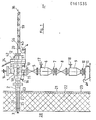
- a sampling container 1 is connected via a connecting piece 2 to a pressure vessel, in the example a fluidized bed pressure reactor 23, which an outer metallic reactor wall 21 and an inner wall lining 22 formed from insulating masonry is surrounded.
- the connecting piece 2 connects to a wall opening 63, which leads into the interior, the so-called process space, of the reactor 23, in which, in the example, a carbon water vapor fluidized bed 28 operated at a maximum of 850 ° C. and 40 bar is located.
- an insulating double tube 25 which contains a sampling tube 27 which serves as a piston cylinder for a sampling piston 3, with the aid of which the solid samples are removed from the fluidized bed 28.
- the sampling tube 27 extends into the sampling container 1.
- the piston rod 20 accommodated therein protrudes from the sampling container 1 and is guided in the outside area by a roller conveyor 19.
- An end flange 42 contains gas-tight 0-rings and an emergency stuffing box 12 through which the piston rod 20 is guided.
- the sampling container 1 is additionally secured by a holder 24.
- the piston rod 20 has at the end a guide eye 56, to which a winch rope 45 is attached, which leads to a winch 4, with the aid of which the reciprocating movement of the piston rod 20 can be controlled.
- the end position of the piston rod is denoted by 36, that is the position in which, as indicated in FIG. 1, the sampling piston 3 is in the discharge position above a discharge funnel 37 mounted in the sampling container 1.
- the sampling container 1 has a sealing gas space 34, into which the sampling tube 27 extends, which is closed at its end with a locking bush 33, which has a central opening for the piston 20.
- the sealing gas space 34 is supplied with sealing gas via a nozzle 13, which serves as a purge and cooling gas.
- Purge gas connectors 14, 15 and 16 are attached to the sample cream container 1, with which auxiliary purges can be carried out with the purge and cooling gas.
- the solids samples are discharged from the discharge funnel 37 via a first solids slide 5, a first sluice 6 with a gas press-on connector 17 and a first closure flap 7, and a second solids slide 8, a second sluice 9 with a gas expansion nozzle 18 and a second closure flap 10 which hold the solids sample in dispenses a collecting container 11 which is equipped with a hinged filter cover 61.
- All pressure-bearing parts are made from high-strength steel, in the present example from VA steel, and the parts that come into contact with high temperature are made from a heat-resistant steel, in the present example from Incoloy 800.
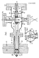
- Figures 2 and 3 show details of the design of the sampling part of the solid sampling device.
- the double insulating tube 25 is inserted into the flange 2 and welded tight to avoid bypass flows in the flange 2.
- the inner diameter of the double insulating tube 25 also serves as a sliding sleeve for the sampling tube 27.
- the latter is tightly welded and fixed in a flanged disk 39, which separates the sealing gas space 34 contained in the sampling container 1 from the rest of the container interior.
- Both the insulating double tube 25 and the sampling tube 27 can thus move freely in the direction of the process space (fluidized bed) 28 when temperature strains occur.
- the insulating double tube 25 is made with high-temperature-resistant Al 2 O 3 wool as the insulating filling 32 fills.
- the sampling piston 3 which is formed from a front piston ring 29 and a rear piston ring 30, is shown once in the sampling position and once in the discharge position.
- the removal piston 3 In the discharge position, the removal piston 3 is located in the area of the removal opening 59, which merges into the discharge funnel 37.
- a further opening is provided above the removal opening 59, which is closed by a hold-down device 26 which is guided on the connecting piece 14 and can be pressed onto the opening via a spring 38.
- additional flushing and cooling gas can be introduced into the container 1 or into the discharge area 59, 37, for example in order to prevent blockages that have occurred, via the connector 14, as is also the case via the connectors 15 and 16, and 40 and 41 to eliminate.
- the purge and cooling gas is supplied via the connector 13, it also serves as a sealing gas for the sealing and stuffing box area of the parts 12 and 33.
- the purge gas flows inside and outside the sampling tube 27 in the direction of the process space. It cools the solid sample, the sampling tube 27 and the piston rod 20. At the same time, it prevents solid particles from entering the gap between the insulating double tube 25 and the sampling tube 27, so that they cannot get jammed.
- the piston rod 20, which comes out during sampling, is sealed in front of the emergency stuffing box 12 via four 0-rings.
- the locking sleeve 33 forming the end of the sampling tube 27 is also packed with a high-temperature-resistant AI 0 - wool.
- the wool serves as a wiper pack against dust particles adhering to the piston rod 20.
- the cleaning process is supported by the blocking and cooling gas flowing counter to the packing.
- FIG. 2 also shows the sampling position of the sampling piston 3.
- a position is shown in which the piston only partially projects into the fluidized bed 28. However, it is also possible to actuate the piston rod 20 so that the removal piston 3 is completely immersed in the fluidized bed 28. This position is indicated by the dashed line of the rear piston 31.
- FIGS. 4 and 5 show details of the sampling device in the outer area.
- a holding plate 44 is attached to which two support brackets 43 are attached.
- the support brackets 43 carry a roller conveyor 47 in which rollers 53 are displaced, which serve to guide the piston rod 20 during the sampling process.
- the piston rod 20 emerges from the pressure range of the sampling device via an outer stuffing box 35, which is connected downstream of the inner stuffing box 12 via an end flange 48.
- the winch cable 45 is attached to a guide eye 56. Their back and forth movement can be controlled via the winch 4.
- the winch cable 45 like the piston rod 20, is also guided through the rollers 53.
- a guide groove 65 is provided for the winch rope 45.
- a counterweight 46 the rope 66 of which is also fastened to the eyelet 56, runs over an end roller 64.
- holding brackets 54 are attached to the roller conveyor support 47 and carry guide plates 55.
- FIGS. 6, 7 and 8 Various positions of the piston rod are shown in FIGS. 6, 7 and 8. During a full sample stroke (FIG. 6), a stop tab 51 strikes the end flange 48. In this position, the extraction piston 3 (FIG. 2) is completely in the fluidized bed 28.
- a spacer 52 is provided between the stop tab 51 and the end flange 48.
- FIG. 9 shows details of the removal piston 3 using an example.
- the two piston rings 29, 30 are each formed by five spaced-apart piston plates made of the high-temperature-resistant material Incoloy 800, the interspaces being filled by pressed insulating fiber mats 58 made of Al 2 O 3 .
- a series of punched, non-degressed holes 60 are provided in the piston surfaces 57 in order to provide the insulating fiber mats 58 with a firm fit. This design of the piston rings ensures that seizure of the piston is avoided by the solid particles being deposited in the soft, elastic insulating packing.
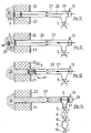
- FIGS. 11 to 14 The principle of sampling under pressure and temperature with the sampling device according to the invention is shown in FIGS. 11 to 14.
- Figure 11 shows the sampling piston 3 in the rest position.
- the front sealing piston 29 closes approximately flush with the lining 22.
- FIG. 12 shows the sampling process in which the sampling piston 3 is introduced into the fluidized bed 28.
- the piston is actuated by wind force.
- the flushing and cooling gas also prevents process gas and solids from entering the extraction tube 27 during this process.
- the tip 66 arranged on the piston 29 shows that, with appropriate training, sampling in a solid bed is also possible.
- FIG. 13 shows the sampling piston 3 in the sampling tube 27 with the solid sample 62 taken.
- the sampling piston 3 is pressed to the discharge point by the process pressure WP.
- the driving speed of the piston 20 is controlled via the winch 4.
- the driving speed is comparatively low at 1 to 2 cm / s.
- the solids-free part of the extraction tube 27 is under a pressure of flushing and cooling gas, so that no solid or process gas can escape from the extraction piston 3. Rather, the sample is cooled down by the countercurrent cooling and flushing gas (N 2 in the selected example) from approx. 850 ° C. fluidized bed temperature to approx. 8 ° C.
- the gaseous process partners are flushed back into the process room.
- the discharge process is shown in FIG.
- the extraction piston 3 is located above the lock funnel 37, into which the solid sample is first emptied. By opening the slide 5, the solid sample then passes into the first lock 6, from there via the second solid slide 8 into the second lock 9, from which the sample can then be withdrawn via the closure flap 10.
- the extraction piston 3 is moved back into the starting position with wind force (at 40 bar with approx. 80 kp).
- the solid that has flowed into the extraction tube 27 is pressed back into the process space 28. Since the solid on the circumference of the piston ring 29 is fluidized by the flushing and cooling gas escaping there, this cleaning process can be carried out without jamming the piston rings 29, 30.
- the tried-and-tested lock size allows a recoverable sample amount of approx. 1100 ml of solid.
- the sample is obtained in ten shift cycles and then discharged. The time required for this is approximately 20 minutes. For urgent C determinations, it takes approx. 6 minutes to discharge a cycle with approx. 110 ml sample material.
- Table 1 shows the grain change during a batch reactor test. With increasing gasification up to a degree of gasification of 56%, the average grain increases three times. The grain disintegrates again as gasification proceeds. With a degree of gasification of 84%, the average grain found was 0.39 mm in this test. The findings apply to the location of the sampling in the fluidized bed.
- Table 2 shows the differences in the grain distribution between a direct sample from the fluidized bed and a sample from the ash area for the same test period.
- the average grain size of the insert coal was 0.31 mm and the bulk density 762 kg / m 3 for Westerholt gas flame coal.
- the mean grain of the direct sample from the fluidized bed was 0.53 mm and the bulk density 160.8 kg / m 3
- the mean grain of the sample from the ash area was 0.36 mm and the bulk weight 480 kg / m 3 .
- the degree of gasification was 68% and the flow velocity was 9.8 cm / s.
- the catalyst addition was 4% K 2 CO 3 .
- the amount of sample that can be obtained depends on the piston and lock size.
- the piston movement can be motor-driven and the lock system can be controlled by a control program. Any working direction of the piston is possible from vertical to horizontal. Sealing elements for the cooled sealing area in the form of 0-rings or lip seals are state of the art.
- the extraction flask working in the high temperature range could be made of ceramic material at very high temperatures ( ⁇ 1300 ° C).
- the piston rod would expediently be cooled from the inside.
- the piston front as indicated in FIGS. 11 to 14, would have to be of a tapered slim design, so that easier penetration into the bed is ensured.
Landscapes
- Life Sciences & Earth Sciences (AREA)
- Hydrology & Water Resources (AREA)
- Physics & Mathematics (AREA)
- Health & Medical Sciences (AREA)
- Chemical & Material Sciences (AREA)
- Analytical Chemistry (AREA)
- Biochemistry (AREA)
- General Health & Medical Sciences (AREA)
- General Physics & Mathematics (AREA)
- Immunology (AREA)
- Pathology (AREA)
- Sampling And Sample Adjustment (AREA)
Abstract
Description
- Die Erfindung betrifft eine Entnahmevorrichtung für Feststoffproben aus einem Druckreaktor.
- Bei chemischen und physikalischen Prozessen, insbesondere bei Pyrolyse- und Vergasungsvorgängen, die in druckbetriebenen Wirbelschichtreaktoren ablaufen, sind Kenntnisse über die chemische und physikalische Veränderung des Korns, z.B. des Kohlekorns in der Wirbelschicht erwünscht, weil insbesondere das hydrodynamische Verhalten der Wirbelschicht durch Korngrößenänderungen beeinflußt wird. Derartige Untersuchungen sind bisher nur im Labormaßstab durchgeführt worden.
- Der Erfindung liegt die Aufgabe zugrunde, repräsentative Feststoffproben unmittelbar aus der betriebenen heißen Wirbelschicht zu entnehmen, wobei die Probe in ihrer Feststoffsubstanz chemisch und physikalisch unverfälscht und im Kornaufbau unbeschädigt anfallen soll.
- Diese Aufgabe wird durch die im Kennzeichen des Anspruchs 1 beschriebenen Merkmale gelöst.
- Zweckmäßige Weiterbildungen und Ausgestaltungen sind in den Unteransprüchen dargestellt.
- Mit der erfindungsgemäßen Entnahmevorrichtung gelingt es, heiße Feststoffproben, die noch aggressive Rohgasanteile enthalten, auf ihrem Transportweg vom Druckeaktor zur Ausschleusstelle von dem aggressiven Rohgasanteil durch Spülen zu befreien und`dabei gleichzeitig zu kühlen. In Ruhestellung verhindert ständig strömendes Spülgas das Eindringen von Rohgas und Feststoffpartikeln in den Entnahmekolben. Beim Zurückfahren des Entnahmekolbens, das vorzugsweise mittels Windenkraft geschieht, wird der im Probeentnahmerohr nachgeflossene Feststoff in den Prozeßraum zurückgedrückt, was durch den ständigen Spülvorgang problemlos möglich ist.
- Zweckmäßig werden die Entnahmekolben aus mehreren Kolbenblechen hergestellt, zwischen denen gasdurchlässige Isolierschichten angeordnet sind.
- Als Wärmeschutz empfiehlt es sich, das Probeentnahmerohr im Reaktorwandbereich in einem mit Isoliermaterial gefüllten Doppelrohr zu führen, in dem daneben Spül- und Kühlgas umläuft.
- Zweckmäßig wird auch das Probeentnahmerohr am Ende durch eine Isolierbuchse verschlossen.
- Vorzugsweise ist die Kolbenstange über 0-Ringe und eine Not-Stopfbuchse aus dem Probenahmebehälter herausgeführt und auf einer Rollenbahn verlagert, wobei die Kolbenbewegung über eine außerhalb angebrachte Winde durchgeführt und gesteuert wird.
- Die Ausschleusvorrichtung für die Feststoffproben besteht zweckmäßig aus einem Ausschleustrichter im Probeentnahmebehälter, aus dem die Feststoffprobe über ein doppeltes Schleusensystem in den Auffangbehälter gelangt.
- Die Erfindung wird nachfolgend anhand der Zeichnung beispielhaft beschrieben. Es zeigen:
- Figur 1 eine Übersichtsdarstellung der Entnahmevorrichtung für Feststoffproben;
- Figur 2 eine Schnittdarstellung des Probeentnahmerohres und des Probenahmebehälters;
- Figur 3 einen Querschnitt A-B des Probeausschleusbereichs im Probenahmebehälter;
- Figur 4 eine Darstellung der Rollenbahn für die Kolbenstange;
- Figur 5 einen Querschnitt C-D der Rollenbahn;
- Figur 6 eine Teilansicht mit der Kolbenstellung im Bereich der Rollenbahn für einen Probenhub von 85 mm;
- Figur 7 den Gegenstand der Figur 6 für einen Probenhub von 35 mm;
- Figur 8 den Gegenstand der Figur 6 in Ruhestellung;
- Figur 9 einen Längsschnitt des Entnahmekolbens;
- Figur 10 die Ansicht eines Kolbenbleches des Entnahmekolbens;
- Figur 11 bis 14 das Prinzip der Probeentnahme mit der erfindungsgemäßen Entnahmevorrichtung für Feststoffproben unter Druck und Temperatur; wobei
- Figur 11 die Ruhestellung des Entnahmekolbens,
- Figur 12 die Probeentnahmestellung des Kolbens,
- Figur 13 die Hubbewegung zum Ausschleusbereich und
- Figur 14 den Entnahmekolben in Ausschleusstellung wiedergeben.
- Aus Figur 1 gehen Aufbau und Prinzip der Entnahmevorrichtung für Feststoffproben hervor. Ein Probeentnahmebehälter 1 ist über einen Anschlußstutzen 2 mit einem Druckbehälter, im Beispiel einen Wirbelschichtdruckreaktor 23 verbunden, der von einer äußeren metallischen Reaktorwand 21 und einer inneren, aus Isoliermauerwerk gebildeten Wandauskleidung 22 umgeben ist. Der Anschlußstutzen 2 schließt an eine Wandöffnung 63 an, die bis in den Innenraum, den sogenannten Prozeßraum, des Reaktors 23 führt, in dem sich im Beispiel ein unter maximal 850°C und 40 bar betriebenes Kohlewasserdampf-Wirbelbett 28 befindet.
- In der Wandöffnung 63 ist ein Isolierdoppelrohr 25 angeordnet, das ein Probeentnahmerohr 27 enthält, das als Kolbenzylinder für einen Entnahmekolben 3 dient, mit dessen Hilfe die Feststoffproben aus dem Wirbelbett 28 entnommen werden.
- Das Probeentnahmerohr 27 reicht bis in den Probeentnahmebehälter 1 hinein. Die darin untergebrachte Kolbenstange 20 ragt aus dem Probeentnahmebehälter 1 heraus und wird im Außenbereich von einer Rollenbahn 19 geführt. Ein Endflansch 42 enthält gasdichte 0-Ringe und eine Not-Stopfbuchse 12, durch die hindurch die Kolbenstange 20 geführt ist. Der Probeentnahmebehälter 1 wird zusätzlich durch eine Halterung 24 abgesichert.
- Die Kolbenstange 20 weist am Ende eine Führungsöse 56 auf, an die ein Windenseil 45 angeschlagen ist, das zu einer Winde 4 führt, mit deren Hilfe die Hin- und Herbewegung der Kolbenstange 20 gesteuert werden kann. Die Endstellung der Kolbenstange ist mit 36 bezeichnet, das ist die Stellung, in der, wie in Figur 1 angedeutet, der Entnahmekolben 3 in Ausschleusstellung über einem in dem Probeentnahmebehälter 1 montierten Ausschleustrichter 37 steht.
- Der Probeentnahmebehälter 1 weist einen Sperrgasraum 34 auf, bis in den hinein das Probeentnahmerohr 27 reicht, das an seinem Ende mit einer Sperrbuchse 33 verschlossen ist, die mittig eine Durchgangsöffnung für den Kolben 20 aufweist.
- Der Sperrgasraum 34 wird über einen Stutzen 13 mit Sperrgas beaufschlagt, das als Spül- und Kühlgas dient.
- Am Probenahnebehälter 1 sind Spülgasstutzen 14, 15 und 16 angebracht, mit denen Hilfsspülungen mit dem Spül- und Kühlgas durchgeführt werden können.
- Das Ausschleusen der Feststoffproben aus dem Ausschleustrichter 37 geschieht über einen ersten Feststoffschieber 5, eine erste Schleuse 6 mit Gasaufdrückstutzen 17 und einer ersten Verschlußklappe 7 sowie einem zweiten Feststoffschieber 8, einer zweiten Schleuse 9 mit Gasentspannstutzen 18 und einer zweiten Verschlußklappe 10, die die Feststoffprobe in einen Auffangbehälter 11 abgibt, der mit einem aufklappbaren Filterdeckel 61 ausgestattet ist.
- Alle drucktragenden Teile sind aus hochfestem Stahl, im vorliegenden Beispiel aus VA-Stahl, gefertigt und die mit Hochtemperatur in Kontakt tretenden Teile aus einem warmfesten Stahl, im vorliegenden Beispiel aus Incoloy 800, gefertigt.
- Die Figuren 2 und 3 zeigen Einzelheiten der Ausgestaltung des Probenahmeteils der Feststoffprobenahmevorrichtung. Das Isolierdoppelrohr 25 ist bis in den Flansch 2 hineingeführt und zur Vermeidung von Bypaßströmungen im Flansch 2 dichtgeschweißt. Der innere Durchmesser des Isolierdoppelrohres 25 dient gleichzeitig als Gleithülse für das Probeentnahmerohr 27. Letzteres ist in einer Bordscheibe 39 dichtgeschweißt und fixiert, die den im Probenahmebehälter 1 enthaltenen Sperrgasraum 34 vom übrigen Behälterinneren abtrennt. Sowohl das Isolierdoppelrohr 25 als auch das Probeentnahmerohr 27 können sich somit frei in Richtung Prozeßraum (Wirbelbett) 28 bewegen, wenn Temperaturdehnungen auftreten. Im Beispiel ist das Isolierdoppelrohr 25 mit hochtemperaturfester Al2O3-Wolle als Isolierfüllung 32 ausgefüllt. In der Figur 2 ist der Entnahmekolben 3, der aus einem vorderen Kolbenring 29 und aus einem hinteren Kolbenring 30 gebildet ist, einmal in Probenahmestellung und einmal in Ausschleusstellung abgebildet. In Ausschleusstellung befindet sich der Entnahmekolben 3 im Bereich der Entnahmeöffnung 59, die in den Ausschleustrichter 37 übergeht. Oberhalb der Entnahmeöffnung 59 ist eine weitere Öffnung vorgesehen, die durch einen Niederhalter 26 verschlossen ist, der auf dem Stutzen 14 geführt und über eine Feder 38 auf die Öffnung preßbar ist. Über den Stutzen 14, wie übrigens auch über die Stutzen 15 und 16, sowie 40 und 41, kann, wie bereits erwähnt, zusätzlich Spül- und Kühlgas in den Behälter 1 bzw. in den Ausschleusbereich 59, 37 aufgegeben werden, etwa um aufgetretene Verstopfungen zu beseitigen. Im Normalfall erfolgt die Aufgabe des Spül- und Kühlgases über den Stutzen 13, es dient gleichzeitig als Sperrgas für den Dichtungs- und Stopfbuchsenbereich der Teile 12 und 33. Das Spülgas strömt innerhalb und außerhalb des Probeentnahmerohres 27 in Richtung auf den Prozeßraum zu. Es kühlt dabei die Feststoffprobe, das Probeentnahmerohr 27 und die Kolbenstange 20. Gleichzeitig verhindert es das Eindringen von Feststoffpartikeln in den Spalt zwischen dem Isolierdoppelrohr 25 und dem Probeentnahmerohr 27, damit sich diese nicht verklemmen können.
- Die bei der Probenahme nach außen tretende Kolbenstange 20 wird vor der Not-Stopfbuchse 12 über vier 0-Ringe abgedichtet.
- Die den Abschluß des Probeentnahmerohres 27 bildende Sperrbuchse 33 ist ebenfalls mit einer hochtemperaturfesten AI 0--Wolle gepackt. Die Wolle dient als Abstreifpackung gegenüber an der Kolbenstange 20 anhaftenden Staubpartikeln. Der Säuberungsvorgang wird durch das in der Packung gegenströmende Sperr- und Kühlgas unterstützt.
- In der Figur 2 ist außerdem die Probenahmestellung des Entnahmekolbens 3 dargestellt. Abgebildet ist eine Stellung, in der der Kolben nur teilweise in die Wirbelschicht 28 hineinragt. Es ist aber auch möglich, die Kolbenstange 20 so zu betätigen, daß der Entnahmekolben 3 vollständig in die Wirbelschicht 28 eintaucht. Diese Stellung ist durch die strichlierte Darstellung des hinteren Kolbens 31 angedeutet.
- In den Figuren 4 und 5 sind Einzelheiten der Probenahmevorrichtung im Außenbereich dargestellt. Am Endflansch 42 des Probeentnahmebehälters 1 ist eine Halteplatte 44 befestigt, an der zwei Tragkonsolen 43 angebracht sind. Die Tragkonsolen 43 tragen einen Rollenbahnträger 47, in dem Rollen 53 verlagert sind, die zur Führung der Kolbenstange 20 während des Probenahmevorganges dienen. Die Kolbenstange 20 tritt über eine äußere Stopfbuchse 35, die über einen Endflansch 48 der inneren Stopfbuchse 12 nachgeschaltet ist, aus dem Druckbereich der Probeentnahmevorrichtung heraus. Am Ende der Kolbenstange 20 ist das Windenseil 45 an einer Führungsöse 56 angeschlagen. Ihre Hin- und Herbewegung ist über die Winde 4 steuerbar. Auch das Windenseil 45 wird wie die Kolbenstange 20 durch die Rollen 53 geführt. Für das Windenseil 45 ist eine Führungsnut 65 vorgesehen. Ein Gegengewicht 46, dessen Seil 66 ebenfalls an der Öse 56 befestigt ist, läuft über eine Endrolle 64. Zur Verstärkung der Pollenbahn und gleichzeitig als Führung für die Führungsöse 56 sind an den Rollenbahnträger 47 Haltewinkel 54 angebracht, die Führungslaschen 55 tragen.
- In den Figuren 6, 7 und 8 sind verschiedene Stellungen der Kolbenstange dargestellt. Bei einem vollen Probenhub (Figur 6) schlägt eine Anschlaglasche 51 an den Endflansch 48 an. In dieser Stellung befindet sich der Entnahmekolben 3 (Figur 2) vollständig in der Wirbelschicht 28.
- Bei einem verkürzten Probenhub (Figur 7) ist ein Distanzstück 52 zwischen Anschlaglasche 51 und Endflansch 48 vorgesehen.
- In Figur 8 ist die Ruhestellung des Entnahmekolbens abgebildet, während der der Kolben 20 dadurch stillgesetzt wird, daß die Anschlaglasche 51 an der Kolbenstange 20 an eine Anschlaglasche 50 angeschlagen wird, die über eine Traglasche 49 am Endflansch 48 befestigt ist.
- Figur 9 zeigt an einem Beispiel Einzelheiten des Entnahmekolbens 3. Die beiden Kolbenringe 29, 30 werden durch je fünf im Abstand voneinander angeordnete Kolbenbleche aus dem hochtemperaturbeständigen Werkstoff Incoloy 800 gebildet, wobei die Zwischenräume durch gepreßt eingelegte Isolierfasermatten 58 aus Al203 ausgefüllt sind. In den Kolbenflächen 57 sind eine Reihe von geschlagenen, nicht entgradeten Löchern 60 vorgesehen, um den Isolierfasermatten 58 einen festen Sitz zu verschaffen. Diese Ausgestaltung der Kolbenringe gewährleistet, daß ein Festfressen des Kolbens dadurch vermieden wird, daß sich die Feststoffpartikel in der weichen elastischen Isolierpackung ablagern.
- Das Prinzip der Probeentnahme unter Druck und Temperatur mit der erfindungsgemäßen Probeentnahmevorrichtung ist in den Figuren 11 bis 14 dargestellt.
- Figur 11 zeigt den Entnahmekolben 3 in Ruhestellung. Dabei schließt der vordere Dichtkolben 29 in etwa bündig mit der Ausmauerung 22 ab". Das über den Stutzen 13 eingetragene Spül-und Kühlgas, das einen geringen Überdruck gegenüber dem Innendruck des Wirbelbettes 28 aufweist, verhindert, daß weder Prozeßgas noch Feststoffpartikel in das Entnahmerohr 27 gelangen.
- Figur 12 zeigt den Vorgang der Probenahme, bei der der Entnahmekolben 3 in die Wirbelschicht 28 eingeführt wird. Die Kolbenbetätigung erfolgt dabei durch Windenkraft. Das Spül-und Kühlgas verhindert auch bei diesem Vorgang, daß Prozeßgas und Feststoffe in das Entnahmerohr 27 eindringen.
- Die an dem Kolben 29 angeordnete Spitze 66 zeigt auf, daß bei entsprechender Ausbildung auch eine Probenahme in einer Feststoffschüttung möglich ist.
- Figur 13 zeigt den Entnahmekolben 3 im Entnahmerohr 27 mit der genommenen Feststoffprobe 62. Der Entnahmekolben 3 wird durch den Prozeßdruck WP zur Ausschleusstelle gedrückt. Die Fahrgeschwindigkeit des Kolbens 20 wird dabei über die Winde 4 gesteuert. Die Fahrgeschwindigkeit ist mit 1 bis 2 cm/s vergleichsweise gering. Auch während des Bewegungsvorganges ist der feststofffreie Teil des Entnahmerohres 27 unter Spül- und Kühlgasüberdruck, so daß kein Feststoff oder Prozeßgas aus dem Entnahmekolben 3 austreten kann. Vielmehr wird die Probe durch das gegenströmende Kühl- und Spülgas (N2 im gewählten Beispiel) von ca. 850°C Wirbelschichttemperatur auf ca. 8°C heruntergekühlt. Die gasförmigen Prozeßpartner werden dabei in den Prozeßraum zurückgespült.
- In Figur 14 ist der Ausschleusvorgang dargestellt. Der Entnahmekolben 3 befindet sich über dem Schleusentrichter 37, in den die Feststoffprobe zunächst entleert wird. Durch Öffnen des Schiebers 5 gelangt die Feststoffprobe anschließend in die erste Schleuse 6, von dort über den zweiten Feststoffschieber 8 in die zweite Schleuse 9, woraus die Probe dann über die Verschlußklappe 10 abgezogen werden kann.
- Anschließend wird der Entnahmekolben 3 mit Windenkraft (bei 40 bar mit ca. 80 kp) wieder in die Ausgangsstellung gefahren. Dabei wird der in das Entnahmerohr 27 nachgeflossene Feststoff in den Prozeßraum 28 zurückgedrückt. Da der Feststoff am Umfang des Kolbenringes 29 durch das dort austretende Spül- und Kühlgas fluidisiert wird, läßt sich dieser Säuberungsvorgang ohne Verklemmen der Kolbenringe 29, 30 durchführen.
- Die beschriebene Feststoff-Probeentnahmevorrichtung wurde für einen Nenndruck von PN = 64 bar und eine Nennweite von DN = 50 mm 0 ausgelegt und am Gasgenerator einer halbtechnischen Kohlevergasungsanlage montiert. Während des Vergasungsbetriebes wurden bislang ca. hundert Feststoffproben aus dem Prozeßraum, d.h. einem unter max. 8500C und 40 bar betriebenen Kohle-Wasserdampfwirbelbett, störungsfrei gezogen. Die erprobte Schleusengröße läßt eine gewinnbare Probenmenge von ca. 1100 ml Feststoff zu. Die Probe wird in zehn Schiebezyklen gewonnen und dann ausgeschleust. Die erforderliche Zeit dazu beträgt ca. 20 Minuten. Für eilige C-Bestimmungen benötigt man für das Ausschleusen eines Zyklus mit ca. 110 ml Probenmaterial ca. 6 Minuten.
- Die eingestellte Spül- und Kühlgasmenge beträgt 3 m3 N/h N2. Damit stellen sich folgende Leerrohr-Strömungsgeschwindigkeiten am Entnahmekolben ein:

- Zu a) Die im Kolbenbereich eingestellte Strömungsgeschwindigkeit von 46 cm/s = 2,3-fache Lockerungsgeschwindigkeit garantiert durch den "fluidisierten Kolben" ein störungsfreies Zurückschieben des eingeflossenen Wirbelbettgutes. (An gezogenen Gasflammmkohle-Wirbelbettproben wurde die einfache Lockerungsgeschwindigkeit ermittelt. Sie lag mit Luft angeströmt bei ca. 20 cm/s. Bei ca. 38 cm/s erfolgte totale Fluidisierung der Probe.)
- Zu b) Bei 1 cm/s Strömungsgeschwindigkeit im Doppelkolb.en- bereich erfolgt in der Probe fast keine Kornbewegung und somit kein Austrag von Feinstkorn.
- Ermittelte Ergebnisse an Probenmaterial aus dem Wirbelbett (40 bar, max. 850°C).
- Beispielhaft werden im folgenden einige Untersuchungen bezüglich der Korngrößenveränderung mitgeteilt.
- Tabelle 1 zeigt die Kornveränderung während eines Satzreaktorversuches. Mit zunehmender Vergasung bis zu einem Vergasungsgrad von 56 % vergrößert sich das mittlere Korn um das 3-fache. Bei weiter fortschreitender Vergasung zerfällt das Korn wieder. Bei einem Vergasungsgrad von 84 % beträgt das mittlere festgestellte Korn 0,39 mm bei diesem Versuch. Die Feststellungen gelten für den Ort der Probenahme im Wirbelbett.
- Tabelle 2 zeigt auf, welche Unterschiede in der Kornverteilung zwischen einer direkt gezogenen Probe aus dem Wirbelbett und einer Probe aus dem Aschebereich für den gleichen Versuchszeitraum auftreten.

- Danach betrug das mittlere Korn der Einsatzkohle 0,31 mm und das Schüttgewicht 762 kg/m3 für Gasflammkohle Westerholt. Das mittlere Korn der direkten Probe aus dem Wirbelbett betrug 0,53 mm und das Schüttgewicht 160,8 kg/m3, dagegen das mittlere Korn der Probe aus dem Aschebereich 0,36 mm und das Schüttgewicht 480 kg/m3.
- Bei diesen Versuchen lag der Vergasungsgrad bei 68 % und die Anströmgeschwindigkeit bei 9,8 cm/s. Die Katalysatorzugabe betrug 4 % K2CO3.

-
- 1 Probeentnahmebehälter
- 2 Anschlußstutzen
- 3 Entnahmekolben
- 4 Winde
- 5 erster Feststoffschieber
- 6 erste Schleuse
- 7 erste Verschlußklappe
- 8 zweiter Feststoffschieber
- 9 zweite Schleuse
- 10 zweite Verschlußklappe
- 11 Auffangbehälter
- 12 Stopfbuchse
- 13 Stutzen (Sperrgas, Stopfbuchse)
- 14 Spülgasstutzen (Hilfsspülung)
- 15 " "
- 16 " "
- 17 Gasaufdrückstutzen
- 18 Gasentspannstutzen
- 19 Rollenbahn
- 20 Kolbenstange
- 21 Reaktor
- 22 Wandauskleidung
- 23 Wirbelschichtdruckreaktor
- 24 Halterung
- 25 Isolierdoppelrohr
- 26 Niederhalter
- 27 Probeentnahmerohr
- 28 Wirbelbett
- 29 vorderer Dichtkolben
- 30 hinterer Dichtkolben 1. Stellung
- 31 hinterer Dichtkolben 2. Stellung
- 32 Isolierfüllung
- 33 Sperrbuchse
- 34 Sperrgasraum
- 35 äußere Isolierbuchse
- 36 Kolbenendstellung
- 37 Ausschleustrichter
- 38 Federelement
- 39 Bordscheibe
- 40 Hilfsspülstutzen
- 41 "
- 42 Endflansch
- 43 Tragkonsole
- 44 Halteplatte
- 45 Windenseil
- 46 Gegengewicht
- 47 Rollenbahnträger
- 48 Endflansch
- 49 Traglasche
- 50 Anschlaglasche
- 51 Anschlaglasche
- 52 Distanzstück
- 53 Rolle
- 54 Haltewinkel
- 55 Führungslasche
- 56 Führungsöse
- 57 Kolbenblech
- 58 Isolierfasermatten
- 59 Entnahmeöffnung
- 60 geschlagene, nicht entgratete Löcher
- 61 klappbare Filterdeckel
- 62 Feststoffprobe
- 63 Wandöffnung
- 64" Endrollen
- 65 Führungsnut
- 66 Eindrückkegel
Claims (6)
Applications Claiming Priority (2)
| Application Number | Priority Date | Filing Date | Title |
|---|---|---|---|
| DE3418311A DE3418311A1 (de) | 1984-05-17 | 1984-05-17 | Entnahmevorrichtung fuer feststoffproben |
| DE3418311 | 1984-05-17 |
Publications (3)
| Publication Number | Publication Date |
|---|---|
| EP0161535A2 true EP0161535A2 (de) | 1985-11-21 |
| EP0161535A3 EP0161535A3 (en) | 1986-12-03 |
| EP0161535B1 EP0161535B1 (de) | 1989-06-21 |
Family
ID=6236101
Family Applications (1)
| Application Number | Title | Priority Date | Filing Date |
|---|---|---|---|
| EP85104796A Expired EP0161535B1 (de) | 1984-05-17 | 1985-04-20 | Entnahmevorrichtung für Feststoffproben |
Country Status (4)
| Country | Link |
|---|---|
| US (1) | US4630479A (de) |
| EP (1) | EP0161535B1 (de) |
| DE (2) | DE3418311A1 (de) |
| ZA (1) | ZA853466B (de) |
Cited By (1)
| Publication number | Priority date | Publication date | Assignee | Title |
|---|---|---|---|---|
| EP1516660A3 (de) * | 2003-09-19 | 2005-04-13 | GE Jenbacher GmbH & Co. OHG | Adsorbereinrichtung |
Families Citing this family (15)
| Publication number | Priority date | Publication date | Assignee | Title |
|---|---|---|---|---|
| DE4023841A1 (de) * | 1990-07-27 | 1992-02-06 | Wiederaufarbeitung Von Kernbre | Einrichtung zur entnahme von gas- und/oder fluessigkeitsproben aus einem sicherheitsbehaelter von kernkraftwerken |
| JP3037576B2 (ja) * | 1995-01-26 | 2000-04-24 | コーエイ工業株式会社 | 濾液測定方法およびその装置 |
| US6164145A (en) * | 1998-12-23 | 2000-12-26 | Jaeger; Ben E. | Liquid sample and method |
| US6055870A (en) * | 1999-06-22 | 2000-05-02 | Jaeger; Ben E. | Sampler for fluidized product |
| US6886420B2 (en) * | 2001-02-01 | 2005-05-03 | Rhe Haendel Engineering Gmbh & Co Kg | Sampling apparatus |
| US6807873B2 (en) * | 2002-02-27 | 2004-10-26 | Ben E. Jaeger | Dry material sampler and method |
| KR100653254B1 (ko) | 2005-07-01 | 2006-12-01 | 삼성토탈 주식회사 | 고정층 베드의 입자 샘플링 기구 |
| WO2012012896A1 (en) * | 2010-07-24 | 2012-02-02 | Clayton Hoffarth | Downhole pump with a pressure sequencing valve |
| DE112012001407A5 (de) * | 2011-03-24 | 2013-12-19 | Hochschule Merseburg | Vorrichtung und Verfahren zur Verweilzeitsteuerung bei einer katalytischen Umsetzung von feststoffhaltigen Kohlenwasserstoffen |
| BR112017012963A2 (pt) * | 2014-12-19 | 2018-03-06 | Hollison Llc | sistema e método de realimentação para avaliação oportuna de uma condição de materiais a granel |
| CN107860680B (zh) * | 2017-12-19 | 2020-07-03 | 武汉钢铁有限公司 | 一种高炉风口焦粒度组成和渣滞留量的分析方法 |
| CN114778199B (zh) * | 2022-04-18 | 2023-03-24 | 徐州汉晨机械制造有限公司 | 一种海洋地质环境勘探取样器及取样方法 |
| LU103213B1 (de) * | 2023-11-10 | 2025-05-12 | Thyssenkrupp Ag | Probennehmer für einen Oxyfuel-Prozess |
| WO2025099107A1 (de) | 2023-11-10 | 2025-05-15 | thyssenkrupp Polysius GmbH | Probennehmer für einen oxyfuel-prozess |
| CN118961269B (zh) * | 2024-10-16 | 2024-12-10 | 中国林业科学研究院资源信息研究所 | 一种生物质热解炭化试验用冷却分层取样装置 |
Family Cites Families (15)
| Publication number | Priority date | Publication date | Assignee | Title |
|---|---|---|---|---|
| DE394679C (de) * | 1923-04-22 | 1924-05-03 | Karl Biewald | Stoffprobenentnehmer fuer Zellstoffkocher |
| US2615339A (en) * | 1947-11-21 | 1952-10-28 | Holge Sigbjorn Paul Ebbinghaus | Apparatus for sampling pulp |
| US3129590A (en) * | 1961-03-03 | 1964-04-21 | California Research Corp | Particulate solid sampling device |
| DE1215962B (de) * | 1963-12-13 | 1966-05-05 | Polysius Gmbh | Probenehmer |
| FR1527039A (fr) * | 1967-04-10 | 1968-05-31 | Siderurgie Fse Inst Rech | Dispositif de prélèvement automatique d'échantillons dans un bain liquide |
| US3487695A (en) * | 1968-06-12 | 1970-01-06 | Chevron Res | Gas lift catalyst sampler |
| US3541860A (en) * | 1969-03-18 | 1970-11-24 | Goodyear Tire & Rubber | Pressure vessel sampling device |
| DE1934028A1 (de) * | 1969-07-04 | 1971-01-14 | Hartmann & Braun Ag | Wassergekuehlte Gasentnahmevorrichtung zur Entnahme sehr heisser Rauchgase fuer gasanalytische Zwecke |
| US3643508A (en) * | 1969-12-15 | 1972-02-22 | Dango & Dienenthal Kg | Device for removing gas and furnace charge probes from shaft furnaces and/or for taking temperature and gas pressure measurements in the interior space of the furnace |
| SE335021B (de) * | 1970-03-04 | 1971-05-10 | Kaelle Regulatorer Ab | |
| BE822079A (fr) * | 1973-11-29 | 1975-03-03 | Preleveur volumetrique d'echantillons de matiere fluide | |
| GB1491099A (en) * | 1975-02-17 | 1977-11-09 | Continental Oil Co | Reactor sampler |
| US4262533A (en) * | 1979-05-03 | 1981-04-21 | Jaeger Ben E | Heated liquid sampler |
| US4355539A (en) * | 1980-12-30 | 1982-10-26 | Mobil Oil Corporation | Fluid sampling probe |
| US4433587A (en) * | 1983-01-17 | 1984-02-28 | Gustafson, Inc. | Sampler for flowing pressurized dry material |
-
1984
- 1984-05-17 DE DE3418311A patent/DE3418311A1/de not_active Withdrawn
-
1985
- 1985-04-20 DE DE8585104796T patent/DE3571156D1/de not_active Expired
- 1985-04-20 EP EP85104796A patent/EP0161535B1/de not_active Expired
- 1985-05-08 ZA ZA853466A patent/ZA853466B/xx unknown
- 1985-05-17 US US06/735,415 patent/US4630479A/en not_active Expired - Fee Related
Cited By (1)
| Publication number | Priority date | Publication date | Assignee | Title |
|---|---|---|---|---|
| EP1516660A3 (de) * | 2003-09-19 | 2005-04-13 | GE Jenbacher GmbH & Co. OHG | Adsorbereinrichtung |
Also Published As
| Publication number | Publication date |
|---|---|
| EP0161535B1 (de) | 1989-06-21 |
| DE3418311A1 (de) | 1985-11-21 |
| DE3571156D1 (en) | 1989-07-27 |
| EP0161535A3 (en) | 1986-12-03 |
| ZA853466B (en) | 1985-12-24 |
| US4630479A (en) | 1986-12-23 |
Similar Documents
| Publication | Publication Date | Title |
|---|---|---|
| EP0161535B1 (de) | Entnahmevorrichtung für Feststoffproben | |
| DD256373A5 (de) | Verfahren und Vorrichtung zur kontinuierlichen Entnahme einer heißen Gasprobe aus einem Reaktionsraum für eine Gasanalyse | |
| DE2442836A1 (de) | Katalysatorueberfuehrungsverfahren fuer bewegtbett-reaktoren | |
| EP0215857A1 (de) | Verfahren zum ausschleusen von rückstandspartikeln aus einem druckvergasungsreaktor. | |
| DE69833040T2 (de) | Bestimmung des schmelzflussindexes bei der polymerisationsüberwachung | |
| DE102009036119A1 (de) | Verfahren und Vorrichtung zur Kühlung eines feinkörnigen Feststoffes bei gleichzeitigem Austausch des darin enthaltenen Lückenraumgases | |
| DE3137586C2 (de) | ||
| EP0278287B1 (de) | Verfahren und Einrichtung zur Behandlung von körnigen Feststoffen in einer Wirbelschicht | |
| AT523861B1 (de) | Vorrichtung zum sammeln von staubproben | |
| DE102008025877A1 (de) | Vorrichtung zur Bestimmung des Gehalts an mindestens einem oxidierbaren Inhaltsstoff in einer wässrigen Flüssigkeitsprobe | |
| DE68902602T2 (de) | Synthesegaskuehler mit thermischer abschirmung. | |
| DE1642918C3 (de) | Verfahren und Vorrichtung zum Dosieren eines pulverförmigen Gutes | |
| DE2615279C3 (de) | Verfahren zur Überführung einer Katalysatorprobe definierter Größe | |
| DE3008741C2 (de) | Vorrichtung für die Pyrolyse von Müll | |
| DE2909647C2 (de) | Verfahren und Vorrichtung zur Reinigung von Gichtgas | |
| DE60126064T2 (de) | Verfahren und vorrichtung zum verpacken von ultrafeinem pulver in behälter | |
| DE202011102526U1 (de) | Reaktorbehälter | |
| DE19843255A1 (de) | Verfahren und Vorrichtung zum Eintragen körniger Feststoffe in Drucksysteme oder -reaktoren | |
| EP0252169A1 (de) | Verfahren und Vorrichtung zur Druckregelung und unter Druck stehender Faulbehälter bei Biogasanlagen sowie Reinigung des Biogases in zwei Stufen | |
| DE19522596C2 (de) | Vorrichtung zur Rückgewinnung und/oder Reinigung von kontaminierten Schmierölen | |
| DE2617490A1 (de) | Verfahren und vorrichtung zur zufuehrung von trockenem, fliessfaehigem kohlenstaub in einen hochdruck-kohlevergasungsreaktor | |
| DE3422676A1 (de) | Drehbrennvorrichtung | |
| DE102008035604A1 (de) | Vorrichtung und Verfahren zur Entgasung von Stäuben | |
| DE1767364C (de) | Vorrichtung zur Regenerierung eines Ka talysators Ausscheidung aus 1667308 | |
| DE2950731C2 (de) | Vorrichtung zum Reinigen eines Gases |
Legal Events
| Date | Code | Title | Description |
|---|---|---|---|
| PUAI | Public reference made under article 153(3) epc to a published international application that has entered the european phase |
Free format text: ORIGINAL CODE: 0009012 |
|
| AK | Designated contracting states |
Designated state(s): DE FR GB |
|
| PUAL | Search report despatched |
Free format text: ORIGINAL CODE: 0009013 |
|
| AK | Designated contracting states |
Kind code of ref document: A3 Designated state(s): DE FR GB |
|
| 17P | Request for examination filed |
Effective date: 19861216 |
|
| 17Q | First examination report despatched |
Effective date: 19880418 |
|
| GRAA | (expected) grant |
Free format text: ORIGINAL CODE: 0009210 |
|
| AK | Designated contracting states |
Kind code of ref document: B1 Designated state(s): DE FR GB |
|
| GBT | Gb: translation of ep patent filed (gb section 77(6)(a)/1977) | ||
| REF | Corresponds to: |
Ref document number: 3571156 Country of ref document: DE Date of ref document: 19890727 |
|
| ET | Fr: translation filed | ||
| PLBE | No opposition filed within time limit |
Free format text: ORIGINAL CODE: 0009261 |
|
| STAA | Information on the status of an ep patent application or granted ep patent |
Free format text: STATUS: NO OPPOSITION FILED WITHIN TIME LIMIT |
|
| 26N | No opposition filed | ||
| PGFP | Annual fee paid to national office [announced via postgrant information from national office to epo] |
Ref country code: FR Payment date: 19930310 Year of fee payment: 9 |
|
| PGFP | Annual fee paid to national office [announced via postgrant information from national office to epo] |
Ref country code: GB Payment date: 19930316 Year of fee payment: 9 |
|
| PGFP | Annual fee paid to national office [announced via postgrant information from national office to epo] |
Ref country code: DE Payment date: 19930322 Year of fee payment: 9 |
|
| PG25 | Lapsed in a contracting state [announced via postgrant information from national office to epo] |
Ref country code: GB Effective date: 19940420 |
|
| GBPC | Gb: european patent ceased through non-payment of renewal fee |
Effective date: 19940420 |
|
| PG25 | Lapsed in a contracting state [announced via postgrant information from national office to epo] |
Ref country code: FR Effective date: 19941229 |
|
| PG25 | Lapsed in a contracting state [announced via postgrant information from national office to epo] |
Ref country code: DE Effective date: 19950103 |
|
| REG | Reference to a national code |
Ref country code: FR Ref legal event code: ST |