EP0161561A1 - Chambre de combustion pour turbine à gaz avec circulation d'air réglable par action pneumatique - Google Patents
Chambre de combustion pour turbine à gaz avec circulation d'air réglable par action pneumatique Download PDFInfo
- Publication number
- EP0161561A1 EP0161561A1 EP85105055A EP85105055A EP0161561A1 EP 0161561 A1 EP0161561 A1 EP 0161561A1 EP 85105055 A EP85105055 A EP 85105055A EP 85105055 A EP85105055 A EP 85105055A EP 0161561 A1 EP0161561 A1 EP 0161561A1
- Authority
- EP
- European Patent Office
- Prior art keywords
- burner
- air
- flow
- combustor
- valve
- Prior art date
- Legal status (The legal status is an assumption and is not a legal conclusion. Google has not performed a legal analysis and makes no representation as to the accuracy of the status listed.)
- Ceased
Links
- 239000000446 fuel Substances 0.000 claims abstract description 27
- 238000011144 upstream manufacturing Methods 0.000 claims abstract description 26
- 239000012530 fluid Substances 0.000 claims abstract description 12
- 238000002485 combustion reaction Methods 0.000 claims description 25
- 239000000203 mixture Substances 0.000 claims description 7
- 238000010790 dilution Methods 0.000 claims description 3
- 239000012895 dilution Substances 0.000 claims description 3
- 239000007789 gas Substances 0.000 description 23
- 238000001816 cooling Methods 0.000 description 7
- 238000010276 construction Methods 0.000 description 1
- 239000000112 cooling gas Substances 0.000 description 1
- 238000002347 injection Methods 0.000 description 1
- 239000007924 injection Substances 0.000 description 1
- 238000012986 modification Methods 0.000 description 1
- 230000004048 modification Effects 0.000 description 1
Images

Classifications
-
- F—MECHANICAL ENGINEERING; LIGHTING; HEATING; WEAPONS; BLASTING
- F02—COMBUSTION ENGINES; HOT-GAS OR COMBUSTION-PRODUCT ENGINE PLANTS
- F02K—JET-PROPULSION PLANTS
- F02K1/00—Plants characterised by the form or arrangement of the jet pipe or nozzle; Jet pipes or nozzles peculiar thereto
- F02K1/28—Plants characterised by the form or arrangement of the jet pipe or nozzle; Jet pipes or nozzles peculiar thereto using fluid jets to influence the jet flow
-
- F—MECHANICAL ENGINEERING; LIGHTING; HEATING; WEAPONS; BLASTING
- F02—COMBUSTION ENGINES; HOT-GAS OR COMBUSTION-PRODUCT ENGINE PLANTS
- F02C—GAS-TURBINE PLANTS; AIR INTAKES FOR JET-PROPULSION PLANTS; CONTROLLING FUEL SUPPLY IN AIR-BREATHING JET-PROPULSION PLANTS
- F02C3/00—Gas-turbine plants characterised by the use of combustion products as the working fluid
- F02C3/32—Inducing air flow by fluid jet, e.g. ejector action
-
- F—MECHANICAL ENGINEERING; LIGHTING; HEATING; WEAPONS; BLASTING
- F02—COMBUSTION ENGINES; HOT-GAS OR COMBUSTION-PRODUCT ENGINE PLANTS
- F02C—GAS-TURBINE PLANTS; AIR INTAKES FOR JET-PROPULSION PLANTS; CONTROLLING FUEL SUPPLY IN AIR-BREATHING JET-PROPULSION PLANTS
- F02C9/00—Controlling gas-turbine plants; Controlling fuel supply in air- breathing jet-propulsion plants
- F02C9/16—Control of working fluid flow
-
- F—MECHANICAL ENGINEERING; LIGHTING; HEATING; WEAPONS; BLASTING
- F23—COMBUSTION APPARATUS; COMBUSTION PROCESSES
- F23R—GENERATING COMBUSTION PRODUCTS OF HIGH PRESSURE OR HIGH VELOCITY, e.g. GAS-TURBINE COMBUSTION CHAMBERS
- F23R3/00—Continuous combustion chambers using liquid or gaseous fuel
- F23R3/02—Continuous combustion chambers using liquid or gaseous fuel characterised by the air-flow or gas-flow configuration
- F23R3/04—Air inlet arrangements
-
- F—MECHANICAL ENGINEERING; LIGHTING; HEATING; WEAPONS; BLASTING
- F23—COMBUSTION APPARATUS; COMBUSTION PROCESSES
- F23R—GENERATING COMBUSTION PRODUCTS OF HIGH PRESSURE OR HIGH VELOCITY, e.g. GAS-TURBINE COMBUSTION CHAMBERS
- F23R3/00—Continuous combustion chambers using liquid or gaseous fuel
- F23R3/02—Continuous combustion chambers using liquid or gaseous fuel characterised by the air-flow or gas-flow configuration
- F23R3/26—Controlling the air flow
Definitions
- the present invention relates to combustors for gas turbines, and in particular, to a pneumatic means for controlling flow distribution in such combustor.
- Conventional combustors or combustion chambers in a gas turbine are designed to operate most efficiently at a particular power level, normally the power level at which the turbine is generally operated. At this power level the fuel injectors provide a given amount of fuel for mixing with a given volume of air or combustion-generating gas to provide the optimum fuel-air ratio.
- a turbine requires less power during start and idle. Such reduced power levels generally are achieved by reducing the fuel flow into the combustor. With a constant air supply, the fuel-air ratio during start and idle is leaner than optimum. This may result in unstable burning. While mechanical means for controlling air flow into a combustor during start and idle may be used, the complexity of such devices and the temperature environment in which they must operate have rendered them undesirable.
- a combustor for a gas turbine comprises a burner defining an axial fluid-flow path between upstream and downstream ends thereof, a burner casing coaxially surrounding the burner and defining an annular conduit for inlet gas flow from downstream to upstream ends of the burner, means for introducing fuel into the burner proximate the upstream end thereof, a primary means for introducing part of the inlet gas flow into the burner proximate the upstream end thereof to generate a combustible mixture, and restrictor means for introducing external gas into the annular conduit and for generating a pneumatic restriction to inlet gas flow to the primary means when the turbine is operating at predetermined operating conditions.
- the restrictor means comprises a plurality of annular slots in the burner casing for introducing an external gas into the annular chamber and for generating an annular vortex, a means for conducting the external gas to the slots, and valve means responsive to turbine operating conditions for controlling external gas flow through the conducting means.
- valve means be electrically openable to permit external gas flow through the conducting means in response to signals representing turbine operating conditions. While the electrical signal to the valve means may represent turbine rotor speed, other turbine parameters such as pressure and temperature at the compressor exit may also be used.
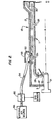
- the combustor of the invention comprises a burner defining an axial fluid-flow path between upstream and downstream ends thereof. As depicted in Figure 1, burner 1 defines an axial fluid flow path A between upstream end 3 and downstream end 5.
- burner 1 includes, in axial alignment, an upstream section defining a first combustion zone 7, a downstream section defining a second combustion zone 9, and an exhaust section 11 at the downstream end 5 of the burner.
- the combustor comprises a burner casing coaxially surrounding the burner and defining an annular conduit for inlet flow of combustion- supporting gas from downstream to upstream ends of the burner.
- burner casing 13 coaxially surrounds burner 1 and defines an annular conduit 15 for a flow of an inlet gas, generally compressed air, indicated by arrow 17 from downstream end 5 to upstream end 3 of burner 1.
- the inlet air is generally provided by a compressor 19 although it may be provided from any other source.
- the flow of inlet air 17 in annular chamber 15 provides convection cooling of burner 1 while preheating the inlet air.
- the combustor includes means for introducing fuel into the burner proximate the upstream end thereof.
- air blast fuel nozzle 20 projects through the upstream end 3 of burner 1 to inject fuel into first combustion zone 7.
- Other types of known fuel injectors may be used as generally depicted at 21 in Figure 2.
- the combustor includes at least a first means for introducing a primary part of the inlet gas into the burner proximate the upstream end thereof to generate a combustible fuel-air mixture.
- the upstream end 3 of burner 1 has openings 22 through which inlet air flows from annular chamber 15.
- Ports 22 disposed around air blast fuel nozzle 20 (Fig. 1) or 21 (Fig. 2) constitute primary means for introducing inlet air into first combustion zone 7 for mixing with the fuel injected through blast nozzle 20 or fuel injection nozzle 21.
- Burner 1 may also include apparatus (not shown) surrounding fuel nozzle 20 or 21 to induce swirling in the fuel-air mixture to enhance mixing.
- burner 1 incor- porates second means for introducing primary air into the burner at the intersection between first and second combustion zones 7, 9 for mixing with uncombusted fuel flowing from first combustion zone 7.
- a plurality of ports 24 are circumferentially disposed around the burner for communication with the downstream end of first combustion zone 7 and the upstream end of second combustion zone 9.
- the burner preferably includes means for introducing dilution air into the exhaust section 11 for controlling exhaust gas temperature.
- a plurality of ports 26 are spaced around the circumference of burner 1 for communication with exhaust section 11.
- Burner 1 may also include include ports 28 at the upstream end 3 thereof for introducing cooling gas or air about the inside periphery of first combustion zone 7.
- the cooling air can be made to generate swirling action within combustion zone 7 to enhance mixing within the combustion zone.
- ports 30 are provided at a junction between the first and second combustion zones 7 and 9 to introduce additional cooling air into second combustion zone 9 about the inside periphery of burner 1. This cooling air generates a swirling action within second combustion zone 9 to enhance the mixing of unburned fuel exiting from first combustion zone 7 with second primary air introduced through ports 24.
- inlet gas or air flows axially of the burner and is distributed among the various ports in certain proportions.
- 18% is the first primary air
- 18% is the second primary air
- 44% is dilution air
- 12% is first cooling air
- 8% is second cooling air.
- the combustor includes a restrictor means for introducing external gas into the annular conduit and for generating a pneumatic restriction to inlet gas flow to the primary means when the turbine is operating at predetermined operating conditions.
- the restrictor means comprises a plurality of slots 50 circumferentially spaced about burner casing 13, each slot directing external gas into the flow path of inlet gas 17 for generating annular vortex 52 restricting inlet gas flow through a portion 15a of the annular chamber 15.
- the annular vortex 52 is generated at a position downstream of the second primary inlet ports 24 and upstream of first primary inlet ports 22 and first cooling inlet ports 28.
- Annular vortex 52 constitutes a localized area of disturbed air in annular chamber 15 and forms a pneumatic restriction to the flow of inlet gas or air through that portion of annular chamber 15 thereby limiting the amount of inlet air introduced into first combustion chamber 7 through primary inlet ports 22.
- the restrictor means also includes a conduit 54 in communication with an external air source 56.
- the conduit may also include annular collector 58 in fluid communication with each slot 50; conduit 54 communicating external air to annular collector 58 in which the external air is distributed and directed through slots 50 into annular chamber 15.
- the restrictor means also includes valve 60 disposed to control fluid flow through conduit 54 and responsive to engine performance parameters.
- valve 60 is electrically activated by a signal from an engine operating condition sensor to open conduit 54 when the turbin* is operating at certain conditions, such as start and idle, and to close conduit 54 when the turbine is operating at other conditions, such as above idle.
- the operating condition is determined by sensing rotor speed, although any other parameter could be used which would indicate that the turbine is in the start or idle condition.
- the external air source 56 is the same source as provides external air for an air blast nozzle 20, and the valve 60 selectively opens and closes the conduit from external air source 56 in response to engine operating conditions to communicate external air to airblast valve 20 and to collectors 58.
- Conduit 54 connects with external air flow downstream of valve 60 and upstream of air blast nozzle 20.
- separate external air source 56 is provided and separate valve 62 responsive to an engine parameter sensor is placed in the conduit 54 connecting external air source 56 to collector 58.
- annular vortex 52 is only generated in annular chamber 15 when reduced fuel is being injected into first combustion zone 7 due to reduced power requirements.
- Generation of annular vortex 52 reduces the inlet air flow to primary inlet 22 thereby ensuring that optimum fuel air mixture is maintained in first combustion zone 7 through all ranges of power operation of the turbine.
Landscapes
- Engineering & Computer Science (AREA)
- Chemical & Material Sciences (AREA)
- Combustion & Propulsion (AREA)
- Mechanical Engineering (AREA)
- General Engineering & Computer Science (AREA)
- Physics & Mathematics (AREA)
- Fluid Mechanics (AREA)
- Separation By Low-Temperature Treatments (AREA)
- Pressure-Spray And Ultrasonic-Wave- Spray Burners (AREA)
Applications Claiming Priority (2)
| Application Number | Priority Date | Filing Date | Title |
|---|---|---|---|
| US610509 | 1984-05-15 | ||
| US06/610,509 US4628687A (en) | 1984-05-15 | 1984-05-15 | Gas turbine combustor with pneumatically controlled flow distribution |
Publications (1)
| Publication Number | Publication Date |
|---|---|
| EP0161561A1 true EP0161561A1 (fr) | 1985-11-21 |
Family
ID=24445307
Family Applications (1)
| Application Number | Title | Priority Date | Filing Date |
|---|---|---|---|
| EP85105055A Ceased EP0161561A1 (fr) | 1984-05-15 | 1985-04-25 | Chambre de combustion pour turbine à gaz avec circulation d'air réglable par action pneumatique |
Country Status (4)
| Country | Link |
|---|---|
| US (1) | US4628687A (fr) |
| EP (1) | EP0161561A1 (fr) |
| JP (1) | JPS6111525A (fr) |
| DE (1) | DE161561T1 (fr) |
Cited By (10)
| Publication number | Priority date | Publication date | Assignee | Title |
|---|---|---|---|---|
| WO1991004446A1 (fr) * | 1989-09-21 | 1991-04-04 | Allied-Signal Inc. | Procede et appareil de combustion d'une unite d'alimentation integree |
| WO1991004395A3 (fr) * | 1989-09-21 | 1992-03-05 | Allied Signal Inc | Unite d'alimentation integree |
| US5160069A (en) * | 1989-09-21 | 1992-11-03 | Allied-Signal Inc. | Integrated power unit combustion apparatus and method |
| US5161363A (en) * | 1989-09-21 | 1992-11-10 | Allied-Signal Inc. | Integrated power unit |
| EP0626543A1 (fr) * | 1993-05-24 | 1994-11-30 | Westinghouse Electric Corporation | Chambre de combustion à géométrie fixe avec basses émissions pour une turbine à gaz |
| EP0669500A1 (fr) * | 1994-02-18 | 1995-08-30 | ABB Management AG | Procédure pour le refroidissement d'une chambre de combustion à auto-ignition |
| EP0691512A3 (fr) * | 1994-07-05 | 1997-05-07 | Mowill Rolf Jan | Chambre de combustion annulaire à prémélange pour turbines à gaz |
| US5765363A (en) * | 1993-07-07 | 1998-06-16 | Mowill; R. Jan | Convectively cooled, single stage, fully premixed controllable fuel/air combustor with tangential admission |
| US5924276A (en) * | 1996-07-17 | 1999-07-20 | Mowill; R. Jan | Premixer with dilution air bypass valve assembly |
| US6220034B1 (en) | 1993-07-07 | 2001-04-24 | R. Jan Mowill | Convectively cooled, single stage, fully premixed controllable fuel/air combustor |
Families Citing this family (25)
| Publication number | Priority date | Publication date | Assignee | Title |
|---|---|---|---|---|
| US5163283A (en) * | 1990-07-31 | 1992-11-17 | Sundstrand Corporation | Stored energy system for driving a turbine wheel |
| KR930013441A (ko) * | 1991-12-18 | 1993-07-21 | 아더 엠.킹 | 다수의 연소기들을 포함한 가스터어빈 연소장치 |
| SE500150C2 (sv) * | 1992-08-28 | 1994-04-25 | Abb Carbon Ab | Sätt och anordning för att tillföra tillskottsluft till en brännkammare vid en gasturbinanläggning |
| US5680752A (en) * | 1992-08-28 | 1997-10-28 | Abb Carbon Ab | Gas turbine plant with additional compressor |
| USRE43252E1 (en) | 1992-10-27 | 2012-03-20 | Vast Power Portfolio, Llc | High efficiency low pollution hybrid Brayton cycle combustor |
| US5617719A (en) * | 1992-10-27 | 1997-04-08 | Ginter; J. Lyell | Vapor-air steam engine |
| AU7771494A (en) * | 1993-12-03 | 1995-06-08 | Westinghouse Electric Corporation | System for controlling combustion in a gas combustion-type turbine |
| US7047722B2 (en) * | 2002-10-02 | 2006-05-23 | Claudio Filippone | Small scale hybrid engine (SSHE) utilizing fossil fuels |
| US6826913B2 (en) | 2002-10-31 | 2004-12-07 | Honeywell International Inc. | Airflow modulation technique for low emissions combustors |
| US7007486B2 (en) * | 2003-03-26 | 2006-03-07 | The Boeing Company | Apparatus and method for selecting a flow mixture |
| US7117676B2 (en) * | 2003-03-26 | 2006-10-10 | United Technologies Corporation | Apparatus for mixing fluids |
| US7127899B2 (en) * | 2004-02-26 | 2006-10-31 | United Technologies Corporation | Non-swirl dry low NOx (DLN) combustor |
| US7707835B2 (en) * | 2005-06-15 | 2010-05-04 | General Electric Company | Axial flow sleeve for a turbine combustor and methods of introducing flow sleeve air |
| US7966822B2 (en) * | 2005-06-30 | 2011-06-28 | General Electric Company | Reverse-flow gas turbine combustion system |
| US7752850B2 (en) * | 2005-07-01 | 2010-07-13 | Siemens Energy, Inc. | Controlled pilot oxidizer for a gas turbine combustor |
| US7574870B2 (en) | 2006-07-20 | 2009-08-18 | Claudio Filippone | Air-conditioning systems and related methods |
| DE102006042124B4 (de) * | 2006-09-07 | 2010-04-22 | Man Turbo Ag | Gasturbinenbrennkammer |
| US8516822B2 (en) * | 2010-03-02 | 2013-08-27 | General Electric Company | Angled vanes in combustor flow sleeve |
| US9651138B2 (en) | 2011-09-30 | 2017-05-16 | Mtd Products Inc. | Speed control assembly for a self-propelled walk-behind lawn mower |
| US20130269359A1 (en) * | 2012-04-16 | 2013-10-17 | General Electric Company | Combustor flow sleeve with supplemental air supply |
| US20160010866A1 (en) * | 2013-02-19 | 2016-01-14 | United Technologies Corporation | Aerating fuel injector system for a gas turbine engine |
| US9228747B2 (en) * | 2013-03-12 | 2016-01-05 | Pratt & Whitney Canada Corp. | Combustor for gas turbine engine |
| RU2623592C1 (ru) * | 2016-06-16 | 2017-06-28 | Акционерное общество "Военно-промышленная корпорация "Научно-производственное объединение машиностроения" | Роторный газотурбинный двигатель |
| RU2702317C1 (ru) * | 2019-07-01 | 2019-10-07 | Сергей Константинович Исаев | Роторный биротативный газотурбинный двигатель |
| CN113803744B (zh) * | 2021-09-27 | 2023-03-10 | 中国联合重型燃气轮机技术有限公司 | 燃烧室入料装置及入料系统 |
Citations (8)
| Publication number | Priority date | Publication date | Assignee | Title |
|---|---|---|---|---|
| FR917080A (fr) * | 1944-11-30 | 1946-12-24 | Oerlikon Maschf | Chambre de combustion pour installations de turbines à gaz |
| FR1124095A (fr) * | 1954-03-01 | 1956-10-03 | Bristol Aeroplane Co Ltd | Perfectionnements aux moteurs à turbine à gaz |
| GB785210A (en) * | 1954-04-01 | 1957-10-23 | Power Jets Res & Dev Ltd | Combustion chambers |
| FR1463771A (fr) * | 1963-12-07 | 1966-07-22 | Snecma | Dispositif de réglage du débit de fluide dans un canal |
| US3910035A (en) * | 1973-05-24 | 1975-10-07 | Nasa | Controlled separation combustor |
| DE2416909A1 (de) * | 1974-04-06 | 1975-10-16 | Daimler Benz Ag | Betriebsverfahren fuer eine gasturbinenanlage zur abgasverbesserung und entsprechende gasturbinenanlage |
| FR2315664A1 (fr) * | 1975-06-25 | 1977-01-21 | Bbc Brown Boveri & Cie | Chambre de combustion |
| GB2024402A (en) * | 1978-06-29 | 1980-01-09 | Gen Electric | Combustion control system |
Family Cites Families (6)
| Publication number | Priority date | Publication date | Assignee | Title |
|---|---|---|---|---|
| US2807933A (en) * | 1954-04-01 | 1957-10-01 | Martin Peter | Combustion chambers |
| US2957306A (en) * | 1955-06-16 | 1960-10-25 | John S Attinello | Gas jets for controlling entrance and/or exit flow effective diameter |
| US3631675A (en) * | 1969-09-11 | 1972-01-04 | Gen Electric | Combustor primary air control |
| US3722218A (en) * | 1970-12-04 | 1973-03-27 | Parker Hannifin Corp | Air boost fuel atomizing system |
| US3738106A (en) * | 1971-10-26 | 1973-06-12 | Avco Corp | Variable geometry combustors |
| GB1581531A (en) * | 1976-09-09 | 1980-12-17 | Rolls Royce | Control of airflow in combustion chambers by variable rate diffuser |
-
1984
- 1984-05-15 US US06/610,509 patent/US4628687A/en not_active Expired - Fee Related
-
1985
- 1985-04-25 DE DE198585105055T patent/DE161561T1/de active Pending
- 1985-04-25 EP EP85105055A patent/EP0161561A1/fr not_active Ceased
- 1985-05-10 JP JP60098215A patent/JPS6111525A/ja active Pending
Patent Citations (8)
| Publication number | Priority date | Publication date | Assignee | Title |
|---|---|---|---|---|
| FR917080A (fr) * | 1944-11-30 | 1946-12-24 | Oerlikon Maschf | Chambre de combustion pour installations de turbines à gaz |
| FR1124095A (fr) * | 1954-03-01 | 1956-10-03 | Bristol Aeroplane Co Ltd | Perfectionnements aux moteurs à turbine à gaz |
| GB785210A (en) * | 1954-04-01 | 1957-10-23 | Power Jets Res & Dev Ltd | Combustion chambers |
| FR1463771A (fr) * | 1963-12-07 | 1966-07-22 | Snecma | Dispositif de réglage du débit de fluide dans un canal |
| US3910035A (en) * | 1973-05-24 | 1975-10-07 | Nasa | Controlled separation combustor |
| DE2416909A1 (de) * | 1974-04-06 | 1975-10-16 | Daimler Benz Ag | Betriebsverfahren fuer eine gasturbinenanlage zur abgasverbesserung und entsprechende gasturbinenanlage |
| FR2315664A1 (fr) * | 1975-06-25 | 1977-01-21 | Bbc Brown Boveri & Cie | Chambre de combustion |
| GB2024402A (en) * | 1978-06-29 | 1980-01-09 | Gen Electric | Combustion control system |
Cited By (12)
| Publication number | Priority date | Publication date | Assignee | Title |
|---|---|---|---|---|
| WO1991004446A1 (fr) * | 1989-09-21 | 1991-04-04 | Allied-Signal Inc. | Procede et appareil de combustion d'une unite d'alimentation integree |
| WO1991004395A3 (fr) * | 1989-09-21 | 1992-03-05 | Allied Signal Inc | Unite d'alimentation integree |
| US5160069A (en) * | 1989-09-21 | 1992-11-03 | Allied-Signal Inc. | Integrated power unit combustion apparatus and method |
| US5161363A (en) * | 1989-09-21 | 1992-11-10 | Allied-Signal Inc. | Integrated power unit |
| EP0626543A1 (fr) * | 1993-05-24 | 1994-11-30 | Westinghouse Electric Corporation | Chambre de combustion à géométrie fixe avec basses émissions pour une turbine à gaz |
| US5473881A (en) * | 1993-05-24 | 1995-12-12 | Westinghouse Electric Corporation | Low emission, fixed geometry gas turbine combustor |
| US5765363A (en) * | 1993-07-07 | 1998-06-16 | Mowill; R. Jan | Convectively cooled, single stage, fully premixed controllable fuel/air combustor with tangential admission |
| US6220034B1 (en) | 1993-07-07 | 2001-04-24 | R. Jan Mowill | Convectively cooled, single stage, fully premixed controllable fuel/air combustor |
| EP0669500A1 (fr) * | 1994-02-18 | 1995-08-30 | ABB Management AG | Procédure pour le refroidissement d'une chambre de combustion à auto-ignition |
| US5497611A (en) * | 1994-02-18 | 1996-03-12 | Abb Management Ab | Process for the cooling of an auto-ignition combustion chamber |
| EP0691512A3 (fr) * | 1994-07-05 | 1997-05-07 | Mowill Rolf Jan | Chambre de combustion annulaire à prémélange pour turbines à gaz |
| US5924276A (en) * | 1996-07-17 | 1999-07-20 | Mowill; R. Jan | Premixer with dilution air bypass valve assembly |
Also Published As
| Publication number | Publication date |
|---|---|
| DE161561T1 (de) | 1986-04-10 |
| US4628687A (en) | 1986-12-16 |
| JPS6111525A (ja) | 1986-01-18 |
Similar Documents
| Publication | Publication Date | Title |
|---|---|---|
| US4628687A (en) | Gas turbine combustor with pneumatically controlled flow distribution | |
| US4112676A (en) | Hybrid combustor with staged injection of pre-mixed fuel | |
| EP3076085B1 (fr) | Micromélangeur pour un système de turbine et son procédé associé | |
| EP0982545B1 (fr) | Chambre de combustion et procédé d'opération | |
| US5477671A (en) | Single stage premixed constant fuel/air ratio combustor | |
| US5640851A (en) | Gas turbine engine combustion chamber | |
| US5351474A (en) | Combustor external air staging device | |
| AU608083B2 (en) | Combustor for gas turbine | |
| US5475979A (en) | Gas turbine engine combustion chamber | |
| EP0600041B1 (fr) | Buse de combustion pour diminuer les emissions polluantes d'une turbine a gaz | |
| US5289685A (en) | Fuel supply system for a gas turbine engine | |
| EP0810405B1 (fr) | Méthode de fonctionnement d'une chambre de combustion pour une turbine à gaz | |
| US4463568A (en) | Fuel injector for gas turbine engines | |
| US4446692A (en) | Fluidic control of airflow in combustion chambers | |
| US6311496B1 (en) | Gas turbine fuel/air mixing arrangement with outer and inner radial inflow swirlers | |
| US5365738A (en) | Low emission combustion nozzle for use with a gas turbine engine | |
| US4651534A (en) | Gas turbine engine combustor | |
| US5309710A (en) | Gas turbine combustor having poppet valves for air distribution control | |
| US6880339B2 (en) | Combination of a premixing chamber and a combustion chamber, with low emission of pollutants, for gas turbines running on liquid and/or gas fuel | |
| US3541790A (en) | Hot gas generators | |
| KR20000057504A (ko) | 방사상으로 변위되는 고 운동량 연료출구를 갖춘 가스파일럿및그 방법 | |
| US6327860B1 (en) | Fuel injector for low emissions premixing gas turbine combustor | |
| US5285630A (en) | System for reducing nitrogen-oxide emissions from a gas turbine engine | |
| US4483138A (en) | Gas fuel injector for wide range of calorific values | |
| US5231822A (en) | High altitude turbine engine starting system |
Legal Events
| Date | Code | Title | Description |
|---|---|---|---|
| PUAI | Public reference made under article 153(3) epc to a published international application that has entered the european phase |
Free format text: ORIGINAL CODE: 0009012 |
|
| AK | Designated contracting states |
Designated state(s): DE FR GB SE |
|
| EL | Fr: translation of claims filed | ||
| DET | De: translation of patent claims | ||
| 17P | Request for examination filed |
Effective date: 19860512 |
|
| 17Q | First examination report despatched |
Effective date: 19870129 |
|
| STAA | Information on the status of an ep patent application or granted ep patent |
Free format text: STATUS: THE APPLICATION HAS BEEN REFUSED |
|
| 18R | Application refused |
Effective date: 19880409 |
|
| RIN1 | Information on inventor provided before grant (corrected) |
Inventor name: STROEM, SIGMUNN |