EP0161618B1 - Bobinoir - Google Patents
Bobinoir Download PDFInfo
- Publication number
- EP0161618B1 EP0161618B1 EP85105542A EP85105542A EP0161618B1 EP 0161618 B1 EP0161618 B1 EP 0161618B1 EP 85105542 A EP85105542 A EP 85105542A EP 85105542 A EP85105542 A EP 85105542A EP 0161618 B1 EP0161618 B1 EP 0161618B1
- Authority
- EP
- European Patent Office
- Prior art keywords
- winding
- contact
- contact roll
- fact
- winding machine
- Prior art date
- Legal status (The legal status is an assumption and is not a legal conclusion. Google has not performed a legal analysis and makes no representation as to the accuracy of the status listed.)
- Expired
Links
Images


Classifications
-
- B—PERFORMING OPERATIONS; TRANSPORTING
- B65—CONVEYING; PACKING; STORING; HANDLING THIN OR FILAMENTARY MATERIAL
- B65H—HANDLING THIN OR FILAMENTARY MATERIAL, e.g. SHEETS, WEBS, CABLES
- B65H67/00—Replacing or removing cores, receptacles, or completed packages at paying-out, winding, or depositing stations
- B65H67/04—Arrangements for removing completed take-up packages and or replacing by cores, formers, or empty receptacles at winding or depositing stations; Transferring material between adjacent full and empty take-up elements
- B65H67/044—Continuous winding apparatus for winding on two or more winding heads in succession
- B65H67/048—Continuous winding apparatus for winding on two or more winding heads in succession having winding heads arranged on rotary capstan head
-
- B—PERFORMING OPERATIONS; TRANSPORTING
- B65—CONVEYING; PACKING; STORING; HANDLING THIN OR FILAMENTARY MATERIAL
- B65H—HANDLING THIN OR FILAMENTARY MATERIAL, e.g. SHEETS, WEBS, CABLES
- B65H2701/00—Handled material; Storage means
- B65H2701/30—Handled filamentary material
- B65H2701/31—Textiles threads or artificial strands of filaments
Definitions
- the invention relates to a bobbin winder for continuously occurring threads for lossless bobbin change, as e.g. is shown in DE-C-23 64 284.
- a winding machine two chucks (referred to as winding spindles in the context of this application) are rotatably mounted and alternately in the winding operation.
- the winding spindles are mounted on a translating or rotating moving device.
- a so-called coil turret is used as the carrying device, which is rotatable about an axis and on which the two winding spindles are mounted opposite one another.
- DE-C-23 64 284 describes the problem of "starting" the winding spindle with the empty tubes when changing the bobbin. It is provided that - in the direction of rotation of the bobbin turret - a second contact roller connected to independent drive devices is arranged in front of the first contact roller, which takes over the drive of the winding spindle, so that in the phase of the bobbin change the bobbin spindle with the empty tubes through second contact roller started and the winding spindle with the full bobbins continues to be driven by the first contact roller.
- This solution has the disadvantage that the second contact roller, which in itself serves only as an "aid” for the short period of time when the empty tube is started, must have the high torque required for starting the winding spindle with high acceleration. This causes an unreasonable effort in view of the short-term stress.
- the second contact roller also serves as a traversing roller. This has turned out to be disadvantageous, since the functions of the traversing can only be reconciled with the function of applying the high starting torque for the empty spindle in a very short period of time with great technical effort.
- the object of the invention is to avoid these disadvantages.
- an auxiliary drive is to be created which has only a low torque to apply.
- the solution according to the invention which is expressed by the features set out in claim 1, on the one hand maintains that two contact rollers are provided.
- the contact roller which is only in operation temporarily, the winding spindle with the full bobbins clamped thereon is driven. No acceleration torque is required for this.
- the speed of the full bobbin drops slightly as a result of slippage or an insufficient torque, since the resulting thread entanglement has no adverse effects during the thread change that takes place in a matter of seconds.
- the first contact roller intended for continuous operation is also suitable without disadvantages to apply the torque required for starting the winding spindle with the empty tubes and to transmit it by means of frictional engagement with the empty tubes.
- An advantageous embodiment of this invention which is characterized by a very small amount of construction, small space and safe function, is characterized in that the first contact roller is driven by its drive motor via gear and that the second contact roller sits directly on the drive shaft of the drive motor, wherein the diameter of the first contact roller corresponds to the diameter of the second contact roller multiplied by the gear ratio of the transmission.
- the motor is preferably arranged parallel to and next to the first contact roller such that its first shaft end, on which the gear, in particular a toothed belt pulley is seated, lies in the same normal plane as the gear end of the first contact roller, while the other end of the drive shaft of the Motor ends approximately in the longitudinal center region of the first contact roller and the second contact roller seated on this end extends only over this longitudinal center region.
- the second contact roller arranged in the longitudinal center region of the first contact roller or winding spindles is arranged in such a way that it abuts the adjacent end regions of the coil.
- Both contact rollers and so-called measuring rollers are referred to as contact rollers in the context of this invention.
- the concept of this invention is particularly applicable in winding machines in which the winding spindles or coils are driven by means of the contact rollers.
- the contact rollers are equipped with drives which can apply the torque required to drive the coils.
- such friction rollers are in circumferential contact on the spool.
- the invention can also be applied to winding machines in which each winding spindle is driven by a motor (axle drive motor) acting directly on the coil.
- the contact rollers serve to measure the coil peripheral speeds and to control the speed of the final drive motors at such a speed that the coil peripheral speeds are adjusted to a substantially constant value will.
- the speed of the measuring roller is recorded.
- the measurement signal is then given to the control system, in particular the frequency converter of an axle drive motor.
- the final drive motor drives the spindle directly.
- a synchronous or asynchronous motor is preferably used as the final drive motor.
- the speed measurement is possible with greater accuracy in the phase of the bobbin change if - as furthermore preferably proposed - the contact rollers are constantly driven by an auxiliary drive motor with a power consumption which essentially corresponds to the idling power of the contact rollers.
- This drive is operated at a frequency such that the peripheral speed of the contact rollers at the nominal frequency is equal to the target peripheral speed of the coil.
- the current consumption or power or torque output of the one drive motor for the contact rollers is preferably used as the measurement signal for the surface speed of the measuring roller or coils.
- the constant drive of both contact rollers with only one drive motor makes it possible to change operation from one to the other winding spindle without switching over the measuring device and without significant changes in the measuring signal. There is therefore no danger that the measured variable leaves the control range and the drive motors of the Sputspindetn controlled by the measured variable fall out of step.
- the winding spindle with the empty tubes is only brought into a rotationally fixed connection with the first contact roller at a later point in time, since this winding spindle is driven with a special starter motor with a fixed predetermined starting frequency, which likewise gives the nominal peripheral speed of the winding spindle.
- a special starter motor with a fixed predetermined starting frequency, which likewise gives the nominal peripheral speed of the winding spindle.
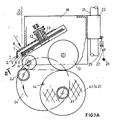
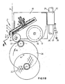
- each thread 3 is fed to the winding spindle 2. 1 or 2. 2 in the operating position and the empty tubes stretched thereon via traversing 1.
- the traversing for each thread consists of a two-, three- or four-armed wing star 7, which is driven in a first plane of rotation I by rotor 12, and an oppositely driven by star 13 wing star 8 with the same number of arms that in the Rotation level 11 rotates.
- Each thread 3 is fed back through the wings of one wing star 7 and through the arms of the other flight master 8 along a guide 9. 5 with a fender is designated, which has a longitudinal slot 6, which extends as a thread passage in front of each spool.
- the circumference of the winding spindles with the spools stretched thereon is driven by a first contact roller 11 in their operating position and by a second contact roller 10 in a transition position.
- the winding spindles are rotatably mounted on a turret 24, which is rotatable about the center 14 with the direction of rotation 15.
- the traversing mechanism 1 and the contact rollers 10 and 11 are mounted in a carriage 16 and can be moved up and down with the carriage.
- guides 21 are provided, on which bushes 22 slide.
- the contact roller 11 can avoid the growing coil diameter during operation without the turret 24 being rotated in the process.
- FIG. 2 corresponds to the coil change phase according to FIG. 1A.
- the winding spindle 2.1 rests on the contact roller 11 with the two empty tubes spanned thereon.
- the winding spindle 2.2 with the two spools 4.1 and 4.2 clamped thereon lies against the contact roller 10.
- the electric drive motor, a synchronous machine 17, is arranged on the carriage 16 axially parallel to the first contact roller 11, in such a way that one end of its drive shaft 18 with the toothed belt pulley 19 and one end of the contact roller 11 with the toothed belt pulley 20 on a common one Normal plane.
- the drive motor 17 and its drive shaft 18 extend over approximately half the length of the contact roller 11 and the winding spindle.
- the contact roller 10 is attached to the other end of the drive shaft 18.
- the contact roller 10 has a larger diameter than the housing of the motor 17 and, depending on the length of the motor 17, at least partially encompasses the housing.
- the contact roller 10 extends only over a partial length of the winding spindles, in such a way that it only engages the two coils 4.1 and 4.2 in their end regions.
- the contact roller 11 which is responsible for the exact thread placement on the bobbin according to the traversing law given by the traversing, has the smallest possible diameter.
- the contact roller 10 has a diameter that is larger than the housing of the drive motor 17.
- the diameter ratio D1 (contact roller 11) to D2 (contact roller 10) is equal to the transmission ratio, which is predetermined by the size of the toothed belt pulleys 19 and 20.
- the traversing device is not drawn in the schematic view of the winding machine according to FIG. 3.
- An essential part of the traversing is also the contact roller 11 shown in FIG. 3, which at the same time serves to guide the thread between the traversing and the bobbin and thus to shorten the drag length.
- FIG. 3 Also not shown in FIG. 3 is the frame of the winding machine and in particular a coil turret on which the winding spindles 2.1 and 2.2 are mounted. In this respect, too, reference is made to FIGS. 1A and 1B.
- Fig. 3 it is shown that the winding spindle 2.1 with the inserted empty tubes 30.1 and 30.2 has moved close to its operating position.
- the winding spindle 2.2 with the full bobbins 4.1 and 4.2 formed on the other hand is in the last phase of the winding operation, in which the folding of the threads 3.1 and 3.2 from the full bobbins 4.1.4.2 also the empty tubes 30.1, 30.2 are imminent.
- the winding spindle 2.2 is still driven by its final drive motor 28.
- the final drive motor 28 is a three-phase motor which is fed by the controllable frequency converter 31.
- the frequency converter 31 is controlled in such a way that the surface speed of the coils 4.1 and 4.2 remains constant despite the increasing coil diameter.
- the surface is scanned with the contact roller 10.
- the contact roller 10 extends only over a partial length, specifically over the adjacent end regions of the two coils 4.1 and 4.2.
- the contact roller 10 lies frictionally on the coil circumferences.
- the contact roller 10 is driven by the drive motor 17.
- the drive motor 17 is fed by frequency converter 33.
- the power consumed by the motor 17 is essentially equal to the idle power of the contact roller 10.
- the idle power is the power of the contact roller 10 that is required to drive the contact roller 10 at the required speed, but without contact with the coils 4.1, 4.2 to drive.
- This idle power also contains the power component that is required for the idle drive of the contact roller 11. It is essential that no torque is transmitted to the coils 4.1, 4.2 and the winding spindle 2.2 by the contact roller 10.
- a measuring device is designated.
- the current consumed by the drive motor 17 of the contact roller 10 or the power absorbed is measured.
- Suitable devices for measuring current or power are e.g. known from DE-C-25 35 457 and DE-C-26 06 093 (& US-A-4,069,985).
- Switch 34 connects measuring device 33 to frequency converter 31 in a closed control loop.
- This maximum speed is adjusted so that the peripheral speed of the empty tubes 30.1 and 30.2 essentially correspond to the peripheral speed of the coils 4.1 and 4.2 and the contact rollers 10 and 11. It is advantageous if the peripheral speed of the empty tubes is slightly higher, since this makes it easier to remove the threads from the full bobbins 4.1 and to apply the threads to the empty tubes 30.1 and 30.2. This change of the threads takes place in the drawn position of the winding spindles 2.1 and 2.2.
- Suitable devices for changing the threads between the full bobbins and the empty tubes are e.g. shown in US-A-3,913,852.
- the drives 28, 29 of the bobbin spindle can be adjusted to the required bobbin peripheral speed continuously and also in the phase of changing the thread.
Landscapes
- Replacing, Conveying, And Pick-Finding For Filamentary Materials (AREA)
Claims (11)
caractérisé par le fait que
le second rouleau de contact (10) est placé dans la trajectoire que les broches de bobinage (2.1,2.2) portant les bobines enroulées dessus suivent entre la position de fonctionnement et la position de changement de bobine.
caractérisé par le fait que
les deux rouleaux de contact (10, 11) sont constamment entraînés à une vitesse périphérique qui correspond sensiblement à la vitesse périphérique des bobines pour une vitesse prédéterminée du fil.
caractérisé par le fait que
les deux rouleaux de contact (10, 11) sont entraînés à même vitesse périphérique par un moteur unique (17).
caractérisé par le fait que
le premier rouleau de contact est entraîné par l'intermédiaire d'une transmission, par exemple une courroie dentée, par un moteur (17) parallèle à l'axe, que le second rouleau de contact (10) repose sur l'arbre du moteur (17) et que le rapport de multiplication 1 - vitesse de rotation du moteur (17)/vitesse de rotation du premier rouleau de contact (11) est égal au rapport des diamètres D2/D1 du second et du premier rouleaux de contact.
caractérisé par le fait que
le moteur (17) est placé parallèlement à l'axe et à côté du premier rouleau de contact (11) de façon qu'une extrémité de son arbre soit située dans le même plan normal qu'une extrémité du premier rouleau de contact (11) et que dans ce plan normal soit situé l'entraînement à courroie dentée, et qu'à l'autre extrémité de l'arbre est installé le second rouleau de contact (10) dont le diamètre est plus grand que le diamètre de la carcasse du moteur (17).
caractérisé par le fait que
le second rouleau de contact (10) est installé à peu près dans la zone médiane longitudinale du premier rouleau de contact (11).
caractérisé par le fait que
sur chaque broche de bobinage (2.1, 2.2) sont formées deux bobines et que le second rouleau de contact (10) s'étend sur les zones d'extrémités, mutuellement voisines, des deux bobines.
caractérisé par le fait que
les broches de bobinage (2.1, 2.2) sont montées en rotation libre et qu'il est prevu un moteur de démarrage qui est raccordé à la broche de bobinage portant les tubes vides et entraîne cette dernière avant que les tubes vides ne soient appliqués sur la périphérie du premier rouleau de contact (11).
caractérisé par le fait que
chacune des broches de bobinage est respectivement entraînée par un moteur à courant triphasé avec convertisseur de fréquence et que le convertisseur de fréquence, qui alimente le moteur à courant triphasé de la broche portant les bobines pleines, est commandé en fonction du courant ou de la puissance absorbée du second rouleau de contact.
caractérisé par le fait que
les broches de bobinage sont montées mobiles en rotation sur un dispositif-révolver (24) rotatif ou pivotable.
caractérisé par
un dispositif de va-et-vient à pales.
Applications Claiming Priority (6)
| Application Number | Priority Date | Filing Date | Title |
|---|---|---|---|
| DE19843417693 DE3417693A1 (de) | 1984-05-12 | 1984-05-12 | Spulmaschine |
| DE3417693 | 1984-05-12 | ||
| DE3430489 | 1984-08-18 | ||
| DE3430489 | 1984-08-18 | ||
| DE3510903 | 1985-03-26 | ||
| DE3510903 | 1985-03-26 |
Publications (2)
| Publication Number | Publication Date |
|---|---|
| EP0161618A1 EP0161618A1 (fr) | 1985-11-21 |
| EP0161618B1 true EP0161618B1 (fr) | 1987-03-18 |
Family
ID=27191966
Family Applications (1)
| Application Number | Title | Priority Date | Filing Date |
|---|---|---|---|
| EP85105542A Expired EP0161618B1 (fr) | 1984-05-12 | 1985-05-07 | Bobinoir |
Country Status (4)
| Country | Link |
|---|---|
| US (1) | US4602747A (fr) |
| EP (1) | EP0161618B1 (fr) |
| JP (1) | JPS6123091A (fr) |
| DE (1) | DE3560089D1 (fr) |
Cited By (1)
| Publication number | Priority date | Publication date | Assignee | Title |
|---|---|---|---|---|
| DE3744209A1 (de) * | 1987-12-24 | 1989-07-06 | Rieter Ag Maschf | Verfahren zum fangen eines synthetischen garnes waehrend des spulenwechsels bei einem aufspulautomaten sowie vorrichtung zur durchfuehrung des verfahrens |
Families Citing this family (9)
| Publication number | Priority date | Publication date | Assignee | Title |
|---|---|---|---|---|
| ES2050766T3 (es) * | 1988-12-22 | 1994-06-01 | Barmag Barmer Maschf | Maquina bobinadora. |
| DE19802509A1 (de) * | 1998-01-23 | 1999-07-29 | Rieter Ag Maschf | Aufwindevorrichtung für Endlosfäden |
| DE29908962U1 (de) * | 1999-05-21 | 1999-09-02 | Neumag - Neumünstersche Maschinen- und Anlagenbau GmbH, 24536 Neumünster | Aufspulmaschine |
| DE102005050074A1 (de) * | 2005-10-19 | 2007-04-26 | Saurer Gmbh & Co. Kg | Auflaufeinrichtung für Arbeitsstellen von Doppeldraht-Zwirn- und Kabliermaschinen |
| CN103407840B (zh) * | 2013-08-29 | 2016-01-06 | 无锡宏源机电科技股份有限公司 | 一种弹力丝机的控制系统及其控制方法 |
| US10538379B2 (en) | 2014-03-11 | 2020-01-21 | Lincoln Global, Inc. | Welding wire coil package |
| USD761637S1 (en) | 2014-05-07 | 2016-07-19 | Lincoln Global, Inc. | Wire coil package |
| US9950895B2 (en) | 2014-07-03 | 2018-04-24 | Lincoln Global, Inc. | Welding wire coil packaging system |
| CN116424945B (zh) * | 2023-04-18 | 2023-10-31 | 江苏天明机械集团有限公司 | 一种主动卷绕机及其卷绕方法 |
Family Cites Families (17)
| Publication number | Priority date | Publication date | Assignee | Title |
|---|---|---|---|---|
| CH418917A (de) * | 1963-08-01 | 1966-08-15 | Inst Textilmaschinen | Vorrichtung für Spinn- und Spulmaschinen zum ununterbrochenen Aufwinden eines Fadens |
| US3279709A (en) * | 1963-11-18 | 1966-10-18 | Gustin Bacon Mfg Co | Textile fiber winder |
| GB1104156A (en) * | 1965-03-04 | 1968-02-21 | Ici Fibres Ltd | Improvements in or relating to the collection of filaments or yarns |
| GB1275561A (en) * | 1968-05-03 | 1972-05-24 | Fairbairn Lawson Ltd | Improvements in or relating to textile thread winding apparatus |
| JPS5134017B1 (fr) * | 1969-09-05 | 1976-09-24 | ||
| US3856222A (en) * | 1969-10-03 | 1974-12-24 | Rieter Ag Maschf | Method of automatically changing winding tubes and winding apparatus for implementing the aforesaid method and improved spool doffing mechanism |
| DE2043246A1 (de) * | 1970-09-01 | 1972-03-16 | Barmag Barmer Maschinenfabrik Ag, 5600 Wuppertal | Spulvorrichtung für synthetische Fäden |
| CH523843A (de) * | 1971-03-04 | 1972-06-15 | Barmag Barmer Maschf | Spulvorrichtung mit Treibwalzenantrieb zum Aufwickeln endloser Fäden |
| US3913852A (en) * | 1973-03-31 | 1975-10-21 | Barmag Barmer Maschf | Winding apparatus and process |
| CH572435A5 (fr) * | 1973-12-22 | 1976-02-13 | Barmag Barmer Maschf | |
| DE2364284C2 (de) * | 1973-12-22 | 1975-11-20 | Barmag Barmer Maschinenfabrik Ag, 5600 Wuppertal | Spulmaschine |
| CH618401A5 (fr) * | 1975-06-12 | 1980-07-31 | Barmag Barmer Maschf | |
| DE2655544C2 (de) * | 1976-12-08 | 1978-07-20 | Barmag Barmer Maschinenfabrik Ag, 5630 Remscheid | Spulvorrichtung mit Umfangsantrieb zum Aufspulen von Chemiefasern |
| JPS5878953A (ja) * | 1981-11-04 | 1983-05-12 | Teijin Ltd | 糸条巻取装置 |
| US4505436A (en) * | 1983-01-19 | 1985-03-19 | Barmag Barmer Maschinenfabrik Ag | Yarn winding apparatus |
| EP0114641B1 (fr) * | 1983-01-19 | 1986-05-28 | b a r m a g Barmer Maschinenfabrik Aktiengesellschaft | Machine à bobiner avec guide-fil à pales |
| US4505437A (en) * | 1983-01-29 | 1985-03-19 | Barmag Barmer Maschinenfabrik Ag | Apparatus for winding a plurality of yarns |
-
1985
- 1985-05-07 EP EP85105542A patent/EP0161618B1/fr not_active Expired
- 1985-05-07 DE DE8585105542T patent/DE3560089D1/de not_active Expired
- 1985-05-13 JP JP60099747A patent/JPS6123091A/ja active Pending
- 1985-05-13 US US06/733,596 patent/US4602747A/en not_active Expired - Fee Related
Cited By (1)
| Publication number | Priority date | Publication date | Assignee | Title |
|---|---|---|---|---|
| DE3744209A1 (de) * | 1987-12-24 | 1989-07-06 | Rieter Ag Maschf | Verfahren zum fangen eines synthetischen garnes waehrend des spulenwechsels bei einem aufspulautomaten sowie vorrichtung zur durchfuehrung des verfahrens |
Also Published As
| Publication number | Publication date |
|---|---|
| DE3560089D1 (en) | 1987-04-23 |
| JPS6123091A (ja) | 1986-01-31 |
| US4602747A (en) | 1986-07-29 |
| EP0161618A1 (fr) | 1985-11-21 |
Similar Documents
| Publication | Publication Date | Title |
|---|---|---|
| EP0374536B1 (fr) | Machine de bobinage | |
| EP0921087B1 (fr) | Procédé et dispositif de bobinage pour bobiner un fil textile alimenté en continu | |
| EP0200234B1 (fr) | Commande de broche de bobinage | |
| EP0165428A2 (fr) | Machine textile avec plusieurs unités de bobinage de fil à vitesse constante sur bobine conique | |
| DE2661121C2 (fr) | ||
| DE10223484A1 (de) | Verfahren und Spulmaschine zum Aufwickeln eines kontinuierlich zulaufenden Fadens auf eine Hülse zu einer Spule | |
| EP0161618A1 (fr) | Bobinoir | |
| CH693380A5 (de) | Verfahren und Vorrichtung zum Aufspulen eines kontinuierlich zulaufenden Fadens. | |
| DE2125552C3 (de) | Vorrichtung zum Wickeln von elektrischen Spulen | |
| EP1747160B1 (fr) | Procede et dispositif permettant l'enroulement en continu de plusieurs fils | |
| DE3513796C2 (fr) | ||
| DE2364284C2 (de) | Spulmaschine | |
| DE2623175A1 (de) | Garnwickelvorrichtung | |
| DE3324243A1 (de) | Falschzwirnkraeuselmaschine und verfahren zur ueberbrueckung kurzzeitiger spannun gsausfaelle an textilmaschinen | |
| EP0166292A1 (fr) | Va et vient pour bobinoir | |
| DE2406641A1 (de) | Aufwickelvorrichtung mit automatischem wechsel von huelsen | |
| DE2345720A1 (de) | Verfahren und vorrichtung zum herstellen von litze | |
| DE3211603C2 (de) | Verfahren zum verlustfreien Spulenwechsel beim Aufspulen eines kontinuierlich zulaufenden Fadens sowie Aufspulvorrichtung | |
| DE3040974C2 (fr) | ||
| DE4115339A1 (de) | Spulhuelse | |
| DE19628402A1 (de) | Verfahren zur Vermeidung von Bildwicklungen | |
| DE3909106A1 (de) | Aufspulmaschine | |
| DE3113143C2 (de) | Wickelmaschine für orthozyklisches Spulen | |
| DE2350399C2 (de) | Wickelmaschine zur Herstellung von Wendelglühkörpern für elektrische Lampen | |
| DE3915608A1 (de) | Aufspulmaschine |
Legal Events
| Date | Code | Title | Description |
|---|---|---|---|
| PUAI | Public reference made under article 153(3) epc to a published international application that has entered the european phase |
Free format text: ORIGINAL CODE: 0009012 |
|
| AK | Designated contracting states |
Designated state(s): CH DE FR GB IT LI |
|
| 17P | Request for examination filed |
Effective date: 19851028 |
|
| 17Q | First examination report despatched |
Effective date: 19860514 |
|
| ITF | It: translation for a ep patent filed | ||
| RAP1 | Party data changed (applicant data changed or rights of an application transferred) |
Owner name: B A R M A G AG |
|
| GRAA | (expected) grant |
Free format text: ORIGINAL CODE: 0009210 |
|
| AK | Designated contracting states |
Kind code of ref document: B1 Designated state(s): CH DE FR GB IT LI |
|
| REF | Corresponds to: |
Ref document number: 3560089 Country of ref document: DE Date of ref document: 19870423 |
|
| ET | Fr: translation filed | ||
| PLBE | No opposition filed within time limit |
Free format text: ORIGINAL CODE: 0009261 |
|
| STAA | Information on the status of an ep patent application or granted ep patent |
Free format text: STATUS: NO OPPOSITION FILED WITHIN TIME LIMIT |
|
| 26N | No opposition filed | ||
| PGFP | Annual fee paid to national office [announced via postgrant information from national office to epo] |
Ref country code: GB Payment date: 19900427 Year of fee payment: 6 |
|
| PG25 | Lapsed in a contracting state [announced via postgrant information from national office to epo] |
Ref country code: GB Effective date: 19910507 |
|
| PGFP | Annual fee paid to national office [announced via postgrant information from national office to epo] |
Ref country code: CH Payment date: 19910527 Year of fee payment: 7 |
|
| PGFP | Annual fee paid to national office [announced via postgrant information from national office to epo] |
Ref country code: DE Payment date: 19910529 Year of fee payment: 7 |
|
| PGFP | Annual fee paid to national office [announced via postgrant information from national office to epo] |
Ref country code: FR Payment date: 19910530 Year of fee payment: 7 |
|
| ITTA | It: last paid annual fee | ||
| GBPC | Gb: european patent ceased through non-payment of renewal fee | ||
| PG25 | Lapsed in a contracting state [announced via postgrant information from national office to epo] |
Ref country code: LI Effective date: 19920531 Ref country code: CH Effective date: 19920531 |
|
| PG25 | Lapsed in a contracting state [announced via postgrant information from national office to epo] |
Ref country code: FR Effective date: 19930129 |
|
| REG | Reference to a national code |
Ref country code: CH Ref legal event code: PL |
|
| PG25 | Lapsed in a contracting state [announced via postgrant information from national office to epo] |
Ref country code: DE Effective date: 19930202 |
|
| REG | Reference to a national code |
Ref country code: FR Ref legal event code: ST |