EP0161726A2 - Presse à balles rondes - Google Patents
Presse à balles rondes Download PDFInfo
- Publication number
- EP0161726A2 EP0161726A2 EP85200748A EP85200748A EP0161726A2 EP 0161726 A2 EP0161726 A2 EP 0161726A2 EP 85200748 A EP85200748 A EP 85200748A EP 85200748 A EP85200748 A EP 85200748A EP 0161726 A2 EP0161726 A2 EP 0161726A2
- Authority
- EP
- European Patent Office
- Prior art keywords
- bale
- bale forming
- forming means
- round baler
- chamber
- Prior art date
- Legal status (The legal status is an assumption and is not a legal conclusion. Google has not performed a legal analysis and makes no representation as to the accuracy of the status listed.)
- Granted
Links
- 230000015572 biosynthetic process Effects 0.000 claims description 18
- 239000000463 material Substances 0.000 claims description 8
- 239000012530 fluid Substances 0.000 claims description 2
- 230000001419 dependent effect Effects 0.000 claims 4
- 230000004048 modification Effects 0.000 description 3
- 238000012986 modification Methods 0.000 description 3
- 238000004519 manufacturing process Methods 0.000 description 2
- 238000010276 construction Methods 0.000 description 1
- 230000003247 decreasing effect Effects 0.000 description 1
- 238000007599 discharging Methods 0.000 description 1
- 239000002184 metal Substances 0.000 description 1
Images



Classifications
-
- A—HUMAN NECESSITIES
- A01—AGRICULTURE; FORESTRY; ANIMAL HUSBANDRY; HUNTING; TRAPPING; FISHING
- A01F—PROCESSING OF HARVESTED PRODUCE; HAY OR STRAW PRESSES; DEVICES FOR STORING AGRICULTURAL OR HORTICULTURAL PRODUCE
- A01F15/00—Baling presses for straw, hay or the like
- A01F15/07—Rotobalers, i.e. machines for forming cylindrical bales by winding and pressing
-
- A—HUMAN NECESSITIES
- A01—AGRICULTURE; FORESTRY; ANIMAL HUSBANDRY; HUNTING; TRAPPING; FISHING
- A01F—PROCESSING OF HARVESTED PRODUCE; HAY OR STRAW PRESSES; DEVICES FOR STORING AGRICULTURAL OR HORTICULTURAL PRODUCE
- A01F15/00—Baling presses for straw, hay or the like
- A01F15/07—Rotobalers, i.e. machines for forming cylindrical bales by winding and pressing
- A01F2015/079—Sledge for rollers of the pressing chamber
-
- A—HUMAN NECESSITIES
- A01—AGRICULTURE; FORESTRY; ANIMAL HUSBANDRY; HUNTING; TRAPPING; FISHING
- A01F—PROCESSING OF HARVESTED PRODUCE; HAY OR STRAW PRESSES; DEVICES FOR STORING AGRICULTURAL OR HORTICULTURAL PRODUCE
- A01F15/00—Baling presses for straw, hay or the like
- A01F15/07—Rotobalers, i.e. machines for forming cylindrical bales by winding and pressing
- A01F2015/0795—Pressing chamber with variable volume
Definitions
- This invention relates generally to roll baling machines, typically referred to as round balers which form cylindrical roll bales of crop material.
- U.S. Patent No. 4,198,804 discloses a conventional type of round baler having a two part frame with rollers extending transversely between the side walls of the frame.
- the rollers are stationarily mounted on the frame to define a generally cylindrical baling zone which has a fixed diameter.
- the two parts of the baler frame are pivotally connected so that the baling zone may be opened to discharge a bale therefrom.
- a disadvantage of this type of baler is that it is often difficult and sometimes impossible to form bales when working in short brittle crop material.
- Another disadvantage is that the bales produced with this type of baler have a soft core and often have a low density.
- baler typically has an expandable baling zone.
- the baling zone When bale formation is started, the baling zone has reduced dimensions defining a bale starting chamber for facilitating the start of the bale formation or the so-called core-forming.
- the bale chamber gradually expands as the bale being formed in the bale chamber grows. Ultimately the bale chamber reaches its maximum diameter cylindrical shape when the bale being formed reaches completion.
- baler usually is more complicated in design and more expensive in manufacture.
- baler has the advantage of being able to produce bales of a more uniform and higher density.
- bales formed.with a baler according to the present invention may have the nice and smooth finish which is typical for bales formed with fixed chamber round balers.
- a round baler with a bale forming chamber expandable between a bale starting position and a full bale position comprises a first set of bale forming means disposed at fixed positions generally circumferentially around a portion of the full size bale chamber when the baler is in its bale forming condition, i.e. when the rear movable frame or so-called tailgate is in its lowered position.
- the baler according to the present invention is characterized in that arm means are pivotally mounted on the baler; the arm means carrying a second set of bale forming means.
- the first and second sets of bale forming means cooperate to form a round bale of crop material.
- the arm means during bale formation, are movable between :
- the bale forming means of the first and second sets of bale forming means are formed by a plurality of transversely extending rollers; the rollers of the first set being rotatably mounted at fixed positions on the baler and the rollers of the second set being rotatably mounted on the arm means for pivotal movement iiu unison therewith.
- the arm means comprise a pair of arms, each pivoted at one end on the baler, and transverse beams interconnecting the arms at spaced apart locations along the length thereof to form a rigid frame of generally rectangular shape as seen in a direction perpendicular to its main dimensions.
- the arms are generally arcuate in shape when seen in side view, to define in part, the generally cylindrical shape of the bale chamber when positioned in its full bale position.
- the second set of bale forming means extends transversely between the opposed arms; the rollers thereof being rotatably mounted on said arms.
- the round baler according to the present invention also comprises a base frame and a movable subframe pivotally connected thereto for movement between a bale forming position and a bale discharge position.
- the arm means with the second set of bale forming means thereon are pivotally mounted on the base frame. At least some of the bale forming means of the first set of bale forming means are mounted at fixed positions on the movable subframe.
- the arm means are movable between :
- the arm means with the second set of bale forming means thereon are pivotally mounted on the movable subframe and at least some of the bale forming means of the first set of bale forming means are mounted at fixed positions on the base frame.
- the arm means are movable between :
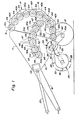
- a round baler according to one embodiment of the present invention includes a base frame 10 supported by a pair of wheels 12 and a rear movable subframe 14 pivotally connected to the base frame 10 by stub shafts 16 mounted in suitable bearings.
- the side walls 11 of the base frame 10 are generally triangular in shape, and the side walls 15 of the rear frame 14 are generally trapezoidal in shape.
- a tongue 18 is provided on the forward end of the base frame 10 for connection to a towing vehicle such as a tractor (not shown).
- a drive shaft 20 is adapted for connection at one end to the PTO of the tractor and at the other end to a gearbox 22 carried on the base frame 10.
- a pickup 24 extends transversely of the base frame 10 and is supported by brackets 26 which are attached to the side walls 11 of the base frame 10.
- the pickup 24 includes a series of fingers or tines 28 movable in a path designated 30.
- a feeder drum 32 is rotatably mounted on the base frame 10 and extends transversely between the sidewalls 11 thereof.
- the feeder drum 32 includes a cylinder 33 and a plurality of fingers 34 mounted on a shaft 36 that is eccentrically offset with respect to the shaft 35 on which the cylinder 33 is mounted. As the cylinder 33 is rotated by the shaft 35, the fingers 34 retract into and project from openings in the cylinder 33. The tips of the fingers 34 follow a path designated 38.
- a set of rollers 40a through 40j is rotatably mounted at fixed positions in the rear frame 14 and extend transversely between the side walls 15 of the rear frame 14.
- Spur gears 42 are fixed to one end of each of the rollers 40a to 40j outside the adjacent side wall 15, and intermediate gears 44 are rotatably mounted on the outside of the same side wall 15 of the rear frame 14 in intermeshing engagement with the spur gears 42.
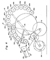
- a pair of arms 46 are pivoted at one end on stub shafts 48 mounted in the side walls 11 of the base frame 10 for movement between a bale starting position shown in Fig. 1 and a full bale position shown in Fig. 2.
- the arms 46 are interconnected by beams 47 which extend transversely of the base frame 10.
- the arms 46 together with the beams 47 form a rigid frame of generally rectangular shape when seen in a direction perpendicular to the main dimensions of said frame. When viewed in side view, the arms 46 have a generally arcuate shape to correspond to the cylindrical full size bale chamber when the arms 46 are in the full bale position.
- Another set of rollers 50a through 50f is rotatably carried on the arms 46 and extends transversely between the arms 46.
- Spur gears 52 are fixed to one end of each of the rollers 50a through 50f on the inside of the adjacent arm 46, and intermediate gears 54 are rotatably carried on the inside of the same arm 46 in intermeshing engagement with the spur gears 52.
- the rollers 40a through 40j and the rollers 50a through 50f each consist preferably of a hollow drumlike member formed of sheet metal mounted on a shaft which extends longitudinally of the drumlike member. The ends of the shaft project from the drumlike member and are rotatably mounted in suitable bearings disposed in either the sidewalls 15 of the rear frame 14 or in the arms 46.
- the shaft of the roller 40j is coaxial with and fixed to the stub shafts 16, and the shaft of the roller 50a is coaxial with and fixed to the stub shafts 48.
- a sprocket 56 is fixed to the output shaft of the gearbox 22, and a chain 58 connects the sprocket 56 to a triple sprocket arrangement 60 which is fixed to one of the stub shafts 48 to drive the roller 50a.
- a chain 62 connects the triple sprocket arrangement 60 to a sprocket 64 fixed to one of the stub shafts 16 to drive the roller 40j.
- Another chain 66 connects the triple sprocket arrangement 60 to a sheave and sprocket combination 68 that is fixed to the shaft 35 of the feeder drum 32.
- a belt 70 connects the sheave and sprocket combination 68 to a sheave 72 on the pickup 24.
- Idlers 74 are provided to maintain proper tension in the chain 62 and in the belt 70.
- a pair of hydraulic cylinders 76 are connected between the side walls 11 of the base frame 10 and the side walls 15 of the rear frame 14.
- Another pair of hydraulic cylinders 78 are connected between lever portions 80 of the arms 46 and the side walls 11 of the base frame 10.
- the hydraulic cylinders 78 may be replaced by a pair of springs 82 connected between the lever portions 80 of the arms 46 and the side walls 11 of the base frame 10.
- Rotary driving power is delivered from the PTO of the tractor through the drive shaft 20 and the gearbox 22 to rotate the sprocket 56 in a clockwise direction as indicated in Fig. 2.
- This rotation of the sprocket 56 causes the triple sprocket arrangement 60 to be rotated clockwise by the chain 58, resulting in concurrent clockwise rotation of the roller 50a.
- Due to the spur gears 52 and the intermediate gears 54 the other rollers 50b through 50f carried on the arms 46 are also rotated clockwise.
- the roller 40j mounted in the rear frame 14 is rotated clockwise by the chain 62 and the sprocket 64. Due to the spur gears 42 and the intermediate gears 44, the remaining rollers 40a through 40i mounted in the rear frame 14 are also rotated clockwise.
- the feeder drum 32 is also caused to rotate in a clockwise direction by the chain 66 which, in turn, causes the fingers 34 to move along the path 38.
- the fingers 28 of the pickup 24 are caused to rotate in the path 30 by the belt 70.
- the arms 46 When the baler is empty as seen in Fig. 1, the arms 46 are in their bale starting position and the rollers 50a through 50j cooperate with the feeder drum 32 and with the rollers 40a through 40d in the rear movable subframe 14 to define a bale starting chamber 84 which is elongated in a generally horizontal direction.
- the roller 50a is spaced from the feeder drum 32 a sufficient distance to provide an inlet 85 to the bale starting chamber 84.
- the pickup fingers 28 and the fingers 34 of the feeder drum 32 deliver crop material into the bale starting chamber 84 through the inlet 85 to form the core of a roll bale.
- the arms 46 As the bale increases in diameter, the arms 46 are pivoted upwardly toward the full bale position of Fig.
- said cylinders are part of a hydraulic circuitry also comprising a pressure relief valve which is operable, during bale formation, to allow pressure fluid to drain from the cylinders 78 upon the bale, during its formation, exerting a predetermined back pressure on the arms 46.
- the pressure relief valve preferably is adjustable to allow the operator to vary the density of the bales being formed.
- the hydraulic cylinders 76 When a full bale 86 has been formed as shown in Fig. 2, and it is desired to discharge the bale, the hydraulic cylinders 76 are extended thereby pivoting the rear frame 14 upwardly as shown in Fig. 3.
- the hydraulic cylinders 78 may hold the arms 46 and the rollers 50a through 50f in the full bale position during discharge of the bale.
- the springs 82 are used as shown in Fig. 4
- the arms 46 and the rollers 50a through 50f are urged by the springs 82 toward the bale starting position to assist in discharging the bale.
- the hydraulic cylinders 76 After the bale is discharged, the hydraulic cylinders 76 are contracted to move the rear frame or so-called tailgate 14 back to the position of Fig. 1 and the arms 46 are returned to the bale starting position so that the baler is ready to form another bale.
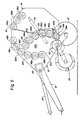
- a round baler according to another embodiment of the present invention includes a set of rollers 88a through 88f rotatably mounted at fixed positions in the base frame 10 and extending transversely between the side walls 11 thereof.
- Another set of rollers 90a through 90c is rotatably mounted at fixed positions in the rear frame or tailgate 14 and extends transversely between the side walls 15 thereof.
- a pair of arms 92 which are similar to the arms 46 previously described, are pivoted at one end on stub shafts 94 mounted in the side walls 15 of the rear movable subframe 14. The arms 92 are interconnected by beams 93.
- a further set of rollers 96a through 96f is rotatably carried by the arms 92 and extends transversely between the arms 92.
- a pair of hydraulic cylinders 98 is connected between lever portions 100 of the arms 92 and the side walls 15 of the rear frame 14.
- the rollers 88a through 88f, 90a through 90c, and 96a through 96f are essentially of the same construction as the rollers 40a through 40j and 50a through 50f previously described.
- the shaft of the roller 90a is coaxial with and fixed to the stub shafts 16, and the shaft of the roller 96a is coaxial with and fixed to the stub shafts 94.
- the rollers of each set shown in the embodiment of Fig. 5 are interconnected by the same type of arrangement of spur gears and intermediate gears already described.
- rollers 88a through 88f, 90a through 90c and 96a through 96f are each rotated in a clockwise direction as viewed in Fig. 5.
- the arms 92 are in a bale starting position so that the rollers 96a through 96f carried thereon cooperate with the feeder drum 32 and with the rollers 88a through 88c to define a bale starting chamber 102 which is elongated in a generally vertical direction.
- the roller 88a is spaced from the feeder drum 32 a sufficient distance to provide an inlet 103 to the bale starting chamber 102.
- the pickup 24 and the feeder drum 32 deliver crop material into the bale starting chamber 102 through the inlet 103 to form the core of a roll bale.
- the arms 92 are moved toward a full bale position against the force of the hydraulic cylinders 98.
- the hydraulic cylinders 76 When a full bale has been formed and it is desired to discharge the bale, the hydraulic cylinders 76 are extended, thereby pivoting the movable subframe 14 upwardly as shown in Fig. 6.
- the hydraulic cylinders 98 hold the arms 92 and the rollers 96a through 96f in the full bale position during discharge of the bale 104.
- the hydraulic cylinders 76 After the bale 104 is discharged, the hydraulic cylinders 76 are contracted to move the subframe 14 back to the position of Fig. 5 and the arms 92 are returned to the bale starting position so that the baler is ready to form another bale.
- rollers in each set may be increased or decreased if desired.
- the roller 90c will be added to the set of rollers 96a to 96f carried on the arms 92.
- the term "rollers" as used herein should not be limited to the particular type and shape of rollers 40a to 40j, 50a to 50f, 88a to 88f, 90a to 90c, and 96a to 96f disclosed herein.
- the rollers may have a different shape.
- the rollers may be replaced by other bale forming members.
- first and second arm means may be pivotally mounted on the baler.
- Each arm means carries its own set of bale forming means/in side-by-side relationship.
- Said bale forming means again preferably are in the form of rollers.
- the sets of bale forming means on the pivotally mounted first and second arm means cooperate with a further set of bale forming means mounted at fixed positions on the baler to form a roll bale of crop material.
- the first and second arm means are movable during bale formation between :
- the first and second arm means are comparable in shape and dimensions with the pivotally mounted arm means 46, respectively 92 shown in Figures 1-4 respectively Figures 5-6.
- the first arm means may be pivotally mounted on the base frame 10 via the stub shafts 48 shown in Figures 1-4, while that the second arm means may be pivotally mounted on the movable subframe 14 via the stub shafts 94 shown in Figures 5-6.
- the arrangement is such that, when moved to the bale starting position, the first and second arm means are pivoted toward each other around their lower pivotal mountings to form a generally upright elongated bale starting chamber having, at the lower end thereof and adjacent the respective pivotal mountings, the feeder drum 32.
Landscapes
- Life Sciences & Earth Sciences (AREA)
- Environmental Sciences (AREA)
- Storage Of Harvested Produce (AREA)
Applications Claiming Priority (4)
| Application Number | Priority Date | Filing Date | Title |
|---|---|---|---|
| US61210084A | 1984-05-18 | 1984-05-18 | |
| US612101 | 1984-05-18 | ||
| US612100 | 1984-05-18 | ||
| US06/612,101 US4566379A (en) | 1984-05-18 | 1984-05-18 | Round baler with vertically elongated starting chamber |
Publications (3)
| Publication Number | Publication Date |
|---|---|
| EP0161726A2 true EP0161726A2 (fr) | 1985-11-21 |
| EP0161726A3 EP0161726A3 (en) | 1987-01-14 |
| EP0161726B1 EP0161726B1 (fr) | 1990-07-18 |
Family
ID=27086680
Family Applications (1)
| Application Number | Title | Priority Date | Filing Date |
|---|---|---|---|
| EP19850200748 Expired EP0161726B1 (fr) | 1984-05-18 | 1985-05-10 | Presse à balles rondes |
Country Status (2)
| Country | Link |
|---|---|
| EP (1) | EP0161726B1 (fr) |
| DE (1) | DE3578688D1 (fr) |
Cited By (12)
| Publication number | Priority date | Publication date | Assignee | Title |
|---|---|---|---|---|
| EP0234634A1 (fr) * | 1986-02-18 | 1987-09-02 | FORD NEW HOLLAND, INC. (a Delaware corp.) | Système de contrôle de la densité des balles pour presses à balles rondes |
| EP0264492A1 (fr) * | 1986-10-21 | 1988-04-27 | Ford New Holland N.V. | Presse à balles rondes |
| EP0264493A1 (fr) * | 1986-10-21 | 1988-04-27 | Ford New Holland N.V. | Presse à balles rondes |
| EP0339730A1 (fr) * | 1988-04-27 | 1989-11-02 | New Holland Belgium N.V. | Presse à balles rondes avec chambre variable et ensemble presseur |
| FR2655811A1 (fr) * | 1989-12-18 | 1991-06-21 | Claas Ohg | Presse a balles rondes pour recolter la paille. |
| FR2663191A1 (fr) * | 1990-06-18 | 1991-12-20 | Inst Cercetare Stiintifica | Ramasseuse-presse pour residus vegetaux de paille et de bois. |
| US5875709A (en) * | 1996-06-21 | 1999-03-02 | Claas Kgaa | Round baler |
| FR2782442A1 (fr) * | 1998-08-18 | 2000-02-25 | Claas Usines France | Presses a balles rondes avec des elements de formation de balles pivotant sous la traction d'un ressort vers l'interieur de la chambre de formation de balle |
| FR2783131A1 (fr) * | 1998-09-15 | 2000-03-17 | Bertrand Viviane Roux | Presse a balles rondes avec enrubanneuse integree |
| EP1512320A3 (fr) * | 2003-08-28 | 2005-12-28 | Deere & Company | Presse à balles rondes |
| ITPD20120049A1 (it) * | 2012-02-24 | 2013-08-25 | Valentini Antonio S R L | Macchina roto-imballatrice per sarmenti |
| EP4562995A1 (fr) * | 2023-12-01 | 2025-06-04 | Kuhn-Geldrop B.V. | Presse à balles et procédé de mise en balles |
Family Cites Families (7)
| Publication number | Priority date | Publication date | Assignee | Title |
|---|---|---|---|---|
| US3722197A (en) * | 1972-01-03 | 1973-03-27 | G Vermeer | Method and machine for forming a large round bale of a fibrous material |
| US4169347A (en) * | 1974-09-19 | 1979-10-02 | International Harvester Company | Belt-type baler for cylindrical bales |
| US4198804A (en) * | 1978-08-08 | 1980-04-22 | Gebr. Claas Maschinenfabrik Gmbh | Round baler machine |
| US4262478A (en) * | 1979-02-07 | 1981-04-21 | Brockadale Developments Limited | Agricultural machine |
| US4470247A (en) * | 1983-05-25 | 1984-09-11 | Sperry Corporation | Round bale forming machine |
| NL192596C (nl) * | 1983-12-01 | 1997-11-04 | Texas Industries Inc | Rijdbare inrichting voor het vormen van ronde balen. |
| NL8304136A (nl) * | 1983-12-01 | 1985-07-01 | Texas Industries Inc | Inrichting voor het vormen van balen gewas. |
-
1985
- 1985-05-10 EP EP19850200748 patent/EP0161726B1/fr not_active Expired
- 1985-05-10 DE DE8585200748T patent/DE3578688D1/de not_active Expired - Lifetime
Cited By (15)
| Publication number | Priority date | Publication date | Assignee | Title |
|---|---|---|---|---|
| EP0234634A1 (fr) * | 1986-02-18 | 1987-09-02 | FORD NEW HOLLAND, INC. (a Delaware corp.) | Système de contrôle de la densité des balles pour presses à balles rondes |
| AU598493B2 (en) * | 1986-02-18 | 1990-06-28 | Ford New Holland, Inc. | Bale density control system for round balers |
| EP0264492A1 (fr) * | 1986-10-21 | 1988-04-27 | Ford New Holland N.V. | Presse à balles rondes |
| EP0264493A1 (fr) * | 1986-10-21 | 1988-04-27 | Ford New Holland N.V. | Presse à balles rondes |
| EP0339730A1 (fr) * | 1988-04-27 | 1989-11-02 | New Holland Belgium N.V. | Presse à balles rondes avec chambre variable et ensemble presseur |
| FR2655811A1 (fr) * | 1989-12-18 | 1991-06-21 | Claas Ohg | Presse a balles rondes pour recolter la paille. |
| FR2663191A1 (fr) * | 1990-06-18 | 1991-12-20 | Inst Cercetare Stiintifica | Ramasseuse-presse pour residus vegetaux de paille et de bois. |
| US5875709A (en) * | 1996-06-21 | 1999-03-02 | Claas Kgaa | Round baler |
| FR2782442A1 (fr) * | 1998-08-18 | 2000-02-25 | Claas Usines France | Presses a balles rondes avec des elements de formation de balles pivotant sous la traction d'un ressort vers l'interieur de la chambre de formation de balle |
| FR2783131A1 (fr) * | 1998-09-15 | 2000-03-17 | Bertrand Viviane Roux | Presse a balles rondes avec enrubanneuse integree |
| EP1512320A3 (fr) * | 2003-08-28 | 2005-12-28 | Deere & Company | Presse à balles rondes |
| US7055425B2 (en) | 2003-08-28 | 2006-06-06 | Deere & Company | Large round baler |
| ITPD20120049A1 (it) * | 2012-02-24 | 2013-08-25 | Valentini Antonio S R L | Macchina roto-imballatrice per sarmenti |
| EP2630857A1 (fr) | 2012-02-24 | 2013-08-28 | Valentini Antonio S.r.l. | Presse à balles pour sarment |
| EP4562995A1 (fr) * | 2023-12-01 | 2025-06-04 | Kuhn-Geldrop B.V. | Presse à balles et procédé de mise en balles |
Also Published As
| Publication number | Publication date |
|---|---|
| EP0161726B1 (fr) | 1990-07-18 |
| DE3578688D1 (de) | 1990-08-23 |
| EP0161726A3 (en) | 1987-01-14 |
Similar Documents
| Publication | Publication Date | Title |
|---|---|---|
| US4566379A (en) | Round baler with vertically elongated starting chamber | |
| CA2389400C (fr) | Grosse presse a balles cylindriques | |
| AU779854B2 (en) | Large round baler | |
| CA2389496C (fr) | Chambre de compression ronde avec dispositif d'evacuation simplifie | |
| EP0161726A2 (fr) | Presse à balles rondes | |
| HU180845B (en) | Machine for picking aaling agricultural produces | |
| AU780595B2 (en) | Large round baler having baling chamber constructed so as to facilitate the flow of harvest into the chamber | |
| US6029434A (en) | Down turning stub augers on wide pick-up for round balers | |
| GB2111903A (en) | Round bale baler | |
| US4205513A (en) | Ground-rolling forwardly-directed rotary baler | |
| GB2051670A (en) | Rotary baler having bale-ejecting apparatus | |
| EP0286776A1 (fr) | Tête ramasseuse et machine à balles rondes | |
| US4135352A (en) | Semicontinuous large round baling machine | |
| CA1305358C (fr) | Machine servant a former des ballots cylindriques de produits agricoles | |
| EP0339730B1 (fr) | Presse à balles rondes avec chambre variable et ensemble presseur | |
| ITTO20010807A1 (it) | Sistema motorizzato di alimentazione a rulli per una macchina agricola per la formatura di rotoballe. | |
| US4813348A (en) | Machine for forming cylindrical bales of crop | |
| EP0296665A1 (fr) | Ramasseuse-enrouleuse avec rouleaux et courroies | |
| EP0120545B1 (fr) | Presse à balles rondes | |
| CA1071925A (fr) | Presse a balles | |
| EP0121279B1 (fr) | Presse à balles rondes | |
| US4016712A (en) | Machine for forming high density round bales | |
| CA1093377A (fr) | Ramasseuse botteleuse roulante a montage frontal | |
| EP0383076A1 (fr) | Machine pour former des balles rondes | |
| US4012892A (en) | Ground-rolled cylindrical baler |
Legal Events
| Date | Code | Title | Description |
|---|---|---|---|
| PUAI | Public reference made under article 153(3) epc to a published international application that has entered the european phase |
Free format text: ORIGINAL CODE: 0009012 |
|
| 17P | Request for examination filed |
Effective date: 19850510 |
|
| AK | Designated contracting states |
Designated state(s): DE FR GB IT |
|
| PUAL | Search report despatched |
Free format text: ORIGINAL CODE: 0009013 |
|
| AK | Designated contracting states |
Kind code of ref document: A3 Designated state(s): DE FR GB IT |
|
| RAP1 | Party data changed (applicant data changed or rights of an application transferred) |
Owner name: NEW HOLLAND N.V. |
|
| RAP3 | Party data changed (applicant data changed or rights of an application transferred) |
Owner name: FORD NEW HOLLAND N.V. |
|
| 17Q | First examination report despatched |
Effective date: 19890210 |
|
| GRAA | (expected) grant |
Free format text: ORIGINAL CODE: 0009210 |
|
| AK | Designated contracting states |
Kind code of ref document: B1 Designated state(s): DE FR GB IT |
|
| PG25 | Lapsed in a contracting state [announced via postgrant information from national office to epo] |
Ref country code: IT Free format text: LAPSE BECAUSE OF FAILURE TO SUBMIT A TRANSLATION OF THE DESCRIPTION OR TO PAY THE FEE WITHIN THE PRESCRIBED TIME-LIMIT;WARNING: LAPSES OF ITALIAN PATENTS WITH EFFECTIVE DATE BEFORE 2007 MAY HAVE OCCURRED AT ANY TIME BEFORE 2007. THE CORRECT EFFECTIVE DATE MAY BE DIFFERENT FROM THE ONE RECORDED. Effective date: 19900718 |
|
| REF | Corresponds to: |
Ref document number: 3578688 Country of ref document: DE Date of ref document: 19900823 |
|
| ET | Fr: translation filed | ||
| PLBE | No opposition filed within time limit |
Free format text: ORIGINAL CODE: 0009261 |
|
| STAA | Information on the status of an ep patent application or granted ep patent |
Free format text: STATUS: NO OPPOSITION FILED WITHIN TIME LIMIT |
|
| 26N | No opposition filed | ||
| REG | Reference to a national code |
Ref country code: GB Ref legal event code: IF02 |
|
| REG | Reference to a national code |
Ref country code: FR Ref legal event code: CD |
|
| PGFP | Annual fee paid to national office [announced via postgrant information from national office to epo] |
Ref country code: GB Payment date: 20040329 Year of fee payment: 20 Ref country code: DE Payment date: 20040329 Year of fee payment: 20 |
|
| PGFP | Annual fee paid to national office [announced via postgrant information from national office to epo] |
Ref country code: FR Payment date: 20040408 Year of fee payment: 20 |
|
| PG25 | Lapsed in a contracting state [announced via postgrant information from national office to epo] |
Ref country code: GB Free format text: LAPSE BECAUSE OF EXPIRATION OF PROTECTION Effective date: 20050509 |
|
| REG | Reference to a national code |
Ref country code: GB Ref legal event code: PE20 |