EP0161735B1 - Mikrophonanordnung für Fernsprech-Handapparat - Google Patents
Mikrophonanordnung für Fernsprech-Handapparat Download PDFInfo
- Publication number
- EP0161735B1 EP0161735B1 EP85300571A EP85300571A EP0161735B1 EP 0161735 B1 EP0161735 B1 EP 0161735B1 EP 85300571 A EP85300571 A EP 85300571A EP 85300571 A EP85300571 A EP 85300571A EP 0161735 B1 EP0161735 B1 EP 0161735B1
- Authority
- EP
- European Patent Office
- Prior art keywords
- extending
- volume
- bore
- assembly
- microphone
- Prior art date
- Legal status (The legal status is an assumption and is not a legal conclusion. Google has not performed a legal analysis and makes no representation as to the accuracy of the status listed.)
- Expired - Lifetime
Links
- 230000015572 biosynthetic process Effects 0.000 claims description 7
- 239000000463 material Substances 0.000 claims description 6
- 238000013016 damping Methods 0.000 claims description 2
- 230000037431 insertion Effects 0.000 claims description 2
- 238000003780 insertion Methods 0.000 claims description 2
- 239000012814 acoustic material Substances 0.000 description 2
- 230000002093 peripheral effect Effects 0.000 description 1
- 238000007789 sealing Methods 0.000 description 1
- 238000003466 welding Methods 0.000 description 1
Images


Classifications
-
- H—ELECTRICITY
- H04—ELECTRIC COMMUNICATION TECHNIQUE
- H04M—TELEPHONIC COMMUNICATION
- H04M1/00—Substation equipment, e.g. for use by subscribers
- H04M1/02—Constructional features of telephone sets
- H04M1/03—Constructional features of telephone transmitters or receivers, e.g. telephone hand-sets
Definitions
- This invention relates to a transmitter assembly for a telephone handset, and is particularly concerned with such an assembly which uses a cartridge-type microphone, i.e. an electret microphone of non-specialized form and adapts it to telephone use.
- a cartridge-type microphone i.e. an electret microphone of non-specialized form and adapts it to telephone use.
- a mounting using a standard telephone microphone, which is designed to reduce conversation interference by external noise is disclosed in JP-A-57131195 and has a tubular housing enclosing the microphone.
- a wall extends across the bore of the tube to create two volumes one of which is open and the other of which is closed by the microphone.
- the microphone communicates with the open-ended volume through a hole in the wall across the bore.
- the present invention uses a commercially available cartridge microphone together with a specifically designed adaptor which physically adapts the cartridge microphone for mounting in the handset but also shapes or modifies the response curve so that it is acceptable for telephone use.
- the present invention provides a transmitter assembly for a telephone handset comprising a cartridge electret microphone, means enclosing the microphone comprising a tubular housing defining a cylindrical bore, an end wall extending across a front end of the bore and defining with the microphone a first volume, a hole extending through the wall, a layer of acoustic resistance material extending over the hole and means defining a second volume on the side of the end wall remote from the first volume, characterized in that the adapter further comprises a ledge extending around the bore a pre-determined distance from the front end of the bore, deformable means extending into the bore at a rear end, the cartridge microphone being a snap insertion part the deformable means and being held between the deformable means and the ledge, and in that the second volume is a contained volume having a predetermined resonant frequency.
- Figure 1 is a cross-section through an assembled cartridge microphone and adaptor
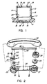
- Figure 2 is an exploded perspective view of a handset with the cartridge microphone transmitter and a receiver;
- Figure 3 is a cross-section on the line III-III of Figure 2 illustrating the assembly of transmitter to the housing of the handset;
- Figure 4 is a front face view of the transmitter housing
- Figure 5 is a view, on the interior surface of the transmitter housing with the transmitter assembly omitted.
- Figure 6 illustrates the performance curve desired for a telephone transmitter, and also the curve normally obtained with the cartridge microphone.
- a cartridge microphone is mounted in a hollow adaptor 11.
- the adaptor comprises a tubular housing part 12 with a front flange 13 which extends across one end of the tubular housing.
- a small hole 14 is provided in the flange 13.
- An annular rib 15 on the front face of the flange 13 defines a shallow recess 16 and a disc of acoustic resistance material 17 is fastened, as by welding or bonding, to the front face of the flange within the rib 15.
- the tubular housing has three slots 18 extending from the open back face of the adaptor.
- a deformable means 19 in the form of a shallow rib extends inwards at the back edge of the housing .
- the cartridge microphone is pushed into the housing deforming the wall outwards slightly as the cartridge is pushed past the rib 19, which then snaps in behind the cartridge.
- the front peripheral cover 20 of the cartridge is held firmly against a narrow ledge 21 extending around the inside of the housing.
- the ledge positions the front face of the cartridge a predetermined distance from the flange 13.
- Terminals 22 extend from the back surface of the cartridge for connection to the telephone circuitry.
- the cartridge microphone and adaptor is mounted on a small circuit board 25, which also carries a modular jack 26.
- This assembly is mounted in the transmitter housing of the handset, the housing indicated at 27.
- the adaptor rests on a tubular formation 28 extending up from the inner surface of the front face of the housing 27.
- the circuit board 25 rests on the pillar 29 and is fastened thereto by a screw 30.
- An annular seal 31 is positioned between the adaptor 11 and the tubular formation 28.
- the modular jack 26 is aligned with an aperture in the wall of the housing 27 for reception of a modular plug.
- Figure 2 also illustrates the rest of the handset, which comprises the front and back members 35 and 36, the front member also having a receiver housing at 37, the receiver indicated at 38 and a sealing washer at 19.
- the electrical connections from the receiver to the circuit board 25 is by two wires 40.
- the assembly of the microphone 10, adaptor 11, circuit board 25 and jack 26 is seen in cross-section in Figure 3.
- an arcuate slot 42 In the front face 41 of the transmitter housing 27, there is formed an arcuate slot 42.
- the slot is within the formation 28 and is wider at its rearward part, as seen in Figure 3.
- a groove 43 is formed in the front surface of the front face, continuing the narrower part of slot 42. However this groove does not extend through the front face.
- the groove 43 and slot 42 can be seen also in Figure 4 and the slot 42 is seen in Figure 5.
- the cartridge microphone does not have, of itself, a satisfactory response curve, and does not meet telephone standards.
- the response is modified by the mounting of the microphone.
- the cartridge is mounted in the adaptor with a particular volume between the face of the cartridge and the end of the adaptor.
- a small hole 14 covered with the acoustic material 17.
- the volume between the cartridge and the acoustic resistance is such as to provide the required damping.
- the acoustic resistance, from the acoustic material 27, is chosen to limit the peak to 14 dB rise from 1000 Hz.
- the size of the hole 14 is related to the acoustic resistance of the material 17.
- This latter volume referred to as the front volume, is sealed at the interface between adaptor 11 and the tubular formation 28 by the seal 31.
- Figure 6 illustrates the modified response curve obtained by the invention relative to an unmodified transducer.
- the chain dotted line 50 illustrates an unmodified transducer response curve and full line 51 illustrates the ideal or mean curve obtained with the invention.
- the dotted lines 52 illustrate a tolerance envelope acceptable for the curve 51.
Landscapes
- Engineering & Computer Science (AREA)
- Signal Processing (AREA)
- Telephone Set Structure (AREA)
- Details Of Audible-Bandwidth Transducers (AREA)
Claims (6)
- Mikrophonanordnung für ein Fernsprecher-Handteil, mit einem Kapsel-Elektret-Mikrophon (10), mit das Mikrophon einschließendem Mittel (11) mit einem rohrförmigen Gehäuse (12), das eine zylindrische Bohrung bestimmt, wobei sich eine Endwand (13) über ein vorderes Ende der Bohrung erstreckt und mit dem Mikrophon ein erstes Volumen bestimmt, eine Öffnung (14) sich durch die Wand (13) erstreckt, eine Schicht von akustischem Widerstandsmaterial (17) sich über die Öffnung erstreckt und mit ein zweites Volumen an der dem ersten Volumen abgelegenen Seite der Endwand bestimmendem Mittel (27, 28, 41), dadurch gekennzeichnet, daß der Adapter (11) weiter eine sich um die Bohrung mit einem vorbestimmten Abstand vom vorderen Ende der Bohrung erstreckende Leiste (21) umfaßt, daß deformierbares Mittel (19) sich an einem hinteren Ende in die Bohrung erstreckt, daß das Kapsel-Mikrophon (10) ein Schnapp-Einsetzteil des verformbaren Mittels (l9) ist und zwischen dem verformbaren Mittel (19) und der Leiste (21) gehalten ist, und daß das zweite Volumen ein umfaßtes Volumen mit einer vorbestimmten Resonanzfrequenz ist.
- Anordnung nach Anspruch 1, bei der das das zweite Volumen bestimmende Mittel gekennzeichnet ist durch ein Mikrophongehäuse (27) des Fernsprechhandgerätes, welches Mikrophongehäuse (27) eine Vorderfläche (41) besitzt und eine rohrförmige Ausbildung (28), die von einer Innenseite der Vorderfläche (41) absteht, wobei der Adapter (11) an eine innere Endfläche der rohrförmigen Ausbildung (28) angesetzt ist.
- Anordnung nach Anspruch 1 oder 2, bei der das die zylindrische Bohrung bestimmende rohrförmige Gehäuse gekennzeichnet ist durch eine Vielzahl von sich von dem hinteren Ende des rohrförmigen Gehäuses (12) aus erstreckenden Schlitzen (18) und eine flache Rippe, die sich am hinteren Ende nach innen erstreckt, wobei die flache Rippe das verformbare, sich in die Bohrung erstreckende Mittel (19) bildet.
- Anordnung nach Anspruch 2, gekennzeichnet durch einen sich durch die Vorderfläche (41) innerhalb der rohrförmigen Ausbildung (28) erstreckenden Schlitz (42).
- Anordnung nach Anspruch 4, dadurch gekennzeichnet, daß das erste Volumen von einer vorbestimmten Größe ist, um eine vorbestimmte Dämpfung zu schaffen, daß der akustische Widerstand des akustischen Widerstandsmaterials (17) von einer Höhe ist, die die Spitze auf einen 14 dB-Anstieg bei 1000 Hz begrenzt und das zweite Volumen von einer vorbestimmten Größe ist, um in Kombination mit den Schlitzen (42) eine Resonanz bei 3 000 Hz zu erzeugen.
- Anordnung nach einem der vorangehenden Ansprüche, gekennzeichnet durch eine von einer Vorderfläche der Endwand (13) koaxial mit der Bohrung abstehende Ringrippe (15), wobei die Schicht aus akustischem Widerstandsmaterial (17) an der Vorderfläche innerhalb der Ringrippe (15) angebracht ist.
Applications Claiming Priority (2)
| Application Number | Priority Date | Filing Date | Title |
|---|---|---|---|
| CA000449775A CA1202713A (en) | 1984-03-16 | 1984-03-16 | Transmitter assembly for a telephone handset |
| CA449775 | 1984-03-16 |
Publications (3)
| Publication Number | Publication Date |
|---|---|
| EP0161735A2 EP0161735A2 (de) | 1985-11-21 |
| EP0161735A3 EP0161735A3 (en) | 1987-03-11 |
| EP0161735B1 true EP0161735B1 (de) | 1991-02-27 |
Family
ID=4127423
Family Applications (1)
| Application Number | Title | Priority Date | Filing Date |
|---|---|---|---|
| EP85300571A Expired - Lifetime EP0161735B1 (de) | 1984-03-16 | 1985-01-28 | Mikrophonanordnung für Fernsprech-Handapparat |
Country Status (6)
| Country | Link |
|---|---|
| US (1) | US4594478A (de) |
| EP (1) | EP0161735B1 (de) |
| JP (1) | JPS60208147A (de) |
| KR (1) | KR920010408B1 (de) |
| CA (1) | CA1202713A (de) |
| DE (1) | DE3581833D1 (de) |
Cited By (1)
| Publication number | Priority date | Publication date | Assignee | Title |
|---|---|---|---|---|
| US7904123B2 (en) | 2006-09-15 | 2011-03-08 | Panasonic Corporation | Shield case and MEMS microphone having it |
Families Citing this family (37)
| Publication number | Priority date | Publication date | Assignee | Title |
|---|---|---|---|---|
| US4675903A (en) * | 1984-06-29 | 1987-06-23 | Wang Laboratories, Inc. | Telephone handset assembly |
| US4773091A (en) * | 1986-06-16 | 1988-09-20 | Northern Telecom Limited | Telephone handset for use in noisy locations |
| US4796288A (en) * | 1986-06-23 | 1989-01-03 | Northern Telecom Limited | Telephone handset with static discharge prevention |
| US4727583A (en) * | 1986-10-28 | 1988-02-23 | Motorola, Inc. | Telephone transducer with improved frequency response |
| WO1989004106A1 (en) * | 1987-10-28 | 1989-05-05 | Acs Communications, Inc. | Acoustic filter microphone cup |
| US5231659A (en) * | 1989-05-16 | 1993-07-27 | Alcatel Business Systems | Telephone handset with transducer assembly |
| US5042071A (en) * | 1990-01-18 | 1991-08-20 | Motorola, Inc. | Acoustic insulator for a telephone handset microphone |
| EP0562570B1 (de) * | 1992-03-25 | 2001-07-18 | Molex Incorporated | Piezoelektrischer elektroakustischer Wandler |
| DE9317982U1 (de) * | 1993-11-24 | 1994-03-10 | Siemens AG, 80333 München | Handapparat für eine Fernsprechstation |
| JP2780624B2 (ja) * | 1993-12-28 | 1998-07-30 | 日本電気株式会社 | 送話口構造 |
| CN1095622C (zh) * | 1996-10-11 | 2002-12-04 | 张炳林 | 一种防疫消毒电话筒 |
| US5890072A (en) * | 1996-11-07 | 1999-03-30 | Ericsson, Inc. | Radiotelephone having a non-resonant wave guide acoustically coupled to a microphone |
| GB2354393B (en) * | 1999-09-14 | 2003-11-12 | Mitel Corp | Complex acoustic path and gasket for use with microphones |
| JP2009247007A (ja) * | 2009-07-27 | 2009-10-22 | Panasonic Corp | シールドケースおよびこれを有するmemsマイクロホン |
| GB201204305D0 (en) * | 2012-03-12 | 2012-04-25 | Sec Dep For Business Innovation & Skills The | Microphone system and method |
| US9554207B2 (en) | 2015-04-30 | 2017-01-24 | Shure Acquisition Holdings, Inc. | Offset cartridge microphones |
| US9565493B2 (en) | 2015-04-30 | 2017-02-07 | Shure Acquisition Holdings, Inc. | Array microphone system and method of assembling the same |
| US10367948B2 (en) | 2017-01-13 | 2019-07-30 | Shure Acquisition Holdings, Inc. | Post-mixing acoustic echo cancellation systems and methods |
| EP3804356A1 (de) | 2018-06-01 | 2021-04-14 | Shure Acquisition Holdings, Inc. | Musterbildende mikrofonanordnung |
| US11297423B2 (en) | 2018-06-15 | 2022-04-05 | Shure Acquisition Holdings, Inc. | Endfire linear array microphone |
| EP3854108B1 (de) | 2018-09-20 | 2025-10-22 | Shure Acquisition Holdings, Inc. | Einstellbare keulenform für array-mikrofone |
| US11558693B2 (en) | 2019-03-21 | 2023-01-17 | Shure Acquisition Holdings, Inc. | Auto focus, auto focus within regions, and auto placement of beamformed microphone lobes with inhibition and voice activity detection functionality |
| JP7572964B2 (ja) | 2019-03-21 | 2024-10-24 | シュアー アクイジッション ホールディングス インコーポレイテッド | 阻止機能を伴うビーム形成マイクロフォンローブの自動集束、領域内自動集束、および自動配置 |
| EP3942842B1 (de) | 2019-03-21 | 2026-03-11 | Shure Acquisition Holdings, Inc. | Gehäuse und zugehörige konstruktionsmerkmale für mikrofone einer deckenanordnung |
| CN114051738B (zh) | 2019-05-23 | 2024-10-01 | 舒尔获得控股公司 | 可操纵扬声器阵列、系统及其方法 |
| US11302347B2 (en) | 2019-05-31 | 2022-04-12 | Shure Acquisition Holdings, Inc. | Low latency automixer integrated with voice and noise activity detection |
| EP4018680B1 (de) | 2019-08-23 | 2026-04-29 | Shure Acquisition Holdings, Inc. | Zweidimensionale mikrofonanordnung mit verbesserter richtcharakteristik |
| US12028678B2 (en) | 2019-11-01 | 2024-07-02 | Shure Acquisition Holdings, Inc. | Proximity microphone |
| US11552611B2 (en) | 2020-02-07 | 2023-01-10 | Shure Acquisition Holdings, Inc. | System and method for automatic adjustment of reference gain |
| WO2021243368A2 (en) | 2020-05-29 | 2021-12-02 | Shure Acquisition Holdings, Inc. | Transducer steering and configuration systems and methods using a local positioning system |
| US11785380B2 (en) | 2021-01-28 | 2023-10-10 | Shure Acquisition Holdings, Inc. | Hybrid audio beamforming system |
| US12452584B2 (en) | 2021-01-29 | 2025-10-21 | Shure Acquisition Holdings, Inc. | Scalable conferencing systems and methods |
| US12542123B2 (en) | 2021-08-31 | 2026-02-03 | Shure Acquisition Holdings, Inc. | Mask non-linear processor for acoustic echo cancellation |
| CN118216161A (zh) | 2021-10-04 | 2024-06-18 | 舒尔获得控股公司 | 联网自动混合器系统及方法 |
| EP4427465A1 (de) | 2021-11-05 | 2024-09-11 | Shure Acquisition Holdings, Inc. | Verteilter algorithmus zur automatischen mischung von sprache über drahtlose netzwerke |
| WO2023133513A1 (en) | 2022-01-07 | 2023-07-13 | Shure Acquisition Holdings, Inc. | Audio beamforming with nulling control system and methods |
| US12598261B2 (en) | 2022-09-28 | 2026-04-07 | Shure Acquisition Holdings, Inc. | Wideband doubletalk detection for optimization of acoustic echo cancellation |
Family Cites Families (10)
| Publication number | Priority date | Publication date | Assignee | Title |
|---|---|---|---|---|
| DE1208358B (de) * | 1964-01-08 | 1966-01-05 | Standard Elektrik Lorenz Ag | Elektrodynamischer Wandler der Fernmeldetechnik |
| NL7216501A (de) * | 1972-12-06 | 1974-06-10 | ||
| JPS6017191B2 (ja) * | 1977-12-30 | 1985-05-01 | アイホン株式会社 | 風雑音減衰効果を有するマイクロンホンユニツト |
| DE2831411C2 (de) * | 1978-07-17 | 1983-10-06 | Siemens Ag, 1000 Berlin Und 8000 Muenchen | Elektroakustischer Wandler mit mit piezoelektrischer Schicht versehener Membran |
| JPS5756640Y2 (de) * | 1978-09-30 | 1982-12-06 | ||
| US4291202A (en) * | 1979-09-25 | 1981-09-22 | Northern Telecom, Inc. | Telephone handset chassis and flexible printed circuit |
| GB2064265B (en) * | 1979-11-30 | 1984-01-11 | Pye Electronic Prod Ltd | Microphone unit |
| JPS57131195A (en) * | 1981-02-06 | 1982-08-13 | Aihon Kk | Noise preventing microphone device of band limiting type |
| US4424419A (en) * | 1981-10-19 | 1984-01-03 | Northern Telecom Limited | Electret microphone shield |
| US4449236A (en) * | 1982-04-08 | 1984-05-15 | Walker Equipment Corporation | Anti-side tone transmitter |
-
1984
- 1984-03-16 CA CA000449775A patent/CA1202713A/en not_active Expired
- 1984-07-26 US US06/634,690 patent/US4594478A/en not_active Expired - Lifetime
-
1985
- 1985-01-28 DE DE8585300571T patent/DE3581833D1/de not_active Expired - Fee Related
- 1985-01-28 EP EP85300571A patent/EP0161735B1/de not_active Expired - Lifetime
- 1985-03-07 JP JP60043830A patent/JPS60208147A/ja active Granted
- 1985-03-14 KR KR1019850001646A patent/KR920010408B1/ko not_active Expired
Cited By (1)
| Publication number | Priority date | Publication date | Assignee | Title |
|---|---|---|---|---|
| US7904123B2 (en) | 2006-09-15 | 2011-03-08 | Panasonic Corporation | Shield case and MEMS microphone having it |
Also Published As
| Publication number | Publication date |
|---|---|
| EP0161735A2 (de) | 1985-11-21 |
| US4594478A (en) | 1986-06-10 |
| JPH0436616B2 (de) | 1992-06-16 |
| CA1202713A (en) | 1986-04-01 |
| JPS60208147A (ja) | 1985-10-19 |
| KR850006809A (ko) | 1985-10-16 |
| DE3581833D1 (de) | 1991-04-04 |
| EP0161735A3 (en) | 1987-03-11 |
| KR920010408B1 (ko) | 1992-11-27 |
Similar Documents
| Publication | Publication Date | Title |
|---|---|---|
| EP0161735B1 (de) | Mikrophonanordnung für Fernsprech-Handapparat | |
| US4117275A (en) | Non-directional electret microphone with an air passage to balance pressures on opposite sides of the diaphragm | |
| US5204907A (en) | Noise cancelling microphone and boot mounting arrangement | |
| US4850016A (en) | Microphone | |
| US4697283A (en) | Telephone handset with integrated flux coil | |
| JP3538063B2 (ja) | 携帯無線機器の音響部品実装構造 | |
| GB2064265A (en) | Microphone unit | |
| US4636591A (en) | Integral transmitter and modular jack assembly for a telephone set | |
| US4449236A (en) | Anti-side tone transmitter | |
| US4506759A (en) | Loudspeaker enclosure arrangement for voice communication terminals | |
| CN213783352U (zh) | 一种有音腔结构的手机 | |
| JP3113832B2 (ja) | マイクロホン・ホルダー | |
| US5144656A (en) | Transmitter for communication equipment | |
| CN218550128U (zh) | 开放式耳机 | |
| EP1699258B1 (de) | Elektro-akustischer Wandler mit Halterung | |
| CN215420696U (zh) | 麦克风定位结构及耳机 | |
| CN210579139U (zh) | 一种高立体隔音降噪无线耳机 | |
| CN1004464B (zh) | 电话手机用送话器组件 | |
| CA1196717A (en) | Loudspeaker enclosure arrangement for voice communication terminals | |
| CN222073381U (zh) | 一种屏蔽杂音的受话器 | |
| JPS6125399A (ja) | マイクロホンユニツト | |
| CN216599703U (zh) | 声学结构及电子设备 | |
| CA1219096A (en) | Integral transmitter and modular jack assembly for a telephone set | |
| EP4622292A1 (de) | Wandlerhaltemodul für kopfhörer | |
| JP3354478B2 (ja) | エレクトレットコンデンサマイクロホン |
Legal Events
| Date | Code | Title | Description |
|---|---|---|---|
| PUAI | Public reference made under article 153(3) epc to a published international application that has entered the european phase |
Free format text: ORIGINAL CODE: 0009012 |
|
| AK | Designated contracting states |
Designated state(s): DE FR GB SE |
|
| PUAL | Search report despatched |
Free format text: ORIGINAL CODE: 0009013 |
|
| AK | Designated contracting states |
Kind code of ref document: A3 Designated state(s): DE FR GB SE |
|
| 17P | Request for examination filed |
Effective date: 19870813 |
|
| 17Q | First examination report despatched |
Effective date: 19890620 |
|
| GRAA | (expected) grant |
Free format text: ORIGINAL CODE: 0009210 |
|
| AK | Designated contracting states |
Kind code of ref document: B1 Designated state(s): DE FR GB SE |
|
| REF | Corresponds to: |
Ref document number: 3581833 Country of ref document: DE Date of ref document: 19910404 |
|
| ET | Fr: translation filed | ||
| PGFP | Annual fee paid to national office [announced via postgrant information from national office to epo] |
Ref country code: FR Payment date: 19911223 Year of fee payment: 8 |
|
| PLBE | No opposition filed within time limit |
Free format text: ORIGINAL CODE: 0009261 |
|
| STAA | Information on the status of an ep patent application or granted ep patent |
Free format text: STATUS: NO OPPOSITION FILED WITHIN TIME LIMIT |
|
| PGFP | Annual fee paid to national office [announced via postgrant information from national office to epo] |
Ref country code: SE Payment date: 19920122 Year of fee payment: 8 |
|
| 26N | No opposition filed | ||
| PGFP | Annual fee paid to national office [announced via postgrant information from national office to epo] |
Ref country code: DE Payment date: 19920228 Year of fee payment: 8 |
|
| PG25 | Lapsed in a contracting state [announced via postgrant information from national office to epo] |
Ref country code: SE Effective date: 19930129 |
|
| PG25 | Lapsed in a contracting state [announced via postgrant information from national office to epo] |
Ref country code: FR Effective date: 19930930 |
|
| PG25 | Lapsed in a contracting state [announced via postgrant information from national office to epo] |
Ref country code: DE Effective date: 19931001 |
|
| REG | Reference to a national code |
Ref country code: FR Ref legal event code: ST |
|
| EUG | Se: european patent has lapsed |
Ref document number: 85300571.8 Effective date: 19930810 |
|
| PGFP | Annual fee paid to national office [announced via postgrant information from national office to epo] |
Ref country code: GB Payment date: 19990128 Year of fee payment: 15 |
|
| PG25 | Lapsed in a contracting state [announced via postgrant information from national office to epo] |
Ref country code: GB Free format text: LAPSE BECAUSE OF NON-PAYMENT OF DUE FEES Effective date: 20000128 |
|
| GBPC | Gb: european patent ceased through non-payment of renewal fee |
Effective date: 20000128 |