EP0161803A2 - Blutfilter - Google Patents
Blutfilter Download PDFInfo
- Publication number
- EP0161803A2 EP0161803A2 EP85302556A EP85302556A EP0161803A2 EP 0161803 A2 EP0161803 A2 EP 0161803A2 EP 85302556 A EP85302556 A EP 85302556A EP 85302556 A EP85302556 A EP 85302556A EP 0161803 A2 EP0161803 A2 EP 0161803A2
- Authority
- EP
- European Patent Office
- Prior art keywords
- chamber
- blood
- filter element
- gas
- bubbles
- Prior art date
- Legal status (The legal status is an assumption and is not a legal conclusion. Google has not performed a legal analysis and makes no representation as to the accuracy of the status listed.)
- Granted
Links
Images


Classifications
-
- A—HUMAN NECESSITIES
- A61—MEDICAL OR VETERINARY SCIENCE; HYGIENE
- A61M—DEVICES FOR INTRODUCING MEDIA INTO, OR ONTO, THE BODY; DEVICES FOR TRANSDUCING BODY MEDIA OR FOR TAKING MEDIA FROM THE BODY; DEVICES FOR PRODUCING OR ENDING SLEEP OR STUPOR
- A61M1/00—Suction or pumping devices for medical purposes; Devices for carrying-off, for treatment of, or for carrying-over, body-liquids; Drainage systems
- A61M1/36—Other treatment of blood in a by-pass of the natural circulatory system, e.g. temperature adaptation, irradiation ; Extra-corporeal blood circuits
- A61M1/3621—Extra-corporeal blood circuits
- A61M1/3643—Priming, rinsing before or after use
-
- A—HUMAN NECESSITIES
- A61—MEDICAL OR VETERINARY SCIENCE; HYGIENE
- A61M—DEVICES FOR INTRODUCING MEDIA INTO, OR ONTO, THE BODY; DEVICES FOR TRANSDUCING BODY MEDIA OR FOR TAKING MEDIA FROM THE BODY; DEVICES FOR PRODUCING OR ENDING SLEEP OR STUPOR
- A61M1/00—Suction or pumping devices for medical purposes; Devices for carrying-off, for treatment of, or for carrying-over, body-liquids; Drainage systems
- A61M1/14—Dialysis systems; Artificial kidneys; Blood oxygenators ; Reciprocating systems for treatment of body fluids, e.g. single needle systems for hemofiltration or pheresis
- A61M1/32—Oxygenators without membranes
- A61M1/322—Antifoam; Defoaming
- A61M1/325—Surfactant coating; Improving wettability
-
- A—HUMAN NECESSITIES
- A61—MEDICAL OR VETERINARY SCIENCE; HYGIENE
- A61M—DEVICES FOR INTRODUCING MEDIA INTO, OR ONTO, THE BODY; DEVICES FOR TRANSDUCING BODY MEDIA OR FOR TAKING MEDIA FROM THE BODY; DEVICES FOR PRODUCING OR ENDING SLEEP OR STUPOR
- A61M1/00—Suction or pumping devices for medical purposes; Devices for carrying-off, for treatment of, or for carrying-over, body-liquids; Drainage systems
- A61M1/36—Other treatment of blood in a by-pass of the natural circulatory system, e.g. temperature adaptation, irradiation ; Extra-corporeal blood circuits
- A61M1/3621—Extra-corporeal blood circuits
- A61M1/3627—Degassing devices; Buffer reservoirs; Drip chambers; Blood filters
-
- A—HUMAN NECESSITIES
- A61—MEDICAL OR VETERINARY SCIENCE; HYGIENE
- A61M—DEVICES FOR INTRODUCING MEDIA INTO, OR ONTO, THE BODY; DEVICES FOR TRANSDUCING BODY MEDIA OR FOR TAKING MEDIA FROM THE BODY; DEVICES FOR PRODUCING OR ENDING SLEEP OR STUPOR
- A61M2205/00—General characteristics of the apparatus
- A61M2205/75—General characteristics of the apparatus with filters
- A61M2205/7536—General characteristics of the apparatus with filters allowing gas passage, but preventing liquid passage, e.g. liquophobic, hydrophobic, water-repellent membranes
-
- A—HUMAN NECESSITIES
- A61—MEDICAL OR VETERINARY SCIENCE; HYGIENE
- A61M—DEVICES FOR INTRODUCING MEDIA INTO, OR ONTO, THE BODY; DEVICES FOR TRANSDUCING BODY MEDIA OR FOR TAKING MEDIA FROM THE BODY; DEVICES FOR PRODUCING OR ENDING SLEEP OR STUPOR
- A61M2206/00—Characteristics of a physical parameter; associated device therefor
- A61M2206/10—Flow characteristics
- A61M2206/16—Rotating swirling helical flow, e.g. by tangential inflows
-
- Y—GENERAL TAGGING OF NEW TECHNOLOGICAL DEVELOPMENTS; GENERAL TAGGING OF CROSS-SECTIONAL TECHNOLOGIES SPANNING OVER SEVERAL SECTIONS OF THE IPC; TECHNICAL SUBJECTS COVERED BY FORMER USPC CROSS-REFERENCE ART COLLECTIONS [XRACs] AND DIGESTS
- Y10—TECHNICAL SUBJECTS COVERED BY FORMER USPC
- Y10S—TECHNICAL SUBJECTS COVERED BY FORMER USPC CROSS-REFERENCE ART COLLECTIONS [XRACs] AND DIGESTS
- Y10S128/00—Surgery
- Y10S128/03—Heart-lung
Definitions
- This invention relates to filters for use in the filtration of blood such as in cardiopulmonary bypass system used during open heart surgery.
- US-A 3,701,433 discloses a disposable blood filter employing a woven mesh having a pore size within the range of 25 to SO microns for removal of, inter alia, microemboli from artificially oxygenated blood prior to reintroduction into a patient during a cardiopulmonary bypass.
- filters are marketed by the present applicants and similar filters warketed by others have proven highly effective and beneficial and are now universally employed during surgery involving cardiopulmonary bypass.
- filters of the type disclosed in US-A 3,701,433 and used commercially include a port which may be employed to vent the gas but the port size typically is such that it is inadequate to vent a 100 per cent gas flow as when the blood feed to the pump is interrupted.
- the exterior chamber of a blood filter of the type shown in Fig. 4 of US-A 3,701,433 will fill with gas in approximately two seconds and, shortly therafter, air is likely to pass through the filter element and into a patient.
- a filter which quickly, automatically and safely vents all of the air presented at the upstream chamber, even in the event of a catastrophic failure is highly desirable both in terms of safety to the patient and economy in use of resources and personnel.
- apparatus for separating gas from blood before the blood passes through a filter
- said apparatus comprising, a housing defining a cylindrical chamber having a side wall and top and bottom walls, said bottom wall having an annular opening adapted to communicate with a filter, vent means in the centre portion of said top wall, a hydrophobic membrane covering said vent means whereby gas in the centre portion of said chamber can flow through the membrane and the vent means, and means including an inlet passage operable to introduce blood into said chamber generally tangentially of the side wall of the latter and direct the blood along a generally circular path at the periphery of the chamber and above said opening thereby to produce a centrifugal action which urges the blood outwardly toward said side wall while gas entrained in the blood is separated and moves to the centre portion of said chamber to flow out through said membrane and said vent means.
- apparatus for separating gas from blood before the blood passes through a filter comprising, a housing defining a chamber having top and bottom walls and a cylindrical side wall, said bottom wall having an annular opening adapted to communicate with a filter, an annular baffle disposed in said chamber concentrically with said side wall to define an annular channel overlying said opening, an inlet communicating with said channel through said side wall and disposed to direct blood into the channel tangentially of the side wall whereby the blood flows in a generally circular path in the channel and then out of said' chamber through said opening, said circular flow producing a centrifugal action which causes the blood to flow at the outer periphery of said channel while gas entrained in the blood separates and moves inwardly, said baffle having an opening to permit the gas to enter the centre portion of the chamber inside the baffle, venting means in the centre portion of said top wall to permit gas in the centre portion of said chamber to escape from the housing, and a hydrophobic membrane in said top wall covering said
- a blood filter assembly comprising, in combination, a housing having top, bottom and side walls and defining upper and lower chambers, at least said upper chamber being cylindrical, a cylindrical filter element disposed in said lower chamber and having a hollow interior, an outlet formed in said bottom wall and communicating with the interior of said filter element, the outer surface of said filter element being spaced from the side wall of said housing to define an annular space surrounding the filter element, means closing the top of said filter element whereby blood from said upper chamber enters said annular space and flows through the filter element from the outside to the interior and out through said outlet, an inlet communicating with said upper chamber through the side wall of said housing and disposed to direct the blood generally tangentially of the upper chamber, means for guiding the blood entering said upper chamber along a generally circular path at the periphery of the upper chamber to produce a centrifugal action which causes the blood to flow to the periphery of the upper chamber and then to said annular space while gas entrained in the blood separates and moves to the centre
- a blood filter comprising, in combination, a housing having top, bottom and side walls and defining upper and lower chambers, at least said upper chamber being cylindrical, a cylindrical filter element disposed in said lower chamber and having a hollow interior, an outlet formed in said housing and communicating with the interior of said filter element, the outer surface of said filter element being spaced from the side wall of said housing to define an annular space surrounding the filter element, means closing the top of said filter element whereby blood from said upper chambers enters said annular space and flows through the filter element from the outside to the interior and out through said outlet , an inlet communicating with said upper chamber through the side wall of said housing and disposed to direct the blood generaly tangentially of the upper chamber, an annular baffle disposed in said upper chamber concentrically with said side wall to define an annular channel for guiding blood which enters said upper chamber along a generally circular path at the periphery of the upper chamber, said circular flow producing a centrifugal action which causes the blood to flow to the perip
- apparatus for separating gas from blood comprising, a housing defining a first cylindrical chamber having top and bottom walls and a cylindrical side wall, said bottom wall having an annular opening extending at the periphery of said chamber, an annular baffle disposed in said chamber concentrically with said side wall to define an annular channel overlying said opening, an inlet communicating with said channel through said side wall and disposed to direct blood into the channel tangentially of the side wall whereby the blood flows in a generally circular path in the channel and then out of said chamber through said opening, said circular flow producing a centrifugal action which causes the blood to flow at the outer periphery of said channel while gas entrained in the blood separates and moves inwardly, said baffle having an opening to permit the gas to enter the centre portion of the chamber inside the baffle, venting means in the centre portion of said top wall to permit gas in the centre portion of said chamber to escape from the housing, a hydrophobic membrane in said top wall covering said venting means and
- a blood filter comprising, in combination, a housing having top, bottom and side walls and defining upper and lower cylindrical chambers, a cylindrical filter element disposed in said lower chamber and having a hollow interior, an outlet formed in said bottom wall and communicating with the interior of said filter element, the outer surface of said filter element being spaced from the side wall of said housing to define an annular space surrounding the filter element, means closing the top of said filter element whereby blood from said upper chamber enters said annular space and flows through the filter element from the outside to the interior and out through said outlet, an annulus of sponge material disposed in the upper end of said annular space and extending around the periphery of said housing, means in said upper chamber for directing blood to said sponge annulus whereby the blood flows through the latter to said annular space, said sponge annulus including means for causing gas bubbles in the blood to coalesce and form larger gas bubbles as the blood flows through said sponge annulus, means forming an annular passage between said sponge annulus and said filter element whereby said large
- apparatus for removing gas bubbles entrained in a liquid comprising, a housing defining a chamber having first and second passages opening through the upper end thereof, a body of sponge material disposed in said first passage, means for directing the flow of liquid into said chamber through said first passage and through said sponge body, and means in said sponge body operable to capture bubbles entrained in the liquid and to break the film between adjacent bubbles thereby to form larger bubbles which break away from said sponge body and rise through said second passage.
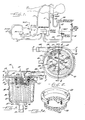
- the invention is embodied in an extracorporeal blood filter 10 such as is used in a cardiopulmonary bypass system during open heart surgery.
- Blood from the cardiovascular system of the patient flows through a tube 11 to an oxygenator 12 and oxygen also is delivered to the latter through a filter 13 and a tube 14 so that the oxygenator removes carbon dioxide from the blood and replaces it with oxygen.
- the perfusate is drawn from the oxygenator by a pump 15 through a tube 16 and is delivered to the filter 10 which removes microemboli including gas or air bubbles, fat emboli and aggregates formed from platelets, white blood cells, red blood cells and other debris.
- the filter is designed so that, the smallest size of particulate removed is in the range of 25 to 50 microns, 40 microns being customary.
- the filtered blood is returned to the cardiovascular system of the patient through a tube 17. Excess blood in the cavity in the patient where surgery is being performed is removed through a line 18 by a pump 19 and delivered to a cardiotomy reservoir 20. From the latter, the blood flows through a tube 21 to a filter 22, which may but need not be of the same construction as the filter 10, and then the blood flows through a tube 23 to the oxygenator 12 where it mixes with the blood from the patient's cardiovascular system.
- a bypass tube 24 around the filter 10 connects the tubes 16 and 17 and normally is closed by a clamp 25 which is released in an emergency when there is inadequate flow through the filter.
- the filter 10 includes an upright cylindrical filter element 26 (Figs. 3 and 4) disposed within generally cylindrical housing 27 which has an inlet passage 28 near its top and an outlet passage 29 at its bottom.
- the filter element includes a pleated screen made of a plastics material, polyesters and polyamides being examples, and the screen is wrapped around a perforated hollow core 30 (Fig. 4) made of a plastics material such as polypropylene.
- the filter element is a vertical cylinder with a central passage 31 extending along its axis and the upper ends of the filter element and the passage are closed by a cap 32 in the form of a disc moulded from a plastics material such as polypropylene.
- a similar cap 33 closes the lower end of the filter element and is formed with a central opening 34 (Fig. 4) at the end of the passage 31 in the filter element and aligned with the outlet passage 29 which, in this instance, extends through the bottom wall 35 of the housing.
- the filter element is disposed in a cylindrical chamber in the housing and is smaller in diameter than the side wall 36 of the chamber so that an annular space 37 is left between the side wall and the filter element.
- the housing 27 is made in two parts, that is, a body 38 and a cover 39 both moulded from a plastics material such as polystyrene.
- the body includes the bottom and side walls 35 and 36 and is substantially coextensive in depth with the height of the filter element 26.
- the cover is a shallow cylinder and includes a generally flat top wall 40 and a downturned cylindrical side wall 41 and the open upper end of the body is received in an annular channel 42 (Fig. 4) formed in a flange 43 on the lower end of the cover side wall 41.
- the cover and the body are joined at the channel as by bonding or by a spin weld.
- the inlet passage 28 is formed as a nipple 44 which is integral with the cover and receives the end of the tube 16.
- the outlet passage 29 is formed as a second nipple 45 which is moulded integrally with the housing body and projects axially down from a boss 46 on the underside of the bottom wall 35.
- An annular groove 47 in the inside of the boss receives an annular extension 48 which surrounds the opening 34 in the cap 33 and which centrally locates the filter element in the body.
- a chamber 49 located upstream of the filter element.
- this chamber is located in the cover 39 of the housing and is defined by the top wall 40 and the side wall 41 of the cover with the cap 32 on the top of the filter element serving as the bottom wall of the chamber.
- Some of the gas in the blood entering through the passage 28 separates from the blood while the blood is in the chamber 49 and is vented to the atmosphere.
- the blood then passes through an annular opening 50 (Fig. 4) in the bottom of the chamber to the space 37 around the filter element 26 and any remaining bubbles above a predetermined size, such as 40 microns, are removed by the filter element.
- a typical team of perfusionists using prior filters usually includes a technician who continually monitors the filter and is prepared to take appropriate steps as soon as the filter begins to fill with gas.
- the present invention contemplates the provision of a new and improved blood filter 10 in which a significant portion of the gas in the blood is separated from the blood while still in the upstream chamber 49 and this gas, even in gross amounts, is automatically vented to the atmosphere without reaching the filter element 26.
- means is provided for causing the blood to flow in a generally circular path around the periphery of the upstream chamber and produce a centrifugal action which causes the blood to stay at the peripheral portion while the air moves to the centre portion of the chamber and is vented through a hydrophobic membrane 51 (Figs. 4 and 5) in the top wall 40 of the chamber.
- the membrane is designed so that it has a capacity to vent a full flow of air whereby only blood containing microemboli which can be filtered is presented to the filter element.
- the means for causing the blood to flow in a circular path at the periphery of the upstream chamber 49 includes the nipple 44 which is arranged so that the inlet passage 28 is horizontal and opens through the side wall 41 of the cover 39 in a direction tangential to the side wall.
- the blood flows along the inside of the side wall at the periphery of the upstream chamber and, preferably, the circular flow of the blood at the periphery is maintained by an annular baffle 52 concentric with and spaced inwardly from the side wall. As shown in Figs.
- the baffle is formed integrally with the cover 29, extending downwardly from the top wall 40 thereof, and is generally coextensive with the side wall 41 so that it projects somewhat below the top of the filter element 26 and, with the side wall, forms a circular channel portion 53 in the chamber 49.
- the baffle extends for the major part of a full circle, beginning adjacent the inlet pasage, and, herein, it begins slightly in advance of the passage and extends for 300 degrees.
- the gas that is separated by centrifugal action moves against the outside of the baffle until it reaches an opening 55 defined by the ends of the baffle. At this point, the gas flows into the central portion 49a of the chamber 49 insidethe baffle (see arrows 56) and is vented through the membrane 51 while the blood flows down into the annular space 37 and through the filter element.
- the hydrophobic membrane 51 is circular and is large enough to overlie substantially all of the centre portion of the chamber 49 as defined by the baffle 52 so that the gas passes through the membrane and flows to vent holes 57 in the cover.
- the periphery of the membrane is clamped to a downwardly facing annular surface 58 (Fig. 6) on the underside of the cover by a plastics ring 59 which is bonded or otherwise suitably secured to the cover.
- a circular rib 61 upstanding from the" ring bears against the membrane to produce the clamping action.
- the ring also is used to support means for impeding and thus decreasing the circular flow in the centre portion of the chamber 49 thus facilitating the flow of gas through the membrane 51.
- this means comprises a plurality of flat vanes 60 which are moulded integrally with the ring and radiate from the centre theeof. The vanes underly the membrane and each is disposed in a vertical plane.
- vent holes 57 there are six vent holes 57 equally spaced angularly around the top wall 40 of the cover 39 with each associated with a radial strengthening rib 62 moulded integrally with the cover on top of the latter.
- the upper portion 63 of each vent hole is offset laterally from the lower portion 64 to prevent a pointed instrument from being accidentally inserted through the hole and puncturing the membrane 51.
- the latter is made up of a layer 65 stretched highly crystalline polytetrafluoroethylene, such as is known by the Registered Trade Mark TEFLON, heat sealed to a thin layer 66 of a substrate.
- the layer 65 is hydrophobic, that is, it is impermeable to liquid such as blood and is permeable to gas such as air.
- the layer €6 may be a thin porous paper such as the type conventionally used for making tea bags.
- the underside of the top wall of the cover is formed with a series of concentric circular ribs 67 which prevent the membrane from being pushed up flat against the top wall and thereby ensure a free flow of air to the vent holes.
- the cover may be provided with opening 68 (Fig. 2) which may be closed or which may be connected to any desired test apparatus.
- a body 69 of sponge material included in the assembly is treated with an antifoaming agent so as to capture small bubbles entrained in a liquid as the liquid is forced to flow down through the sponge and cause the bubbles to coalesce and form larger bubbles which break away from the sponge and rise against the flow of the liquid.
- the sponge body is interposed in the opening 50 between the upstream chamber 49 and the space 37 around the filter element 26 so that the blood leaving the chamber passes through the sponge with the result that at least some of the smaller gas bubbles remaining in the blood are removed before the blood reaches the filter element 26.
- the sponge also brakes the rotational flow of the blood and dissipates the centrifugal forces which otherwise would tend to force the air bubbles rather than the blood toward the filter element.
- the sponge body is a strip of medical grade polyurethene foam with approximately 8 to 20 pores per cm. (20 to 50 pores per inch), approximately 14 per cm. (35 per inch), being suitable for present purposes, and the strip is wrapped around inside the upper end portion of the housing body 38 at the annular opening 50 in the upper chamber 49.
- the antifoaming agent may be a compound of silicone and silica such as is sold as -Medical Antifoam A" by Dow Corning Mfg Co. and the sponge is treated by squeezing an inert liquid containing the compound through the sponge. As blood flows through the treated sponge, the silicone captivates small gas bubbles which, in turn, capture additional small bubbles while the silica breaks the film between two bubbles to create a larger one. Bubbles continue to grow in this manner until they become large enough to break away from the sponge and rise against the flow of blood.
- the sponge ring 69 is spaced radially outwardly of the filter element 26 by an annulus 70 to provide an annular passage 71 between the filter element and the annulus so that the larger bubbles produced by the sponge pass up through this passage to the centre portion of the chamber 49 and out through the membrane 51 with that gas which is being removed in the upstream chamber.
- the annulus 70 is perforated as indicated at 72 in Fig. 3a and the larger air bubbles as formed in the sponge pass with the blood through the perforations to the passage 71 with the bubbles rising to the chamber 49 and the blood flowing down to the space 37 around the filter element.
- the annulus 70 is a cylindrical ring moulded from the same plastics material as the body 27 and encircling the upper end of the filter element 26.
- the ring is concentric with the filter element and is the same diameter as the baffle 52 so as to constitute, in effect, an axial extension of the latter.
- the upper end portion of the housing body 38 is flared as indicated at 73 to provide an inclined shoulder 74 upon which the ring rests.
- the ring is captivated between the baffle 52 and the shoulder 74 and holds the sponge in place in the flared portion 73 of the housing body.
- blood from the oxygenator 12 enters the upstream chamber 49 tangentially through the inlet passsage 28 and flows in a circular path at the periphery of the cover 39 in the channel 53 as defined by the baffle 52 and the side wall 41 of the cover. That flow produces a centrifugal force which causes at least some of the gas bubbles in the blood, including any gross gas bubbles, to separate from the blood and move inwardly and through the opening 55 in the baffle to the central portion 49a of the upstream chamber.
- the gas is vented to the atmosphere through the membrane 51 and the vent holes 57 and this venting is aided by the vanes 60 on the ring 59 which slow the rotational flow of the bubbles and thereby permit a more rapid flow of the gas .through the membrane.
- the blood remaining in the channel 53 flows down through the sponge 69 and through perforated ring 70 and, while passing through the sponge, the smaller gas bubbles still remaining in the blood coalesce into larger bubbles. The latter together with the blood flow through the perforations 72 in the ring 70 to the passage 71 where the bubbles rise to the central portion of the upstream chamber 49 and are vented through the membrane 51.
- the rotational flow of the blood is braked so that the blood flows from the passage 71 to the outer surface of the filter element 26 without being impeded by gas bubbles.
- Any gas bubbles which remain in the blood at that time and which are larger than a predetermined size, such as 40 microns, are stopped by the filter element which also separates out other microemboli in the blood.
- the bubbles blocked by the filter element eventually coalesce with other bubbles to form larger bubbles which rise through the passage 71 to the chamber 49 for venting through the membrane.
- the filtered blood flows through the core 30 of the filter element and out through the outlet passage 29 for return to the patient.
Landscapes
- Health & Medical Sciences (AREA)
- Heart & Thoracic Surgery (AREA)
- Vascular Medicine (AREA)
- Hematology (AREA)
- Animal Behavior & Ethology (AREA)
- Engineering & Computer Science (AREA)
- Anesthesiology (AREA)
- Biomedical Technology (AREA)
- Veterinary Medicine (AREA)
- Life Sciences & Earth Sciences (AREA)
- Public Health (AREA)
- General Health & Medical Sciences (AREA)
- Emergency Medicine (AREA)
- Cardiology (AREA)
- Urology & Nephrology (AREA)
- External Artificial Organs (AREA)
- Infusion, Injection, And Reservoir Apparatuses (AREA)
- Degasification And Air Bubble Elimination (AREA)
Applications Claiming Priority (2)
| Application Number | Priority Date | Filing Date | Title |
|---|---|---|---|
| US06/599,585 US4572724A (en) | 1984-04-12 | 1984-04-12 | Blood filter |
| US599585 | 1984-04-12 |
Related Child Applications (1)
| Application Number | Title | Priority Date | Filing Date |
|---|---|---|---|
| EP89103278.1 Division-Into | 1985-04-11 |
Publications (3)
| Publication Number | Publication Date |
|---|---|
| EP0161803A2 true EP0161803A2 (de) | 1985-11-21 |
| EP0161803A3 EP0161803A3 (en) | 1986-12-03 |
| EP0161803B1 EP0161803B1 (de) | 1990-07-25 |
Family
ID=24400234
Family Applications (2)
| Application Number | Title | Priority Date | Filing Date |
|---|---|---|---|
| EP85302556A Expired - Lifetime EP0161803B1 (de) | 1984-04-12 | 1985-04-11 | Blutfilter |
| EP89103278A Expired - Lifetime EP0327136B1 (de) | 1984-04-12 | 1985-04-11 | Blutfilter |
Family Applications After (1)
| Application Number | Title | Priority Date | Filing Date |
|---|---|---|---|
| EP89103278A Expired - Lifetime EP0327136B1 (de) | 1984-04-12 | 1985-04-11 | Blutfilter |
Country Status (8)
| Country | Link |
|---|---|
| US (2) | US4572724A (de) |
| EP (2) | EP0161803B1 (de) |
| JP (1) | JPS60236662A (de) |
| AU (2) | AU588524B2 (de) |
| CA (1) | CA1236408A (de) |
| DE (2) | DE3578817D1 (de) |
| GB (1) | GB2157188B (de) |
| ZA (1) | ZA852726B (de) |
Cited By (2)
| Publication number | Priority date | Publication date | Assignee | Title |
|---|---|---|---|---|
| EP0803273A1 (de) * | 1996-04-27 | 1997-10-29 | Fresenius AG | Vorrichtung zum Abscheiden von Gasblasen aus Flüssigkeiten, insbesondere Blut |
| US8641657B2 (en) | 2006-12-01 | 2014-02-04 | Gambro Lundia Ab | Blood transfer chamber |
Families Citing this family (146)
| Publication number | Priority date | Publication date | Assignee | Title |
|---|---|---|---|---|
| US4572724A (en) * | 1984-04-12 | 1986-02-25 | Pall Corporation | Blood filter |
| SE452405B (sv) * | 1985-12-19 | 1987-11-30 | Gambro Cardio Ab | Hjert-lungsystem avsett for syresettning av en patients blod |
| US5203778A (en) * | 1986-02-18 | 1993-04-20 | Boehringer Laboratories | Process and apparatus for removal of insoluble fat from blood of a patient |
| US5354262A (en) * | 1986-02-18 | 1994-10-11 | Boehringer Laboratories | Apparatus for removal of insoluble fat from blood of a patient |
| US4676771A (en) * | 1986-03-31 | 1987-06-30 | Gelman Sciences, Inc. | Arterial blood filter |
| IT1189118B (it) * | 1986-05-12 | 1988-01-28 | Dideco Spa | Dispositivo per la filtrazione di sangue arterioso |
| US4955992A (en) * | 1987-06-26 | 1990-09-11 | Beckman Instruments, Inc. | Liquid degassing system |
| JPH01148266A (ja) * | 1987-12-04 | 1989-06-09 | Terumo Corp | 血液フィルター |
| AU105302S (en) | 1987-11-12 | 1989-10-11 | Terumo Corp | An intracardiac blood storing vessel |
| AU105300S (en) | 1987-11-12 | 1989-10-11 | Terumo Corp | An intracardiac/vein blood storing vessel |
| US4806135A (en) * | 1988-03-01 | 1989-02-21 | Siposs George G | Bubble trap for phase-separating gas bubbles from flowing liquids |
| JPH0657252B2 (ja) * | 1988-08-26 | 1994-08-03 | テルモ株式会社 | 貯血槽 |
| US5037457A (en) * | 1988-12-15 | 1991-08-06 | Millipore Corporation | Sterile hydrophobic polytetrafluoroethylene membrane laminate |
| US5019140A (en) * | 1988-12-21 | 1991-05-28 | W. L. Gore & Associates, Inc. | Irradiated expanded polytetrafluoroethylene composites, and devices using them, and processes for making them |
| US5061241A (en) * | 1989-01-19 | 1991-10-29 | Stephens Jr Harry W | Rapid infusion device |
| US4915713A (en) * | 1989-03-13 | 1990-04-10 | Beckman Instruments, Inc. | Liquid degassing system and method |
| US4964984A (en) * | 1989-06-14 | 1990-10-23 | Electromedics, Inc. | Blood filter |
| IT1231024B (it) * | 1989-07-31 | 1991-11-08 | Dideco Spa | Contenitore di sangue per apparecchio medicale |
| US5362406A (en) * | 1990-07-27 | 1994-11-08 | Pall Corporation | Leucocyte depleting filter device and method of use |
| GB2277886A (en) * | 1990-07-27 | 1994-11-16 | Pall Corp | Leucocyte depleting filter |
| DE69119683T2 (de) * | 1990-07-27 | 1996-10-02 | Pall Corp | Filtereinrichtung zur Entfernung von Leukozyten und Methode zur Verwendung |
| US5258127A (en) * | 1990-07-27 | 1993-11-02 | Pall Corporation | Leucocyte depleting filter device and method of use |
| WO1992021387A1 (en) * | 1991-05-31 | 1992-12-10 | Baxter International Inc. | Thromboresistant coating for defoaming applications |
| US5318510A (en) * | 1991-06-11 | 1994-06-07 | Deknatel Technology Corporation, Inc. | Collection device |
| DE69233634T2 (de) * | 1991-09-11 | 2007-05-16 | Pall Corp. | Gasplasma behandeltes, poröses Medium und Trennungsmethode unter Verwendung des Mediums |
| US5443743A (en) * | 1991-09-11 | 1995-08-22 | Pall Corporation | Gas plasma treated porous medium and method of separation using same |
| US5695489A (en) * | 1991-09-30 | 1997-12-09 | Baxter International Inc. | Blood filtering container |
| DE4321927C2 (de) * | 1993-07-01 | 1998-07-09 | Sartorius Gmbh | Filtereinheit mit Entgasungsvorrichtung |
| US5540841A (en) * | 1993-07-26 | 1996-07-30 | Pall Corporation | Cardioplegia filter and method for processing cardioplegia fluid |
| US5439587A (en) * | 1993-07-27 | 1995-08-08 | Millipore Corporation | Self priming filter apparatus |
| DE69432167T2 (de) * | 1993-10-28 | 2003-07-24 | Medrad, Inc. | System zur Kontrastmittelabgabe |
| EP0650738B1 (de) | 1993-10-28 | 2003-05-02 | Medrad, Inc. | System zur Administration von Flüssigkeiten bei mehreren Patienten |
| US5583742A (en) * | 1993-12-15 | 1996-12-10 | Alps Electric Co., Ltd. | Computer with protective cover having outwardly projecting cushioning portions |
| US5411705A (en) * | 1994-01-14 | 1995-05-02 | Avecor Cardiovascular Inc. | Combined cardiotomy and venous blood reservoir |
| CA2142413A1 (en) * | 1994-02-15 | 1995-08-16 | Wesley H. Verkarrt | Vortex gas elimination device |
| US5840026A (en) * | 1994-09-21 | 1998-11-24 | Medrad, Inc. | Patient specific dosing contrast delivery systems and methods |
| US5591344A (en) * | 1995-02-13 | 1997-01-07 | Aksys, Ltd. | Hot water disinfection of dialysis machines, including the extracorporeal circuit thereof |
| US5630946A (en) * | 1995-02-15 | 1997-05-20 | Pall Corporation | Method for processing a biological fluid including leukocyte removal in an extracorporeal circuit |
| US5989281A (en) | 1995-11-07 | 1999-11-23 | Embol-X, Inc. | Cannula with associated filter and methods of use during cardiac surgery |
| US5769816A (en) * | 1995-11-07 | 1998-06-23 | Embol-X, Inc. | Cannula with associated filter |
| US5800597A (en) * | 1997-01-21 | 1998-09-01 | Whatman Inc. | Integral coalescer filter-membrane device to provide a filtered gas stream and system employing such device |
| AU2729097A (en) * | 1996-04-12 | 1997-11-07 | Whatman, Inc. | Integral coalescer filter-membrane device and system |
| US5779674A (en) * | 1996-05-06 | 1998-07-14 | Mallinckrodt Medical, Inc. | Fluid gas removal drip chamber |
| AU3122197A (en) | 1996-05-14 | 1997-12-05 | Embol-X, Inc. | Aortic occluder with associated filter and methods of use during cardiac surgery |
| US6048331A (en) * | 1996-05-14 | 2000-04-11 | Embol-X, Inc. | Cardioplegia occluder |
| US6013061A (en) * | 1997-10-15 | 2000-01-11 | Microwave Medical Systems, Inc. | Automatic air eliminator |
| US5961700A (en) * | 1997-10-31 | 1999-10-05 | Sims Level 1 | Filter system for removal of gas and particulates from cellular fluids |
| US6019824A (en) * | 1998-06-09 | 2000-02-01 | Medisystems Technology Corporation | Bubble trap chamber |
| WO2000010673A1 (en) * | 1998-08-24 | 2000-03-02 | Nst Neurosurvival Technologies Ltd. | Apparatus and method for capturing particles with surface exposure of anionic phospholipids from biological fluids |
| IL125908A (en) | 1998-08-24 | 2005-05-17 | Nst Neurosurvival Technologies | Peptides and pharmaceutical compositions comprising same |
| IL131266A0 (en) | 1999-08-05 | 2001-01-28 | N S T Neurosurvival Technologi | Peptides and pharmaceutical compositions comprising same |
| US6337049B1 (en) * | 1998-08-28 | 2002-01-08 | Yehuda Tamari | Soft shell venous reservoir |
| US6267926B1 (en) * | 1998-10-08 | 2001-07-31 | Celgard Inc. | Device for removing entrained gases from liquids |
| US6224829B1 (en) * | 1998-12-30 | 2001-05-01 | Cadiovention, Inc. | Integrated blood oxygenator and pump system having means for reducing fiber breakage |
| US6302860B1 (en) | 1999-02-17 | 2001-10-16 | Medtronic, Inc. | Venous filter for assisted venous return |
| US6918887B1 (en) | 1999-02-17 | 2005-07-19 | Medtronic, Inc. | Venous filter for assisted venous return |
| US7108785B1 (en) * | 2000-11-06 | 2006-09-19 | Convergenza Handelsanstalt | Blood conditioning device |
| US6773670B2 (en) | 2001-02-09 | 2004-08-10 | Cardiovention, Inc. C/O The Brenner Group, Inc. | Blood filter having a sensor for active gas removal and methods of use |
| US6730267B2 (en) * | 2001-02-09 | 2004-05-04 | Cardiovention, Inc. | Integrated blood handling system having active gas removal system and methods of use |
| US20030075498A1 (en) * | 2001-06-01 | 2003-04-24 | Watkins Randolph H. | Hemodialyzer headers |
| US6623638B2 (en) | 2001-06-01 | 2003-09-23 | Baxter International Inc. | Hemodialyzer having improved dialysate perfusion |
| US20030057147A1 (en) * | 2001-09-24 | 2003-03-27 | Hemasure, Inc. | Filtration device and system for biological fluids |
| AU2003210841A1 (en) * | 2002-02-05 | 2003-09-02 | Cardiovention, Inc. | Blood filter having a sensor for active gas removal and methods of use |
| US20040063169A1 (en) * | 2002-02-05 | 2004-04-01 | Jeffrey Kane | Filtration assembly |
| ATE306305T1 (de) * | 2002-03-18 | 2005-10-15 | Parker Hannifin Corp | Mobiler tankfilter und filteranordnung |
| DE10224750A1 (de) | 2002-06-04 | 2003-12-24 | Fresenius Medical Care De Gmbh | Vorrichtung zur Behandlung einer medizinischen Flüssigkeit |
| WO2004000391A1 (en) * | 2002-06-24 | 2003-12-31 | Gambro Lundia Ab | Gas separation devices |
| EP1374929A1 (de) * | 2002-06-25 | 2004-01-02 | Jostra AG | Vorrichtung zur Elimination von Gasblasen |
| US7335334B2 (en) * | 2003-01-14 | 2008-02-26 | Medtronic, Inc. | Active air removal from an extracorporeal blood circuit |
| US7204958B2 (en) * | 2003-01-14 | 2007-04-17 | Medtronic, Inc. | Extracorporeal blood circuit air removal system and method |
| US7198751B2 (en) * | 2003-01-14 | 2007-04-03 | Medtronic, Inc. | Disposable, integrated, extracorporeal blood circuit |
| US7201870B2 (en) * | 2003-01-14 | 2007-04-10 | Medtronic, Inc. | Active air removal system operating modes of an extracorporeal blood circuit |
| US7189352B2 (en) * | 2003-01-14 | 2007-03-13 | Medtronic, Inc. | Extracorporeal blood circuit priming system and method |
| US7022099B2 (en) * | 2003-03-17 | 2006-04-04 | Cardiovention, Inc. | Extracorporeal blood handling system with automatic flow control and methods of use |
| US6908550B2 (en) * | 2003-05-21 | 2005-06-21 | Steven M. Silverstein | Filter bag |
| US20050029177A1 (en) * | 2003-08-04 | 2005-02-10 | Peterson David J. | Pool cleaner filter bag with zipper closure |
| US7097690B2 (en) * | 2003-10-10 | 2006-08-29 | Scimed Life Systems, Inc. | Apparatus and method for removing gasses from a liquid |
| CA2544612C (en) * | 2003-11-24 | 2011-12-20 | Gambro Lundia Ab | Degassing device and end-cap assembly for a filter including such a degassing device |
| US7744553B2 (en) | 2003-12-16 | 2010-06-29 | Baxter International Inc. | Medical fluid therapy flow control systems and methods |
| EP1557186B1 (de) | 2004-01-20 | 2010-11-17 | Sorin Group Deutschland GmbH | Automatisches Luftentsorgungssystem |
| US20060081524A1 (en) * | 2004-10-15 | 2006-04-20 | Amitava Sengupta | Membrane contactor and method of making the same |
| EP1812101A4 (de) | 2004-11-16 | 2014-04-23 | Medrad Inc | Modellierung von pharmazeutischer verbreitung |
| DK2902053T3 (da) | 2004-11-24 | 2017-11-13 | Bayer Healthcare Llc | Anordninger, systemer og fremgangsmåder til væskefremføring |
| US7935074B2 (en) * | 2005-02-28 | 2011-05-03 | Fresenius Medical Care Holdings, Inc. | Cassette system for peritoneal dialysis machine |
| US8197231B2 (en) | 2005-07-13 | 2012-06-12 | Purity Solutions Llc | Diaphragm pump and related methods |
| US7871391B2 (en) * | 2005-10-21 | 2011-01-18 | Fresenius Medical Care Holdings, Inc. | Extracorporeal fluid circuit |
| JP4855119B2 (ja) | 2006-03-28 | 2012-01-18 | テルモ株式会社 | フィルタ部材および人工肺 |
| US20080058712A1 (en) * | 2006-08-31 | 2008-03-06 | Plahey Kulwinder S | Peritoneal dialysis machine with dual voltage heater circuit and method of operation |
| EP2097835B1 (de) * | 2006-12-29 | 2018-05-30 | Bayer Healthcare LLC | Patientenbasierte parametergenerierungssysteme für medizinische injektionsverfahren |
| WO2008153831A2 (en) * | 2007-06-06 | 2008-12-18 | Luna Innovations Incorporated | Method and apparatus for acoustically enhanced removal of bubbles from a fluid |
| EP2170165B1 (de) | 2007-07-17 | 2018-12-05 | Bayer Healthcare LLC | Systeme zur bestimmung von parametern für ein verfahren zur schätzung der kardiopulmonalen funktion und zur flüssigkeitsabgabe |
| MX341535B (es) * | 2007-09-19 | 2016-08-24 | Fresenius Medical Care Holdings Inc | Estructura de ventilacion segura para circuito extracorporeo. |
| US7892197B2 (en) | 2007-09-19 | 2011-02-22 | Fresenius Medical Care Holdings, Inc. | Automatic prime of an extracorporeal blood circuit |
| CN102784422B (zh) | 2007-09-19 | 2015-05-06 | 弗雷塞尼斯医疗保健控股公司 | 透析系统及相关部件 |
| US8038886B2 (en) | 2007-09-19 | 2011-10-18 | Fresenius Medical Care North America | Medical hemodialysis container including a self sealing vent |
| US20090204078A1 (en) * | 2008-02-13 | 2009-08-13 | Boston Scientific Scimed, Inc. | Manifold and Valve Seal for Use with a Medical Device |
| US20110087187A1 (en) * | 2008-04-30 | 2011-04-14 | Gambro Lundia Ab | Hydrophobic deaeration membrane |
| US9421330B2 (en) | 2008-11-03 | 2016-08-23 | Bayer Healthcare Llc | Mitigation of contrast-induced nephropathy |
| US8663463B2 (en) * | 2009-02-18 | 2014-03-04 | Fresenius Medical Care Holdings, Inc. | Extracorporeal fluid circuit and related components |
| US8192401B2 (en) | 2009-03-20 | 2012-06-05 | Fresenius Medical Care Holdings, Inc. | Medical fluid pump systems and related components and methods |
| WO2011008858A1 (en) | 2009-07-15 | 2011-01-20 | Fresenius Medical Care Holdings, Inc. | Medical fluid cassettes and related systems and methods |
| US8720913B2 (en) | 2009-08-11 | 2014-05-13 | Fresenius Medical Care Holdings, Inc. | Portable peritoneal dialysis carts and related systems |
| US8500994B2 (en) * | 2010-01-07 | 2013-08-06 | Fresenius Medical Care Holdings, Inc. | Dialysis systems and methods |
| US9220832B2 (en) | 2010-01-07 | 2015-12-29 | Fresenius Medical Care Holdings, Inc. | Dialysis systems and methods |
| US8425780B2 (en) | 2010-03-11 | 2013-04-23 | Fresenius Medical Care Holdings, Inc. | Dialysis system venting devices and related systems and methods |
| CA2803169C (en) | 2010-06-24 | 2020-09-22 | Medrad, Inc. | Modeling of pharmaceutical propagation and parameter generation for injection protocols |
| US8523814B2 (en) * | 2010-09-28 | 2013-09-03 | Covidien Lp | Self-venting cannula assembly |
| DE102010053973A1 (de) | 2010-12-09 | 2012-06-14 | Fresenius Medical Care Deutschland Gmbh | Medizinisches Gerät mit einer Heizung |
| US8506684B2 (en) | 2010-12-15 | 2013-08-13 | Fresenius Medical Care Holdings, Inc. | Gas release devices for extracorporeal fluid circuits and related methods |
| EP2654825B1 (de) | 2010-12-20 | 2017-08-02 | Fresenius Medical Care Holdings, Inc. | Medizinische flüssigkeitskassetten sowie entsprechende systeme und verfahren |
| US9624915B2 (en) | 2011-03-09 | 2017-04-18 | Fresenius Medical Care Holdings, Inc. | Medical fluid delivery sets and related systems and methods |
| USD681210S1 (en) | 2011-04-07 | 2013-04-30 | Fresenius Medical Care Holdings, Inc. | Dialysis fluid line carrier |
| RU2477246C2 (ru) * | 2011-04-13 | 2013-03-10 | Открытое акционерное общество "Ракетно-космическая корпорация "Энергия" имени С.П. Королева" | Способ увода разгонного ракетного блока с траектории полета космического аппарата |
| AU2012254069B2 (en) | 2011-04-21 | 2015-10-08 | Fresenius Medical Care Holdings, Inc. | Medical fluid pumping systems and related devices and methods |
| US9375524B2 (en) | 2011-06-03 | 2016-06-28 | Fresenius Medical Care Holdings, Inc. | Method and arrangement for venting gases from a container having a powdered concentrate for use in hemodialysis |
| US9649436B2 (en) | 2011-09-21 | 2017-05-16 | Bayer Healthcare Llc | Assembly method for a fluid pump device for a continuous multi-fluid delivery system |
| US9186449B2 (en) | 2011-11-01 | 2015-11-17 | Fresenius Medical Care Holdings, Inc. | Dialysis machine support assemblies and related systems and methods |
| JP5997760B2 (ja) * | 2012-03-14 | 2016-09-28 | テルモ株式会社 | 検査用血液容器および採血器具 |
| HUE056182T2 (hu) | 2012-05-14 | 2022-01-28 | Bayer Healthcare Llc | Összeállítások és eljárások gyógyászati fluidum befecskendezési protokollok röntgencsõ-feszültség alapján történõ meghatározására |
| US9610392B2 (en) | 2012-06-08 | 2017-04-04 | Fresenius Medical Care Holdings, Inc. | Medical fluid cassettes and related systems and methods |
| US9500188B2 (en) | 2012-06-11 | 2016-11-22 | Fresenius Medical Care Holdings, Inc. | Medical fluid cassettes and related systems and methods |
| US9555379B2 (en) | 2013-03-13 | 2017-01-31 | Bayer Healthcare Llc | Fluid path set with turbulent mixing chamber, backflow compensator |
| US9561323B2 (en) | 2013-03-14 | 2017-02-07 | Fresenius Medical Care Holdings, Inc. | Medical fluid cassette leak detection methods and devices |
| US9433721B2 (en) | 2013-06-25 | 2016-09-06 | Fresenius Medical Care Holdings, Inc. | Vial spiking assemblies and related methods |
| US10117985B2 (en) | 2013-08-21 | 2018-11-06 | Fresenius Medical Care Holdings, Inc. | Determining a volume of medical fluid pumped into or out of a medical fluid cassette |
| ES3030489T3 (en) | 2015-01-09 | 2025-06-30 | Bayer Healthcare Llc | Multiple fluid delivery system with multi-use disposable set and features thereof |
| US9974942B2 (en) | 2015-06-19 | 2018-05-22 | Fresenius Medical Care Holdings, Inc. | Non-vented vial drug delivery |
| US9945838B2 (en) | 2015-12-17 | 2018-04-17 | Fresenius Medical Care Holdings, Inc. | Extracorporeal circuit blood chamber having an integrated deaeration device |
| EP3423130B1 (de) | 2016-03-03 | 2025-05-14 | Bayer Healthcare LLC | System und verfahren zur verbesserten fluidabgabe in injektorsystem für mehrere fluide |
| US11452804B2 (en) | 2016-08-01 | 2022-09-27 | Keith Gipson | System and method for reducing gaseous microemboli using venous blood bypass with filter |
| EP3538182A1 (de) | 2016-11-14 | 2019-09-18 | Bayer Healthcare LLC | Verfahren und systeme zur verifizierung des inhalts einer zur abgabe einer medizinischen flüssigkeit verwendeten spritze |
| US10391226B2 (en) | 2017-02-07 | 2019-08-27 | International Business Machines Corporation | Air bubble removal from extracorporeal blood via chemical entrapment of nitrogen |
| CN110809482B (zh) | 2017-08-31 | 2023-03-07 | 拜耳医药保健有限公司 | 流体注入器系统体积补偿系统和方法 |
| AU2018323442B2 (en) | 2017-08-31 | 2024-06-27 | Bayer Healthcare Llc | Fluid path impedance assessment for improving fluid delivery performance |
| AU2018326485B2 (en) | 2017-08-31 | 2024-01-04 | Bayer Healthcare Llc | Injector pressure calibration system and method |
| CN110891630B (zh) | 2017-08-31 | 2022-04-26 | 拜耳医药保健有限公司 | 驱动构件定位和流体注入器系统机械校准的系统和方法 |
| JP7493337B2 (ja) | 2017-08-31 | 2024-05-31 | バイエル・ヘルスケア・エルエルシー | 流体インジェクタシステムにおける動的圧力制御のための方法 |
| CA3097557A1 (en) | 2018-04-19 | 2019-10-24 | Bayer Healthcare Llc | System and method for air detection in fluid injector |
| CA3110859A1 (en) | 2018-08-28 | 2020-03-05 | Bayer Healthcare Llc | Fluid injector system, method of preventing fluid backflow, and computer program product |
| JP2021536278A (ja) | 2018-08-28 | 2021-12-27 | バイエル・ヘルスケア・エルエルシーBayer HealthCare LLC | 比性能を改善した流体注入器システム |
| WO2020139760A1 (en) | 2018-12-26 | 2020-07-02 | Frontline Advance Llc | Fire pit system |
| US20220088505A1 (en) * | 2019-01-29 | 2022-03-24 | Donaldson Company, Inc. | System and method for deaeration |
| USD914858S1 (en) * | 2019-02-25 | 2021-03-30 | Frontline Advance, Llc | Bonfire pit stand |
| EP4048423B1 (de) | 2019-10-23 | 2024-07-24 | Donaldson Company, Inc. | Filter- und entlüftungssystem |
| USD1043934S1 (en) | 2022-08-11 | 2024-09-24 | Solo Brands, Llc | Fire pit and stand |
| CN119793115B (zh) * | 2024-07-16 | 2026-01-02 | 大气(广东)科技发展有限公司 | 一种具有尾气除臭治理的氮氧化物处理装置 |
Family Cites Families (37)
| Publication number | Priority date | Publication date | Assignee | Title |
|---|---|---|---|---|
| US3115472A (en) * | 1959-09-14 | 1963-12-24 | Dow Corning | Solvent defoamers |
| US3523408A (en) * | 1968-04-02 | 1970-08-11 | Pall Corp | Gas separator |
| US3631654A (en) * | 1968-10-03 | 1972-01-04 | Pall Corp | Gas purge device |
| FR2106918A5 (de) * | 1970-09-29 | 1972-05-05 | Rhone Poulenc Sa | |
| US3701433A (en) * | 1970-11-10 | 1972-10-31 | Pall Corp | Filter for use in the filtration of blood |
| US3827562A (en) * | 1972-03-03 | 1974-08-06 | W Esmond | Filtering device |
| US3768653A (en) * | 1972-03-21 | 1973-10-30 | R Brumfield | Filtering cardiotomy reservoir |
| US3803810A (en) * | 1972-05-01 | 1974-04-16 | Pall Corp | Liquid-gas separator and filter |
| US4017279A (en) * | 1972-10-06 | 1977-04-12 | Intech, Inc. | Defoamer apparatus |
| US3935111A (en) * | 1973-04-06 | 1976-01-27 | Bentley Laboratories, Inc. | Device for removing blood microemboli |
| US3891416A (en) * | 1973-07-20 | 1975-06-24 | Baxter Laboratories Inc | Cardiotomy reservoir |
| US3993461A (en) * | 1973-07-20 | 1976-11-23 | Baxter Laboratories, Inc. | Cardiotomy reservoir |
| GB1492182A (en) * | 1973-11-07 | 1977-11-16 | Nippon Oil Co Ltd | Process for fluidised contact |
| US3854907A (en) * | 1973-12-10 | 1974-12-17 | Millipore Corp | Vented filter holder |
| NL7402355A (nl) * | 1974-02-21 | 1975-08-25 | Philips Nv | Huidelektrode. |
| US4046696A (en) * | 1974-04-19 | 1977-09-06 | Johnson & Johnson | Extracorporeal circuit blood filter |
| US4031891A (en) * | 1975-11-03 | 1977-06-28 | Baxter Travenol Laboratories, Inc. | Air eliminating filter |
| US4013072A (en) * | 1975-11-03 | 1977-03-22 | Baxter Travenol Laboratories, Inc. | Drip chamber for intravenous administration |
| US4113627A (en) * | 1976-01-28 | 1978-09-12 | Filtertek, Inc. | Process for making hermetically sealed filter units and filters made thereby |
| US4190426A (en) * | 1977-11-30 | 1980-02-26 | Baxter Travenol Laboratories, Inc. | Gas separating and venting filter |
| US4208193A (en) * | 1978-11-09 | 1980-06-17 | Baxter Travenol Laboratories, Inc. | Cardiotomy reservoir having two-stage defoaming means |
| US4326957A (en) * | 1978-07-21 | 1982-04-27 | Pall Corporation | Vented filter spigot for intravenous liquid administration apparatus |
| US4276170A (en) * | 1978-08-16 | 1981-06-30 | Critikon, Inc. | Vented flexible filtration device for use in administering parenteral liquids |
| US4265762A (en) * | 1978-11-24 | 1981-05-05 | Donaldson Company, Inc. | Filter assembly for use in the filtration of medical treatment liquids |
| US4298358A (en) * | 1979-01-11 | 1981-11-03 | Baxter Travenol Laboratories, Inc. | Gas separating and venting filter |
| FR2452936A1 (fr) * | 1979-04-03 | 1980-10-31 | Patrin Gerard | Dispositif de filtrage, notamment pour installation de circulation sanguine extra-corporelle |
| US4262668A (en) * | 1979-04-06 | 1981-04-21 | Baxter Travenol Laboratories, Inc. | Fixed volume infusion device |
| AU536655B2 (en) * | 1979-04-11 | 1984-05-17 | British Petroleum Company Limited, The | m |
| US4278084A (en) * | 1979-10-19 | 1981-07-14 | Baxter Travenol Laboratories, Inc. | Non air-blocking filter |
| US4344777A (en) * | 1980-01-07 | 1982-08-17 | Siposs George G | Directed flow bubble trap for arterial blood |
| US4336036A (en) * | 1981-01-08 | 1982-06-22 | Amf Incorporated | Filter and method of making same |
| FR2497682A1 (fr) * | 1981-01-12 | 1982-07-16 | Air Liquide | Procede et dispositif de traitement d'un fluide en vue d'en extraire une phase gazeuse |
| US4345919A (en) * | 1981-01-19 | 1982-08-24 | Texas Medical Products, Inc. | Degasser for biological fluids |
| US4411783A (en) * | 1981-12-23 | 1983-10-25 | Shiley Incorporated | Arterial blood filter with improved gas venting |
| DE3468170D1 (en) * | 1983-04-08 | 1988-02-04 | Shiley Inc | Blood filter |
| JPS59190307U (ja) * | 1983-06-01 | 1984-12-17 | 石川島播磨重工業株式会社 | 気泡除去装置 |
| US4572724A (en) * | 1984-04-12 | 1986-02-25 | Pall Corporation | Blood filter |
-
1984
- 1984-04-12 US US06/599,585 patent/US4572724A/en not_active Expired - Lifetime
-
1985
- 1985-04-11 AU AU41009/85A patent/AU588524B2/en not_active Ceased
- 1985-04-11 CA CA000478848A patent/CA1236408A/en not_active Expired
- 1985-04-11 DE DE8585302556T patent/DE3578817D1/de not_active Expired - Fee Related
- 1985-04-11 GB GB08509325A patent/GB2157188B/en not_active Expired
- 1985-04-11 EP EP85302556A patent/EP0161803B1/de not_active Expired - Lifetime
- 1985-04-11 EP EP89103278A patent/EP0327136B1/de not_active Expired - Lifetime
- 1985-04-11 ZA ZA852726A patent/ZA852726B/xx unknown
- 1985-04-11 DE DE8989103278T patent/DE3587271T2/de not_active Expired - Fee Related
- 1985-04-12 JP JP60078260A patent/JPS60236662A/ja active Granted
- 1985-11-04 US US06/794,559 patent/US4662906A/en not_active Expired - Lifetime
-
1989
- 1989-08-14 AU AU39913/89A patent/AU624630B2/en not_active Ceased
Cited By (4)
| Publication number | Priority date | Publication date | Assignee | Title |
|---|---|---|---|---|
| EP0803273A1 (de) * | 1996-04-27 | 1997-10-29 | Fresenius AG | Vorrichtung zum Abscheiden von Gasblasen aus Flüssigkeiten, insbesondere Blut |
| US5849065A (en) * | 1996-04-27 | 1998-12-15 | Fresenius Ag | Device for separating gas bubbles from fluids, in particular blood |
| US8641657B2 (en) | 2006-12-01 | 2014-02-04 | Gambro Lundia Ab | Blood transfer chamber |
| EP2099513B2 (de) † | 2006-12-01 | 2015-08-19 | Gambro Lundia AB | Bluttransferkammer |
Also Published As
| Publication number | Publication date |
|---|---|
| EP0161803A3 (en) | 1986-12-03 |
| GB2157188A (en) | 1985-10-23 |
| GB8509325D0 (en) | 1985-05-15 |
| JPH0458992B2 (de) | 1992-09-21 |
| AU3991389A (en) | 1989-11-30 |
| DE3578817D1 (de) | 1990-08-30 |
| US4662906A (en) | 1987-05-05 |
| EP0327136B1 (de) | 1993-04-14 |
| AU588524B2 (en) | 1989-09-21 |
| EP0161803B1 (de) | 1990-07-25 |
| GB2157188B (en) | 1988-05-18 |
| CA1236408A (en) | 1988-05-10 |
| US4572724A (en) | 1986-02-25 |
| ZA852726B (en) | 1986-05-28 |
| EP0327136A2 (de) | 1989-08-09 |
| EP0327136A3 (en) | 1989-10-11 |
| AU4100985A (en) | 1985-10-17 |
| DE3587271T2 (de) | 1993-09-23 |
| JPS60236662A (ja) | 1985-11-25 |
| DE3587271D1 (de) | 1993-05-19 |
| AU624630B2 (en) | 1992-06-18 |
Similar Documents
| Publication | Publication Date | Title |
|---|---|---|
| EP0327136B1 (de) | Blutfilter | |
| US4157965A (en) | Blood treating device | |
| CA1277561C (en) | Integrated membrane oxygenator, heat exchanger and reservoir | |
| EP0082721B1 (de) | Filter für arterielles Blut mit Gasabzug | |
| US5411705A (en) | Combined cardiotomy and venous blood reservoir | |
| US5362406A (en) | Leucocyte depleting filter device and method of use | |
| US4876066A (en) | Integrated membrane oxygenator, heat exchanger and reservoir | |
| US5039430A (en) | Method and apparatus for combining cardiotomy and venous blood | |
| JP4045068B2 (ja) | 動脈血用フィルタ | |
| JP4050808B2 (ja) | 静脈血リザーバ及び心臓切開血リザーバからなる体外回路用複合装置 | |
| US4164468A (en) | Blood treating device and method of operation | |
| US4208193A (en) | Cardiotomy reservoir having two-stage defoaming means | |
| US4345999A (en) | Apparatus for preventing the entry of air into an artificial organ | |
| US5849186A (en) | Integrated cardiotomy and venous blood reservoir | |
| US4297318A (en) | Blood oxygenator | |
| JPH059112B2 (de) | ||
| EP0478914A1 (de) | Filtereinrichtung zur Entfernung von Leukozyten und Methode zur Verwendung | |
| US4336224A (en) | Bubble oxygenator | |
| IE49063B1 (en) | Bubble oxygenator | |
| JP2003512137A (ja) | 流体制御導管 | |
| US4253967A (en) | Blood treating method | |
| JP3373252B2 (ja) | 貯血槽 | |
| JPS6145770A (ja) | 貯血槽 | |
| JPH027667B2 (de) | ||
| JPH02124170A (ja) | 貯血槽 |
Legal Events
| Date | Code | Title | Description |
|---|---|---|---|
| PUAI | Public reference made under article 153(3) epc to a published international application that has entered the european phase |
Free format text: ORIGINAL CODE: 0009012 |
|
| AK | Designated contracting states |
Designated state(s): CH DE FR IT LI SE |
|
| 17P | Request for examination filed |
Effective date: 19851119 |
|
| PUAL | Search report despatched |
Free format text: ORIGINAL CODE: 0009013 |
|
| AK | Designated contracting states |
Kind code of ref document: A3 Designated state(s): CH DE FR IT LI SE |
|
| 17Q | First examination report despatched |
Effective date: 19880701 |
|
| GRAA | (expected) grant |
Free format text: ORIGINAL CODE: 0009210 |
|
| ITF | It: translation for a ep patent filed | ||
| AK | Designated contracting states |
Kind code of ref document: B1 Designated state(s): CH DE FR IT LI SE |
|
| XX | Miscellaneous (additional remarks) |
Free format text: TEILANMELDUNG 89103278.1 EINGEREICHT AM 11/04/85. |
|
| REF | Corresponds to: |
Ref document number: 3578817 Country of ref document: DE Date of ref document: 19900830 |
|
| ET | Fr: translation filed | ||
| ITTA | It: last paid annual fee | ||
| PLBE | No opposition filed within time limit |
Free format text: ORIGINAL CODE: 0009261 |
|
| STAA | Information on the status of an ep patent application or granted ep patent |
Free format text: STATUS: NO OPPOSITION FILED WITHIN TIME LIMIT |
|
| 26N | No opposition filed | ||
| EAL | Se: european patent in force in sweden |
Ref document number: 85302556.7 |
|
| PGFP | Annual fee paid to national office [announced via postgrant information from national office to epo] |
Ref country code: DE Payment date: 20020417 Year of fee payment: 18 |
|
| PGFP | Annual fee paid to national office [announced via postgrant information from national office to epo] |
Ref country code: SE Payment date: 20030404 Year of fee payment: 19 |
|
| PGFP | Annual fee paid to national office [announced via postgrant information from national office to epo] |
Ref country code: FR Payment date: 20030408 Year of fee payment: 19 |
|
| PGFP | Annual fee paid to national office [announced via postgrant information from national office to epo] |
Ref country code: CH Payment date: 20030416 Year of fee payment: 19 |
|
| PG25 | Lapsed in a contracting state [announced via postgrant information from national office to epo] |
Ref country code: DE Free format text: LAPSE BECAUSE OF NON-PAYMENT OF DUE FEES Effective date: 20031101 |
|
| PG25 | Lapsed in a contracting state [announced via postgrant information from national office to epo] |
Ref country code: SE Free format text: LAPSE BECAUSE OF NON-PAYMENT OF DUE FEES Effective date: 20040412 |
|
| PG25 | Lapsed in a contracting state [announced via postgrant information from national office to epo] |
Ref country code: LI Free format text: LAPSE BECAUSE OF NON-PAYMENT OF DUE FEES Effective date: 20040430 Ref country code: CH Free format text: LAPSE BECAUSE OF NON-PAYMENT OF DUE FEES Effective date: 20040430 |
|
| EUG | Se: european patent has lapsed | ||
| REG | Reference to a national code |
Ref country code: CH Ref legal event code: PL |
|
| PG25 | Lapsed in a contracting state [announced via postgrant information from national office to epo] |
Ref country code: FR Free format text: LAPSE BECAUSE OF NON-PAYMENT OF DUE FEES Effective date: 20041231 |
|
| REG | Reference to a national code |
Ref country code: FR Ref legal event code: ST |