EP0161879A2 - Abdichtende Verkleidungsbefestigung - Google Patents
Abdichtende Verkleidungsbefestigung Download PDFInfo
- Publication number
- EP0161879A2 EP0161879A2 EP85303152A EP85303152A EP0161879A2 EP 0161879 A2 EP0161879 A2 EP 0161879A2 EP 85303152 A EP85303152 A EP 85303152A EP 85303152 A EP85303152 A EP 85303152A EP 0161879 A2 EP0161879 A2 EP 0161879A2
- Authority
- EP
- European Patent Office
- Prior art keywords
- plate
- edge
- lengthwise edge
- tubes
- saddles
- Prior art date
- Legal status (The legal status is an assumption and is not a legal conclusion. Google has not performed a legal analysis and makes no representation as to the accuracy of the status listed.)
- Withdrawn
Links
Images


Classifications
-
- F—MECHANICAL ENGINEERING; LIGHTING; HEATING; WEAPONS; BLASTING
- F22—STEAM GENERATION
- F22B—METHODS OF STEAM GENERATION; STEAM BOILERS
- F22B37/00—Component parts or details of steam boilers
- F22B37/02—Component parts or details of steam boilers applicable to more than one kind or type of steam boiler
- F22B37/36—Arrangements for sheathing or casing boilers
- F22B37/365—Casings of metal sheets, e.g. expansion plates, expansible joints
Definitions
- the invention relates to vapour generators and, more particularly, to a transition means for sealingly attaching a casing to a water-cooled membrane wall of the kind employed in vapour generators used to produce steam in electric or industrial power plants.
- membrane walls are composed of rows of vertically extending tubes, laterally spaced on centres wider than the tube diameter, connected by flat metal bars known as membranes. These bars are positioned 180° apart on the outside surface along the length of the tubes and continuously welded thereto and to adjacent tubes so as to form a continuous wall surface comprising an alternate succession of elongate circular tube surfaces and elongate flat membrane surfaces that are stepped inwardly of the outermost surface of the tubes defining intervening spaces between the tubes.
- the welds may be formed by various known means and are usually formed on both sides of the membrane wall.
- Metallic sheets or plates are attached to the membrane wall to form a gas-tight cased enclosure, for example, such as a windbox for housing the vapour generator's burners and for distribution of combustion air. It is essential that the casing be connected to the membrane wall in a gas-tight manner.
- connection of the casing and membrane wall is accomplished by the placement of short blocks of filler bar in the spaces between the tubes, adjacent the outer side of the membrane bars.
- An arrangement in which filler bars are welded in place between adjacent tubes is disclosed, for example, in United States Patent 3,357,408.
- the filler bars are horizontally and vertically seal welded between adjacent tubes to provide a flush, continuous surface transversely across the tubes and the intervening spaces.
- the casing is seal welded to the filler bars and tubes. This type of structural arrangement stiffens the tubes and restricts the ability of the tubes to expand and contract.
- a transition seal arrangement for sealingly connecting a casing to a fluid-cooled membrane wall of a vapour generator of the kind having a plurality of parallel, laterally spaced tubes and a plurality of membrane bars disposed between and weld united to adjacent ones of the tubes to define a wall surface with longitudinally extending circumferential surfaces and intervening planar surfaces, characterised in that an elongate plate is edge welded gas-tightly to the membrane wall and weld connected gas-tightly to the casing, the plate comprising a lengthwise edge having a plurality of arcuate saddles and protrusions formed in alternate succession there along with each of the saddles overlapping a circumferential portion of one of the tubes.
- Such a seal arrangement can more readily accommodate thermal differentials between a casing and a membrane wall between which it is connected.
- the saddles and the protrusions extend from the first lengthwise edge, substantially parallel to the tubes, for a distance less than the width of the plate and meld into a planar lower skirt of the plate.
- Each saddle preferably has a curvature with a radius at the first lengthwise edge which remains constant along the centreline of the s d uole through the length of the distance for which the saddle extends from the first lengthwise edge, and each of the protrusions has a depth which diminishes as the distance from the lengthwise edge increases.
- the plate accordingly, is preferably provided with a second lengthwise edge which is parallel to the first lengthwise edge, and is a straight edge. A lateral surface portion of the plate adjacent the first lengthwise edge, preferably abuts against a portion of the tube surface and the membrane surface.
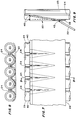
- Figure 1 a perspective illustration of a portion of a transition seal plate 20, a section of a membrane wall 21 and a casing 22.
- the membrane wall 21 is composed of tubes 23, only several of which are shown for clarity, arranged in a row with their longitudinal axes in parallel.
- the tubes 23 are interconnected by a plurality of flat elongate bars 24.
- the bars 24, also referred to as membranes, are welded to each tube 23 at surfaces approximately 180 apart.
- the sides of the bars 24 are continuously welded to the tubes 23 and are disposed along a common plane extending through the row. The plane is indented relative to the outer surface of the tubes and extends through the centreline of each tube within the row.
- each face of the wall comprises a surface with longitudinally extending semi-circular or circumferential surfaces and intervening planar surfaces.
- the plate 20 is a generally rectangular sheet of metal having mutually opposing lengthwise upper and lower edges 25 and 26 and widthwise edges 27 and 28.
- the upper lengthwise edge 25 follows a generally corrugated contour and includes a plurality of arcuate saddles 30 meeting in protrusions 31 which are formed in alternate succession at equally spaced intervals along the edge 25.
- the saddles 30 are shaped to conform to the shape of the tubes 23.
- the protrusions 31 are designed to project into the spaces between the adjacent tubes and, at the edge 25, have a depth sufficient to allow each protrusion 31 to abut against a respective one of the membrane bars 24.
- the lower lengthwise edge 26 is a straight edge.
- the saddles 30 and protrusions 31 extend a distance 32 from the upper edge 25.
- the depth "d" of the protrusions diminishes and each saddle and protrusion gradually tapers into the plane of the bottom collar or skirt of the plate 20, as best shown in Figures 4-6, as the distance from the upper edge increases.
- the radius of curvature "r" of the saddle 30 at the upper edge 25 is constant along the vertical centreline of the saddle 30 but the curvature of the saddle 30 on each side of the centreline diminishes toward the plane of the flat portion of the plate 20 as the distance from the upper edge 25 increases.
- a plate 20 may be exemplified by the following dimensional data.
- a transition plate for a membrane wall having 63.5mm (2 1/2 inch) outer diameter tubes on 76.2mm (3 inch) centres would comprise a steel sheet having a length of approximately 762mm (2 1/2 feet) from the edge 27 to the edge 28 and a width of approximately 230mm (9 inches) from the edge 25 to the edge 26.
- the first 12.2mm (1/2 inch) from the upper edge 25 of the plate would be designed to abut against the surfaces of the membrane wall.
- the saddles and protrusions would extend an overall length of 177.8mm (7 inches) from the upper edge 25 and the remaining 50.8mm (2 inches) of the plate, to the lower edge 26, would be flat.
- the radius of curvature of the saddles 30, at the upper edge 25, would be approximately 33mm (1 5/16 inches).
- a seal plate 20 is mounted to a membrane wall 21 as shown in Figures 7 and 8.
- the saddles 30 and tubes 23 are aligned so that the saddles 30 overlap the tubes and the protrusions project into the spaces between the tubes.
- a lateral wall portion of the plate 20 adjacent to the upper edge abuts against the membrane wall.
- the saddles 30 abut against the tubes 23 and the protrusions 31 abut against the membranes 24.
- the plate 20 is integrally attached to the membrane wall 21 by a weld 40 formed along the upper lengthwise edge 25 of the plate 20.
- a number of plates 20 may be connected along their respective widthwise edges 27, 28 by the formation of a weld 41 which extends from the upper edge 25 to the lower edge 26 as is schematically illustrated in Figure 10.
- the plates 20, therefore, can be arranged continuously about the periphery of the vapour generator.
- the casing 22 is seal welded along its upper edge to the plate 20 along a weld line 42 between the lower edge 26 and the point at which the saddles and the protrusions meld into the plane of the planar bottom portion or skirt of the plate 20.
- the casing is not directly welded to any portion of the membrane wall and the plate 20 is only welded along a horizontally extending weld line.
- the corrugated upper edge 25 which follows the tube contour is capable of more readily accommodating the unequal expansion resulting from thermal differentials between the membrane wall and the casing, than the more rigid prior art filler bar method of attaching the casing and membrane wall.
Landscapes
- Engineering & Computer Science (AREA)
- Physics & Mathematics (AREA)
- Thermal Sciences (AREA)
- Mechanical Engineering (AREA)
- General Engineering & Computer Science (AREA)
- Separation Using Semi-Permeable Membranes (AREA)
- Measuring Fluid Pressure (AREA)
- Gasket Seals (AREA)
Applications Claiming Priority (2)
| Application Number | Priority Date | Filing Date | Title |
|---|---|---|---|
| US607092 | 1984-05-04 | ||
| US06/607,092 US4538550A (en) | 1984-05-04 | 1984-05-04 | Casing seal attachment |
Publications (2)
| Publication Number | Publication Date |
|---|---|
| EP0161879A2 true EP0161879A2 (de) | 1985-11-21 |
| EP0161879A3 EP0161879A3 (de) | 1986-10-08 |
Family
ID=24430774
Family Applications (1)
| Application Number | Title | Priority Date | Filing Date |
|---|---|---|---|
| EP85303152A Withdrawn EP0161879A3 (de) | 1984-05-04 | 1985-05-02 | Abdichtende Verkleidungsbefestigung |
Country Status (8)
| Country | Link |
|---|---|
| US (1) | US4538550A (de) |
| EP (1) | EP0161879A3 (de) |
| JP (1) | JPS60240903A (de) |
| AU (1) | AU4197385A (de) |
| BR (1) | BR8501784A (de) |
| CA (1) | CA1259007A (de) |
| ES (1) | ES8606608A1 (de) |
| IN (1) | IN162919B (de) |
Cited By (1)
| Publication number | Priority date | Publication date | Assignee | Title |
|---|---|---|---|---|
| CN105026523A (zh) * | 2013-03-07 | 2015-11-04 | 斗山重工业株式会社 | 膜式水冷壁制造方法,用于制造输送导管的弯管装置及利用其的输送导管制造方法 |
Families Citing this family (3)
| Publication number | Priority date | Publication date | Assignee | Title |
|---|---|---|---|---|
| US4657069A (en) * | 1986-03-31 | 1987-04-14 | Deere & Company | Heat exchange tube retainer |
| US6044805A (en) * | 1999-05-06 | 2000-04-04 | The Babcock & Wilcox Company | Wall protection from downward flowing solids |
| US20120266826A1 (en) * | 2011-04-22 | 2012-10-25 | Saint-Gobain Ceramics & Plastics, Inc. | System, method and apparatus for thermally conductive refractory tiles for waste to energy boiler walls |
Family Cites Families (12)
| Publication number | Priority date | Publication date | Assignee | Title |
|---|---|---|---|---|
| US1741718A (en) * | 1925-11-27 | 1929-12-31 | Babcock & Wilcox Co | Furnace wall and baffle |
| US3357408A (en) * | 1965-08-19 | 1967-12-12 | Babcock & Wilcox Co | Vapor generating apparatus |
| FR1474870A (fr) * | 1966-01-27 | 1967-03-31 | Paroi tubulaire étanche | |
| FR1481350A (fr) * | 1966-05-25 | 1967-05-19 | Combustion Eng | Supports de tubes, notamment de tubes de plafonds horizontaux en particulier pour réchauffeur de fluide |
| US3479994A (en) * | 1968-02-01 | 1969-11-25 | Babcock & Wilcox Co | Enclosure for vapor generator |
| US3838665A (en) * | 1972-06-19 | 1974-10-01 | Goetaverken Angteknik Ab | Furnace wall containing spaced, parallel water tubes and blocks mounted thereon |
| US3799123A (en) * | 1972-06-30 | 1974-03-26 | Foster Wheeler Corp | Device for connecting a boiler to a penthouse |
| DE2251396B2 (de) * | 1972-10-19 | 1979-12-06 | Borsig Gmbh, 1000 Berlin | Brennkammer eines Dampferzeugers |
| DE2621189C3 (de) * | 1976-05-13 | 1980-02-21 | Balcke-Duerr Ag, 4030 Ratingen | Vorrichtung zur Aufhängung einer Rohrwand |
| DE2740937A1 (de) * | 1977-09-10 | 1979-03-22 | Bosch Gmbh Robert | Waermeuebertrager fuer fluessigkeitserhitzer |
| JPS54132003A (en) * | 1978-04-04 | 1979-10-13 | Mitsubishi Heavy Ind Ltd | Tension plate fitting method |
| CH634905A5 (de) * | 1978-12-20 | 1983-02-28 | Sulzer Ag | Dampferzeugerwand. |
-
1984
- 1984-05-04 US US06/607,092 patent/US4538550A/en not_active Expired - Lifetime
-
1985
- 1985-03-28 IN IN266/DEL/85A patent/IN162919B/en unknown
- 1985-04-15 BR BR8501784A patent/BR8501784A/pt unknown
- 1985-04-16 JP JP60079451A patent/JPS60240903A/ja active Granted
- 1985-05-02 EP EP85303152A patent/EP0161879A3/de not_active Withdrawn
- 1985-05-03 ES ES542816A patent/ES8606608A1/es not_active Expired
- 1985-05-03 AU AU41973/85A patent/AU4197385A/en not_active Abandoned
- 1985-05-03 CA CA000480742A patent/CA1259007A/en not_active Expired
Cited By (1)
| Publication number | Priority date | Publication date | Assignee | Title |
|---|---|---|---|---|
| CN105026523A (zh) * | 2013-03-07 | 2015-11-04 | 斗山重工业株式会社 | 膜式水冷壁制造方法,用于制造输送导管的弯管装置及利用其的输送导管制造方法 |
Also Published As
| Publication number | Publication date |
|---|---|
| BR8501784A (pt) | 1985-12-10 |
| US4538550A (en) | 1985-09-03 |
| ES542816A0 (es) | 1986-04-16 |
| JPS60240903A (ja) | 1985-11-29 |
| ES8606608A1 (es) | 1986-04-16 |
| EP0161879A3 (de) | 1986-10-08 |
| AU4197385A (en) | 1985-11-07 |
| JPH0341721B2 (de) | 1991-06-25 |
| CA1259007A (en) | 1989-09-05 |
| IN162919B (de) | 1988-07-23 |
Similar Documents
| Publication | Publication Date | Title |
|---|---|---|
| US4809645A (en) | Device for shielding boiler baffles, in particular for refuse incinerator furnaces, and a method for the constructon of said device | |
| US4688631A (en) | Plate heat exchanger | |
| US4344480A (en) | Support for heat exchange tubes | |
| CA1094900A (en) | Support for heat exchange tubes | |
| US7275503B2 (en) | Heat transfer tube panel module and method of constructing exhaust heat recovery boiler using the module | |
| CA1138850A (en) | Excavation or trenching plate | |
| EP0161879A2 (de) | Abdichtende Verkleidungsbefestigung | |
| US4347810A (en) | Combustion chamber wall | |
| JPS6129677B2 (de) | ||
| US4721069A (en) | Termination for boiler casing expansion element | |
| CH668293A5 (it) | Silenziatore di scarico per turbine a gas di grande potenza. | |
| US4706614A (en) | Device for suspending a bundle of horizontal tubes in a vertical plane and method of fabricating the device | |
| US4499860A (en) | Furnace buckstay design | |
| US4410487A (en) | Core baffle or enclosure and method of fabricating the same | |
| EP0246779A1 (de) | Wärmeaustauscher | |
| KR102189759B1 (ko) | 보일러 튜브 배열체를 위한 핀 그리고 그러한 핀을 포함하는 조립체 | |
| US6041854A (en) | Water cooled panel | |
| US4874041A (en) | Bar support shim and method | |
| GB1592125A (en) | Heat exchanger for liquid heaters | |
| US4749117A (en) | Tube sheet welding | |
| CA1271376A (en) | Spiral to vertical furnace tube transition | |
| US3457903A (en) | Furnace floor arrangement | |
| CN214922439U (zh) | 一种工件坡口切割平台 | |
| SE452520B (sv) | Tank for inneslutning av en oljekyld, elektromagnetisk induktionsanordning | |
| SE458729B (sv) | Spaltfoersett braensleelement foer en kaernreaktor, saerskilt en kokvattenreaktor |
Legal Events
| Date | Code | Title | Description |
|---|---|---|---|
| PUAI | Public reference made under article 153(3) epc to a published international application that has entered the european phase |
Free format text: ORIGINAL CODE: 0009012 |
|
| AK | Designated contracting states |
Designated state(s): DE FR GB IT |
|
| PUAL | Search report despatched |
Free format text: ORIGINAL CODE: 0009013 |
|
| AK | Designated contracting states |
Kind code of ref document: A3 Designated state(s): DE FR GB IT |
|
| 17P | Request for examination filed |
Effective date: 19870221 |
|
| 17Q | First examination report despatched |
Effective date: 19870722 |
|
| STAA | Information on the status of an ep patent application or granted ep patent |
Free format text: STATUS: THE APPLICATION IS DEEMED TO BE WITHDRAWN |
|
| 18D | Application deemed to be withdrawn |
Effective date: 19871130 |
|
| RIN1 | Information on inventor provided before grant (corrected) |
Inventor name: HALLER, KURT H. Inventor name: KIDALOSKI, RAYMOND G. |