EP0161891A2 - Temperatursteuerungssystem - Google Patents
Temperatursteuerungssystem Download PDFInfo
- Publication number
- EP0161891A2 EP0161891A2 EP85303198A EP85303198A EP0161891A2 EP 0161891 A2 EP0161891 A2 EP 0161891A2 EP 85303198 A EP85303198 A EP 85303198A EP 85303198 A EP85303198 A EP 85303198A EP 0161891 A2 EP0161891 A2 EP 0161891A2
- Authority
- EP
- European Patent Office
- Prior art keywords
- temperature
- heat source
- timer
- control signal
- error
- Prior art date
- Legal status (The legal status is an assumption and is not a legal conclusion. Google has not performed a legal analysis and makes no representation as to the accuracy of the status listed.)
- Withdrawn
Links
Images

Classifications
-
- G—PHYSICS
- G05—CONTROLLING; REGULATING
- G05D—SYSTEMS FOR CONTROLLING OR REGULATING NON-ELECTRIC VARIABLES
- G05D23/00—Control of temperature
- G05D23/19—Control of temperature characterised by the use of electric means
- G05D23/20—Control of temperature characterised by the use of electric means with sensing elements having variation of electric or magnetic properties with change of temperature
-
- G—PHYSICS
- G05—CONTROLLING; REGULATING
- G05D—SYSTEMS FOR CONTROLLING OR REGULATING NON-ELECTRIC VARIABLES
- G05D23/00—Control of temperature
- G05D23/19—Control of temperature characterised by the use of electric means
- G05D23/1906—Control of temperature characterised by the use of electric means using an analogue comparing device
- G05D23/1909—Control of temperature characterised by the use of electric means using an analogue comparing device whose output amplitude can only take two discrete values
Definitions
- the present invention relates primarily to temperature control in central heating systems, though it is concerned with the control system rather than the central heating system as such and may therefore be applicable to other process variable control systems.
- One method of achieving cycling is to use a room thermostat with a simple two point control with a differential between the two switching temperatures, that at which the thermostat output changes from ON (calling for heat) to OFF and that (slightly lower) at which the output changes back from OFF to ON.
- a problem with this method is that the cycle rate is dependent on the particular conditions of the room being heated - a large radiator will give rapid heating, whereas a large well-insulated room with a small radiator will heat up slowly. Control of cycle time can be achieved to a limited extent by adjustment of the differential of the thermostat on site.
- Another method of achieving cycling is to use a room thermostat type device with an anticipator, which is a small heating resistor build into the thermostat and which is turned on with the heat source.
- This system offers proportional control.
- this sytem has limited applicability, and suffers from the control point error common to all proportional controllers, in that the mean on time is controlled by the error between the actual and desired temperatures so that a finite error must exist for the mean on time to be different from the zero error value.
- the present invention provides a control system which is able to utilize full PID (proportional integral and differential) control.
- a target temperature TT for delivered water is defined in terms of the set point error temperature TD as follows:
- a timer means is started when the heat source is turned on, and the heat source is not allowed to turn on again until the timer period has expired. If the heat source is still on when the timer period expires and does not go off until after then, or if it has turned off but the error temperature has not crossed its differential band by the time the timer period expires, then the heat source will be turned on again when the error signal passes outside the differential band in the usual way and the operation will not be affected by the timer. However, if the heat source has been turned off and the error temperature has crossed the differential band before the timer period expires, the heat source will be prevented from turning on at the normal time. Thus the system sets a lower limit to the cycle time, i.e. an upper limit to the cycle rate.
- a heat source HS, water pump P, and radiator R are connected in a water loop.
- the radiator R is in a room 10, which is the space to be heated.
- the water loop includes a water temperature sensor 11, which produces a signal TDW indicative of the delivered water temperature.
- the room 10 contains a room temperature sensor 12, which produces a signal TA indicative of the actual room temperature.
- the setpoint temperature TSP and the actual temperature TA are fed to a PID unit 14, which processes them to generate a target temperature signal TT in accordance with the equation above.
- This unit may comprise a difference circuit 15 which feeds an adder circuit 19 via three parallel paths, namely a differentiating circuit 16, a proportional circuit 17, and an integrating circuit 18 as shown.
- the difference circuit 15 subtracts TA from TSP to produce the difference temperature signal TD.
- the three terms of the full PID (proportional, integral, and differential) equation are generated by the three circuits 17, 18, and 16, these three circuits incorporating also the three respective constant (k) terms into their outputs: The three outputs are added by the adder circuit 19 to produce the target temperature signal TT.
- the target temperature TT and the delivered water temperature signal TDW are fed to a difference circuit 20, which generates an error temperature signal TE.
- This is fed to a trigger circuit with hysteresis 21, which generates a 1 if TE goes above a (positive) value Tk and a 0 if TE falls below 0.
- Tk represents approximately the switching differential of the system.
- the output of the trigger circuit 21 is fed to a flip-flop FF1, which controls the heating source HS. More specifically, the output from circuit 21 is fed via an AND gate 22 to the set input of the flip-flop, and via an inverter 23 to its reset input. The set or direct output of the flip-flop is fed to the heat source HS, so that the heat source is turned on when the flip-flop is set.
- the set output of flip-flop FF1 is fed to a timer TMR1, the output of which feeds the AND gate 22 via an inverter 24.
- the operation of the system may best be understood by supposing that the heat source HS is off (FF1 reset) and the delivered water temgerature TDW has fallen more than Tk below the target temperature TT, so that the error temperature TE rises to exceed Tk. Since this takes TE beyond the differential of the trigger circuit 21, the output of this circuit goes to 1.
- the timer TMR1 has reached its full period and is no longer running, so that its output is at 0.
- This output is inverted by the inverter 24, and thus enables gate 22.
- the 1 signal from circuit 21 therefore passes through gate 22 to flip-flop FF1, setting it.
- the output from the flip-flop therefore goes to 1, and turns on the heat source HS.
- the 1 appearing from flip-flop FF1 is also fed to the timer TMRl, triggering it to start its timing. Its output therefore goes to 1, and remains at 1 until its completes timing its period. (The timer is responsive only to the change of its input signal from 0 to 1, and is unaffected by whether its input remains at 1 or returns to 0.)
- the gate 22 is therefore disabled (by the complement of the timer output) for the timer period.
- the delivered water temperature TDW will rise in response to the heat source HS being turned on and in due course will exceed the target temperature TT.
- the error temperature TE will then go below 0, and the output of the circuit 21 will change to 0.
- This 0 will be inverted by inverter 23, and the resulting 1 will be fed to the reset input of flip-flop FF1, resetting it. Its output will change to 0, turning off the heat source HS.
- the water temperature will begin to fall again as a result, and will eventually fall to more than Tk below the target temperature TT, so turning the output of circuit 21 back to 1 again. There are three possible timings for this.
- the details of the system operation will depend on whether or not the timer is operating to limit the cycle period. If the cycle period is being limited, a shift will occur in the value of the target temperature TT, compared to the value which TT would have in the absence of the timer.
- the system has been described, with reference to Figure 1, in terms of discrete and largely analog circuitry. It will be realized, however, that substantially all the signal processing may be performed by means of a microcomputer which is programmed to carry out or simulate the above described functions.
- the temperature$TA and TDW have to be converted into digital form (e.g. by an analog-to-digital converter which has the two analog temperature signals fed to it via a multiplexer).
- the setpoint temperature TSP can be entered digitally.
- the microcomputer will have an output which is fed to the heat source HS.
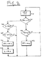
- Figure 2 is a flow diagram of the sequence of operations of the system; this diagram is equally applicable to the Figure 1 circuit and a microcomputer embodiment.
- the sequence is run continuously, starting with block 40.
- the target temperature TT is updated.
- test 44 determines whether the elapsed time t is greater than a predetermined time t0.
- the time t is measured by an internal timer of the microcomputer, and the time t0 corresponds to the period of timer TMR1. If the elapsed time is less than t0, then the heat source HS must be held off regardless of the error temperature TE, and the process returns directly to block 40. If the elapsed time is greater than t0, then the process proceeds to block 45, which determines whether the error temperature TE is greater than the differential Tk. If it is not, then there is still no call for heat, and the process returns to block 40. If TE exceeds Tk, however, then the flag bit FF1 is set to 1, in block 46, turning on the heat source HS. This is followed by block 47, in which the timer is reset to 0. The process then returns to block 40.
- Block 40 can therefore be preceded by a test of a second timer, and block 40 itself bypassed in the second timer has not reached a predetermined value.
- the system may be modified by monitoring TDW directly, and turning the heat source HS off (by resetting flip-flop FF1 or setting the flag bit FF1 to 0) if TDW exceeds a preset limit, which operates as a safety limit.
- the system may also be modified by incorporating also a "minimum off" time in addition to the minimum on time.
- this may be done by adding a second timer, fed from the complementary or reset output of flip-flop FF1, and feeding a second AND gate, via an inverter, connected between the inverter 23 and flip-flop FF1.
- this is represented by adding a test block, like block 44, between blocks 41 and 42.
Landscapes
- Physics & Mathematics (AREA)
- General Physics & Mathematics (AREA)
- Engineering & Computer Science (AREA)
- Automation & Control Theory (AREA)
- Control Of Temperature (AREA)
- Control Of Combustion (AREA)
Applications Claiming Priority (2)
| Application Number | Priority Date | Filing Date | Title |
|---|---|---|---|
| GB848411363A GB8411363D0 (en) | 1984-05-03 | 1984-05-03 | Temperature control system |
| GB8411363 | 1984-05-03 |
Publications (2)
| Publication Number | Publication Date |
|---|---|
| EP0161891A2 true EP0161891A2 (de) | 1985-11-21 |
| EP0161891A3 EP0161891A3 (de) | 1986-01-29 |
Family
ID=10560450
Family Applications (1)
| Application Number | Title | Priority Date | Filing Date |
|---|---|---|---|
| EP85303198A Withdrawn EP0161891A3 (de) | 1984-05-03 | 1985-05-03 | Temperatursteuerungssystem |
Country Status (5)
| Country | Link |
|---|---|
| EP (1) | EP0161891A3 (de) |
| DK (1) | DK199285A (de) |
| FI (1) | FI851750A7 (de) |
| GB (1) | GB8411363D0 (de) |
| NO (1) | NO851751L (de) |
Cited By (2)
| Publication number | Priority date | Publication date | Assignee | Title |
|---|---|---|---|---|
| GB2218542A (en) * | 1988-05-11 | 1989-11-15 | Hogan Andrew Paul | Control of a heating system |
| WO2008012387A1 (es) * | 2006-07-28 | 2008-01-31 | Jvv Grup Montajes Y Desarrollos De Proyectos Electronicos, S.L. | Sistema de calefacción mediante radiadores |
Family Cites Families (4)
| Publication number | Priority date | Publication date | Assignee | Title |
|---|---|---|---|---|
| US4319711A (en) * | 1977-10-11 | 1982-03-16 | Robertshaw Controls Company | Wall thermostat and the like |
| US4485966A (en) * | 1980-12-19 | 1984-12-04 | Cartmell Robert L | Pulsation device for a heating or cooling unit |
| US4470266A (en) * | 1982-03-29 | 1984-09-11 | Carrier Corporation | Timer speedup for servicing an air conditioning unit with an electronic control |
| US4476423A (en) * | 1983-04-20 | 1984-10-09 | Westinghouse Electric Corp. | Motor control apparatus with motor starts per time period limiter |
-
1984
- 1984-05-03 GB GB848411363A patent/GB8411363D0/en active Pending
-
1985
- 1985-05-02 NO NO851751A patent/NO851751L/no unknown
- 1985-05-02 DK DK199285A patent/DK199285A/da not_active Application Discontinuation
- 1985-05-03 FI FI851750A patent/FI851750A7/fi not_active Application Discontinuation
- 1985-05-03 EP EP85303198A patent/EP0161891A3/de not_active Withdrawn
Cited By (6)
| Publication number | Priority date | Publication date | Assignee | Title |
|---|---|---|---|---|
| GB2218542A (en) * | 1988-05-11 | 1989-11-15 | Hogan Andrew Paul | Control of a heating system |
| GB2218542B (en) * | 1988-05-11 | 1992-12-09 | Hogan Andrew Paul | Heating system control |
| WO2008012387A1 (es) * | 2006-07-28 | 2008-01-31 | Jvv Grup Montajes Y Desarrollos De Proyectos Electronicos, S.L. | Sistema de calefacción mediante radiadores |
| ES2289952A1 (es) * | 2006-07-28 | 2008-02-01 | Thierry M. Jvv Grup Montajes Y Desarrollos De Proyectos Electronicos, S.L. | Sistema de calefaccion mediante radiadores. |
| ES2289952B1 (es) * | 2006-07-28 | 2008-12-16 | Thierry M. Jvv Grup Montajes Y Desarrollos De Proyectos Electronicos, S.L. | Sistema de calefaccion mediante radiadores. |
| EP2048565A4 (de) * | 2006-07-28 | 2011-10-19 | Jvv Grup Montajes Y Desarrollos De Proyectos Electronicos S L | Heizstrahlersystem |
Also Published As
| Publication number | Publication date |
|---|---|
| DK199285D0 (da) | 1985-05-02 |
| GB8411363D0 (en) | 1984-06-06 |
| NO851751L (no) | 1985-11-04 |
| EP0161891A3 (de) | 1986-01-29 |
| FI851750L (fi) | 1985-11-04 |
| FI851750A7 (fi) | 1985-11-04 |
| FI851750A0 (fi) | 1985-05-03 |
| DK199285A (da) | 1985-11-04 |
Similar Documents
| Publication | Publication Date | Title |
|---|---|---|
| EP0206165B1 (de) | Uhrenthermostat | |
| EP0309770B1 (de) | Vorrichtung zur Überwachung der Temperatur in einem Kochgerät | |
| EP0049626B1 (de) | Temperaturregelsystem | |
| KR940002642B1 (ko) | 공간 온도의 초과량 혹은 미달량을 제어할 수 있는 온도조절수단 | |
| US4700052A (en) | Apparatus for controlling and adjusting heat output during the heating phase of a steam pressure cooking vessel | |
| DE3113608A1 (de) | Regeleinrichtung | |
| US4759498A (en) | Thermostatic control without temperature droop using duty cycle control | |
| GB1293132A (en) | Improvements in or relating to temperature controllers | |
| EP0298415A2 (de) | Verfahren und Vorrichtung zur thermostatischen Steuerung | |
| US4629852A (en) | Regulator circuit for control of heat output of a heating element | |
| US4489882A (en) | Variable time constant anticipation thermostat | |
| CA1137596A (en) | Expanded time constant condition control system using a unidirectional counter with multiple channels | |
| GB2114828A (en) | Control means for the heating means of a baking oven | |
| US3428250A (en) | Furnace control system | |
| JPS5713526A (en) | Temperature controller | |
| US4506826A (en) | Time-controlled heat regulator with nighttime temperature lowering capability | |
| NO851751L (no) | Temperaturkontrollsystem. | |
| SU1667029A1 (ru) | Устройство дл программного регулировани температуры | |
| GB2161293A (en) | Sequence controller | |
| SU527522A1 (ru) | Устройство дл автоматического регулировани тепловой нагрузки теплофикационной турбоустановки | |
| SU1332261A1 (ru) | Адаптивна система управлени процессом стерилизации | |
| SU779875A1 (ru) | Термостат колонок газового хроматографа | |
| JPS60159553A (ja) | 給湯機の制御装置 | |
| SU1667031A1 (ru) | Термоэлектрическа система регулировани температуры | |
| SU1640679A1 (ru) | Устройство дл регулировани температуры |
Legal Events
| Date | Code | Title | Description |
|---|---|---|---|
| PUAI | Public reference made under article 153(3) epc to a published international application that has entered the european phase |
Free format text: ORIGINAL CODE: 0009012 |
|
| AK | Designated contracting states |
Designated state(s): BE FR GB SE |
|
| PUAL | Search report despatched |
Free format text: ORIGINAL CODE: 0009013 |
|
| AK | Designated contracting states |
Designated state(s): BE FR GB SE |
|
| 17P | Request for examination filed |
Effective date: 19860820 |
|
| 17Q | First examination report despatched |
Effective date: 19880624 |
|
| STAA | Information on the status of an ep patent application or granted ep patent |
Free format text: STATUS: THE APPLICATION IS DEEMED TO BE WITHDRAWN |
|
| 18D | Application deemed to be withdrawn |
Effective date: 19881105 |
|
| RIN1 | Information on inventor provided before grant (corrected) |
Inventor name: HUGHES, DAVID GARETH Inventor name: MCGINLEY, CHARLES EDWARD |