EP0161897A2 - Scie sauteuse à lame orientable - Google Patents
Scie sauteuse à lame orientable Download PDFInfo
- Publication number
- EP0161897A2 EP0161897A2 EP85303215A EP85303215A EP0161897A2 EP 0161897 A2 EP0161897 A2 EP 0161897A2 EP 85303215 A EP85303215 A EP 85303215A EP 85303215 A EP85303215 A EP 85303215A EP 0161897 A2 EP0161897 A2 EP 0161897A2
- Authority
- EP
- European Patent Office
- Prior art keywords
- scroller
- locking
- lever
- scrolling
- drive shaft
- Prior art date
- Legal status (The legal status is an assumption and is not a legal conclusion. Google has not performed a legal analysis and makes no representation as to the accuracy of the status listed.)
- Granted
Links
- 230000006835 compression Effects 0.000 claims description 3
- 238000007906 compression Methods 0.000 claims description 3
- 241000763859 Dyckia brevifolia Species 0.000 description 25
- 230000007246 mechanism Effects 0.000 description 6
- 238000010276 construction Methods 0.000 description 3
- 230000002093 peripheral effect Effects 0.000 description 2
- 239000007787 solid Substances 0.000 description 2
- 230000004048 modification Effects 0.000 description 1
- 238000012986 modification Methods 0.000 description 1
Images


Classifications
-
- B—PERFORMING OPERATIONS; TRANSPORTING
- B23—MACHINE TOOLS; METAL-WORKING NOT OTHERWISE PROVIDED FOR
- B23D—PLANING; SLOTTING; SHEARING; BROACHING; SAWING; FILING; SCRAPING; LIKE OPERATIONS FOR WORKING METAL BY REMOVING MATERIAL, NOT OTHERWISE PROVIDED FOR
- B23D49/00—Machines or devices for sawing with straight reciprocating saw blades, e.g. hacksaws
- B23D49/10—Hand-held or hand-operated sawing devices with straight saw blades
- B23D49/16—Hand-held or hand-operated sawing devices with straight saw blades actuated by electric or magnetic power or prime movers
- B23D49/162—Pad sawing devices
- B23D49/167—Pad sawing devices with means to adjust the guide plate or with means to adjust the plane in which the saw blade moves
-
- Y—GENERAL TAGGING OF NEW TECHNOLOGICAL DEVELOPMENTS; GENERAL TAGGING OF CROSS-SECTIONAL TECHNOLOGIES SPANNING OVER SEVERAL SECTIONS OF THE IPC; TECHNICAL SUBJECTS COVERED BY FORMER USPC CROSS-REFERENCE ART COLLECTIONS [XRACs] AND DIGESTS
- Y10—TECHNICAL SUBJECTS COVERED BY FORMER USPC
- Y10T—TECHNICAL SUBJECTS COVERED BY FORMER US CLASSIFICATION
- Y10T83/00—Cutting
- Y10T83/687—By tool reciprocable along elongated edge
- Y10T83/6875—With means permitting tool to be rotatably adjusted about its cutting edge during cutting
Definitions
- This invention relates to jig saws and more particularly scroller jig saws, namely jig saws in which the reciprocating saw-blade may be rotated about the axis of reciprocation of the saw blade.
- a scroller jig saw it is desirable for a scroller jig saw to be able to operate in both a scrolling and a non-scrolling mode.
- the operator In the scrolling mode the operator needs to be able to control rotation of the saw blade about its longitudinal axis, while in the non-scrolling mode the saw blade needs to be locked against such rotation.
- the saw blade can be locked in the conventional position, namely with the cutting edge of the saw blade facing directly forwards, but it is also desirable that the saw blade should be lockable in other angular positions.
- a feature by which this object is achieved is the provision of a pivoted lever which is spring biased to lock rotation of the saw blade in a non-scrolling position of a locking control member and to pivot the lever to an inoperative position in a scrolling position of the control member.
- a scroller jig saw having a housing, a saw blade drive shaft mounted for reciprocating movement relative to the housing along a longitudinal axis and for rotation about said axis, a motor drivingly connected to said drive shaft for reciprocating said drive shaft along said axis, a scrolling control member accessible to an operator and coupled to said drive shaft for rotation thereof, locking means for releasably locking said drive shaft against rotation, said locking means comprising a pivotally mounted lever pivotal between a locking position in which said drive shaft is locked against rotation and a free position in which said drive shaft is free to rotate, said lever being resiliently biased towards said locking position, and a locking control member accessible to the operator and movable between a scrolling position in which said lever is held in said free position and a - non-scrolling position in which said lever is free to be biased into said locking position.
- the locking control member preferably comprises a rotatable cam member mounted for rotation about the axis of the saw blade drive shaft and including a cam surface engageable with the locking lever.
- the locking control member may advantageously include at least one lug projecting through the housing.
- the lug preferably projects through a side of the housing adjacent the scrolling control member.
- the saw blade drive shaft may be mounted in a scrolling control assembly, including the scrolling control member, for reciprocation relative thereto but rotatably coupled thereto.
- the scrolling control assembly may be mounted for rotation about the axis of the saw blade drive shaft.
- the locking control member is preferably mounted on the scrolling control assembly.
- the locking lever is pivotally mounted intermediate its ends, is resiliently biased by a compression spring at one end, is engageable with the locking control member at the other end, and is engageable with a member rotatably coupled to the saw blade drive shaft between the other end and the pivotal mounting of the locking lever.
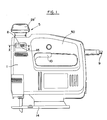
- the scroller jig saw shown in the drawings includes a housing 1 of clam shell construction on the bottom of which a shoe 14 is mounted.
- the housing 1 is formed with a handle 50.
- Received in the housing 1 are, inter alia, an electric motor 2, a saw blade drive shaft 3 arranged to be reciprocated by the motor as will be described in more detail later, a scrolling control assembly including a control block 4 and a control knob 5 projecting externally of the casing, and a releasable locking means for locking the scrolling control assembly.
- the releasable locking means consists of a spring biased locking lever 6, and a cam 7 rotatably mounted on the scrolling control assembly and accessible to an operator by virtue of openings 8 on opposite sides of the housing 1 below but adjacent the knob 5.
- the motor 2 has an armature shaft which carries a pinion 11 on its end, the pinion 11 meshing with a gear 12 fixed to a rotatably mounted spindle 13.
- the gear 12 carries an eccentric pin 15 which is slideably mounted in a horizontal track of a yoke 16 having a central bore in which the saw blade drive shaft 3, which is of circular cross-section, is received. Longitudinal relative movement of the shaft 3 relative to the yoke 16 is prevented by pins 17 which pass through the shaft 3 and project therefrom on either side of the yoke 16.
- the shaft 3 is mounted for reciprocating and rotational movement in upper and lower space apart bearings 18, 19, and its lower end carries a saw blade holder 20 in which a saw blade 21 is mounted and replaceably secured therein. Adjacent the top end of the shaft 3 a transverse pin 22 passes through the shaft and projects a short distance out of the shaft on each side. The upper end of the shaft 3 is slidably received in a non-circular bore of the control block 4.
- control block 4 has a bore with a central circular portion 24 and diametrically opposite extensions 25 in which the ends of the pin 22 are received.
- shaft 3 is able to reciprocate longitudinally relative to the block 4 but is locked against rotation relative to the block.
- the block 4 carries a peripheral flange 26 at its upper end and this flange is provided with four apertures 27 equispaced around the flange and also with four notches 40 in its periphery equispaced between the apertures 27.
- the Manually graspable control knob 5 is formed in two parts, namely a lower main part 28, which extends downwardly through the top of the housing 1, and an upper cap part 29 which is snap fitted onto the part 28.
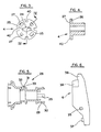
- the lower part 28 is shown in Fig. 5 and at its bottom end carrie four legs 29 which extend downwardly parallel to the axis of rotation of the drive shaft 3 and which snap fit into the apertures 27 in the block 4.
- the legs 29 carry feet 30 which project on the lower side of the flange 26 and retain the control knob on the control block (see Fig. 2).
- the bearing portion 31 mounts the control knob 5 in a correspondingly sized opening 51 in the top of the housing 1 for rotation about its longitudinal axis, which is also the longitudinal axis of the shaft 3.
- the locking lever 6, shown in Figs. 2 and 6 is pivotally mounted on a pivot 35 and is biased by a compression spring 36 compressed between the lower end of the lever 6 and an internal part of the housing 1 in which the upper bearing 18 is supported.
- a boss 37 (see Fig. 6) formed on the lower end of the lever 6 locates the spring relative to the lever.
- the lever 6 At its top end the lever 6 has a curved nose 38 which is engageable with the cam 7 as will be described below.
- a latch part 39 Immediately below the nose 38 is a latch part 39, and the cross-section of this part is arranged to match the cross-section of each of the notches 40 in the flange 26 so that the latch part 39 is selectively engageable with each of the notches-.
- the lever 6 is shown in solid outline in the locking position to which it is biased by the spring 36; in this locking position the latch part 39 is engaged with a selected notch 40 on the control block 4.
- the ring-shaped cam 7 shown in Figs. 7 to 9 has a central bore 41 through which the lower part 28 of the control knobs extends and which receives the upper parts of the legs 29.
- the cam 7 is thus rotatably mounted on the scroller control assembly.
- a pair of radially extending serrated lugs 45 are formed on diametrically opposite parts of the cam 7 and extend through the openings 8 in the housing 1.
- the peripheral surface of the cam 7 is shaped to define a raised face 42, a recessed face 43 and an interconnecting sloping face 44, these parts. together defining a cam surface.
- a resilient tongue 46 Formed in the top surface of the cam 7 at the location of each of the lugs 45 is a resilient tongue 46, disconnected from the rest of the cam 7 on three sides by a slot 47, and carrying a pip 48 protruding above the general top surface of the cam.
- an upper wall 49 is provided with a pair of recesses 50 formed therein.
- the cam 7 is so positioned relative to the housing 1 that the general surface of the top of the cam 7 is immediately adjacent the wall 49 and, with the lug 45 projecting centrally through the respective opening 8, the pip 48 is pressed downwardly into the body of the cam.
- the pip 49 moves into a recess 50 so releasably securing the cam 7 in either a scrolling or non-scrolling position. Substantial movement of the cam further to one side is prevented by engagement of the lugs 45 with the sides of the openings 8.
- the two positions of the cam 7 in which the pips 48 are received in the recesses 50 define the two working positions of the can and it will be appreciated that the can "clicks" into both these positions. In one of these positions (the non-scrolling position) which is shown in Fig.
- the recessed face 43 of the cam 7 is aligned with the nose 38 of the locking lever 6 and the locking lever is free to be spring biased into the locking position shown in solid outline in Fig. 2.
- the cam 7 is rotated to the other position (the scrolling position)
- the nose 38 comes into camming engagement first with the sloping face 44 of the cam and then with the raised face 42 and the locking lever 6 is moved to the 'Tree position" shown in dotted outline in Fig. 2, in which the latch part 39 of the lever is disengaged and spaced from the control block 4 and the scrolling control assembly 4, 5 is therefore able to rotate.
- the saw operates as follows.
- the pinion 11 is driven by the motor 2 and in turn rotates the gear 12.
- Rotation of the gear 12 causes orbital movement of the pin 15; the horizontal component of this orbital movement is accommodated by the pin sliding in the yoke 16 while the vertical component is translated into reciprocating movement of the shaft 3 in the bearings 18, 19 and reciprocating movement of the saw blade 21.
- the saw blade is rotatably mounted via its drive shaft 3 in the bearings 18, 19,it is rotatably locked relative to the control block 4 and this in turn is locked against rotation by the engagement of the latch part 39 of the lever 6 in one of the notches 40 of the control block 4.
- the saw blade 21 is locked in the angular position shown in Fig. 2 and will not rotate even if a user attempts to rotate the control knob 5 (which is now also locked against rotation). In this non-scrolling mode the saw operates as a conventional jig saw.
- the latch part 39 of the lever 6 will be biased into contact with the periphery of the control block 4, and the saw will remain in the scrolling mode until the scroller control assembly is rotated sufficiently to bring one of the notches 40 into approximate alignment with the lever 6. It will be appreciated that the four notches 40 on the control block 4 provide four orientations, spaced 90° apart from one another, in which the saw blade can be locked.
Landscapes
- Engineering & Computer Science (AREA)
- Mechanical Engineering (AREA)
- Sawing (AREA)
Applications Claiming Priority (2)
| Application Number | Priority Date | Filing Date | Title |
|---|---|---|---|
| GB8412057A GB2158393B (en) | 1984-05-11 | 1984-05-11 | Scroller jig saw |
| GB8412057 | 1984-05-11 |
Publications (3)
| Publication Number | Publication Date |
|---|---|
| EP0161897A2 true EP0161897A2 (fr) | 1985-11-21 |
| EP0161897A3 EP0161897A3 (en) | 1986-08-13 |
| EP0161897B1 EP0161897B1 (fr) | 1988-09-21 |
Family
ID=10560801
Family Applications (1)
| Application Number | Title | Priority Date | Filing Date |
|---|---|---|---|
| EP19850303215 Expired EP0161897B1 (fr) | 1984-05-11 | 1985-05-07 | Scie sauteuse à lame orientable |
Country Status (4)
| Country | Link |
|---|---|
| US (1) | US4693009A (fr) |
| EP (1) | EP0161897B1 (fr) |
| DE (1) | DE3565060D1 (fr) |
| GB (1) | GB2158393B (fr) |
Families Citing this family (42)
| Publication number | Priority date | Publication date | Assignee | Title |
|---|---|---|---|---|
| GB2174642A (en) * | 1985-05-07 | 1986-11-12 | Black & Decker Inc | Jig saw |
| USD297208S (en) | 1985-08-08 | 1988-08-16 | Black & Decker, Inc. | Scroller jig saw |
| DE4001996A1 (de) * | 1990-01-24 | 1991-07-25 | Scintilla Ag | Pendelhubsaege |
| USD332902S (en) | 1990-07-30 | 1993-02-02 | Ryobi Motor Products Corp. | Sabre saw |
| US5421232A (en) * | 1992-09-26 | 1995-06-06 | Black & Decker Inc. | Reciprocating saw |
| US5618129A (en) * | 1995-03-13 | 1997-04-08 | Paragon Electric Company, Inc. | Snap-engaging mounting plate |
| US5561909A (en) * | 1995-06-26 | 1996-10-08 | Berg; Donald N. E. | Battery operated saw |
| US6230411B1 (en) * | 1998-07-10 | 2001-05-15 | Porter-Cable Corporation | Blade guide system for a jigsaw |
| US6094826A (en) * | 1998-09-01 | 2000-08-01 | Hobbico, Inc. | Reciprocating slot cutting tool |
| US6568089B1 (en) * | 1999-06-04 | 2003-05-27 | Porter-Cable/Delta | Reciprocating saw having compact configuration and independent stability |
| GB2380159A (en) * | 2001-09-29 | 2003-04-02 | Black & Decker Inc | Power tool |
| US6671969B2 (en) | 2001-12-18 | 2004-01-06 | Porter-Cable/Delta | Adjustable shoe for a reciprocating saw |
| US20070006468A1 (en) | 2005-07-06 | 2007-01-11 | Christopher Davies | Cutting device |
| RS51409B (sr) * | 2002-07-25 | 2011-02-28 | Belron Hungary Kft- Zug Branch | Rezni alat i postupak za izrezivanje vetrobranskih stakala motornih vozila |
| US20040148789A1 (en) * | 2002-08-20 | 2004-08-05 | Gist Leslie D. | Rotatable handle for reciprocating saws |
| USD476871S1 (en) | 2002-11-02 | 2003-07-08 | S-B Power Tool Corporation | Jigsaw |
| US7065884B2 (en) | 2003-02-28 | 2006-06-27 | Credo Technology Corporation | Power hand tool foot assembly |
| GB2399314B (en) * | 2003-03-13 | 2005-02-23 | Black & Decker Inc | Power tool having rotatable adjustment means for working member |
| USD486711S1 (en) | 2003-03-27 | 2004-02-17 | Credo Technology Corporation | Jigsaw with vacuum port |
| USD483637S1 (en) | 2003-03-27 | 2003-12-16 | Credo Technology Corporation | Jigsaw with vacuum port |
| US7234243B2 (en) * | 2003-06-25 | 2007-06-26 | Credo Technology Corporation | Reciprocating cutting tool with orbital action |
| AU157250S (en) * | 2003-07-28 | 2005-01-12 | Positec Power Tools Suzhou Co Ltd | Jigsaw |
| CA106159S (en) * | 2003-09-10 | 2005-06-07 | Chervon Internat Trading Co Ltd | Jig saw |
| AU156978S (en) * | 2003-09-15 | 2004-12-02 | Chervon Int Trading Co Ltd | Jig saw |
| US20070180711A1 (en) * | 2003-09-19 | 2007-08-09 | Keith Park | Jigsaw actuation mechanism for imparting scrolling, orbital and reciprocating movement |
| US7526867B2 (en) * | 2003-09-19 | 2009-05-05 | Gmca Pty Limited | Tool with clamping apparatus and an improved scrolling mechanism |
| US20050132582A1 (en) * | 2003-12-17 | 2005-06-23 | Peter Gudmundson | Jigsaws |
| AU301222S (en) * | 2004-05-14 | 2005-03-31 | Black & Decker Inc | A jigsaw |
| DE602004002572T2 (de) * | 2004-05-18 | 2007-07-12 | Black & Decker Inc., Newark | Anordnung eines Ausgangsstössels und motorisiertes Werkzeug mit einer solchen Anordnung |
| EP1598134B1 (fr) * | 2004-05-18 | 2008-04-09 | BLACK & DECKER INC. | Outil motorisé comprenant un mécanisme de sélection de mode de fonctionnement |
| USD523311S1 (en) * | 2004-09-17 | 2006-06-20 | Black & Decker Inc. | Jigsaw |
| US20060288592A1 (en) * | 2005-06-24 | 2006-12-28 | Nigel Roberts | Reciprocating tool |
| US8033026B2 (en) | 2007-09-21 | 2011-10-11 | Black & Decker Inc. | Adjustable and removable keel assembly and blade guide for a jigsaw |
| US9827623B2 (en) | 2007-09-21 | 2017-11-28 | Black & Decker Inc. | Control of reciprocation speed and orbital magnitude of a jigsaw with a plurality of material and/or task descriptive icons |
| US10029322B2 (en) | 2007-09-21 | 2018-07-24 | Black & Decker Inc. | Housing of a cutting tool including blade storage, integral blade guard and motor ventilation pathway |
| US9981327B2 (en) | 2007-09-21 | 2018-05-29 | Black & Decker Inc. | Cutting angle indicator in jigsaw housing with dust extraction |
| CN201295796Y (zh) * | 2008-03-28 | 2009-08-26 | 南京德朔实业有限公司 | 一种往复锯 |
| US8230607B2 (en) * | 2008-05-09 | 2012-07-31 | Milwaukee Electric Tool Corporation | Keyless blade clamp for a power tool |
| US8205342B2 (en) | 2008-12-23 | 2012-06-26 | Credo Technology Corporation | Rotating spindle for a reciprocating saw |
| US8578615B2 (en) | 2011-09-12 | 2013-11-12 | Black & Decker Inc. | Jigsaw with deployable keel and tiltable shoe |
| US9559628B2 (en) | 2013-10-25 | 2017-01-31 | Black & Decker Inc. | Handheld power tool with compact AC switch |
| US10335874B2 (en) * | 2014-05-23 | 2019-07-02 | Koki Holdings Co., Ltd. | Reciprocating tool |
Family Cites Families (11)
| Publication number | Priority date | Publication date | Assignee | Title |
|---|---|---|---|---|
| US3494390A (en) * | 1968-03-18 | 1970-02-10 | Singer Co | Sabre saws with 360 degree swivel saw bar |
| US3542097A (en) * | 1968-05-02 | 1970-11-24 | Singer Co | Chuck assembly for sabre saws |
| US3547166A (en) * | 1968-07-03 | 1970-12-15 | Singer Co | Chuck attachment for sabre saws |
| US3665983A (en) * | 1970-12-15 | 1972-05-30 | Singer Co | Sabre saws with angularly adjustable swivel saw bars |
| US3729822A (en) * | 1972-03-09 | 1973-05-01 | Singer Co | Sabre saws with lockable swivel saw bars |
| US3795980A (en) * | 1972-11-29 | 1974-03-12 | Singer Co | Chuck device for sabre saws |
| DE7513910U (de) * | 1975-04-30 | 1976-11-04 | Scintilla Ag, Solothurn (Schweiz) | Zusatzgriff, insbesondere fuer kraftwerkzeuge |
| US4240204A (en) * | 1979-06-19 | 1980-12-23 | Black & Decker Inc. | Jig saw |
| US4283855A (en) * | 1980-04-07 | 1981-08-18 | The Singer Company | Sabre saw with rotatable saw bar |
| CA1211685A (fr) * | 1983-02-07 | 1986-09-23 | James R. Hartmann | Scie alternative reglable avec mecanisme de commande orbital |
| US4545123A (en) * | 1984-04-09 | 1985-10-08 | Skil Corporation | Combination jig saw adjusting mechanism |
-
1984
- 1984-05-11 GB GB8412057A patent/GB2158393B/en not_active Expired
-
1985
- 1985-05-07 EP EP19850303215 patent/EP0161897B1/fr not_active Expired
- 1985-05-07 DE DE8585303215T patent/DE3565060D1/de not_active Expired
- 1985-05-09 US US06/732,419 patent/US4693009A/en not_active Expired - Lifetime
Also Published As
| Publication number | Publication date |
|---|---|
| EP0161897A3 (en) | 1986-08-13 |
| US4693009A (en) | 1987-09-15 |
| GB2158393B (en) | 1987-05-20 |
| EP0161897B1 (fr) | 1988-09-21 |
| GB8412057D0 (en) | 1984-06-20 |
| GB2158393A (en) | 1985-11-13 |
| DE3565060D1 (en) | 1988-10-27 |
Similar Documents
| Publication | Publication Date | Title |
|---|---|---|
| EP0161897B1 (fr) | Scie sauteuse à lame orientable | |
| EP0125101B1 (fr) | Scie orbitale | |
| CA1229288A (fr) | Mecanisme de reglage pour scie a decouper combinee | |
| JP3080975B2 (ja) | 電気バリカン | |
| EP2943316B1 (fr) | Outil doté d'une tête rotative | |
| US3873796A (en) | Trigger mechanism for hand-operated power device including independently operable locking devices providing automatic lock off and manual lock-on operation | |
| US8827004B2 (en) | Power tool having off-lock member | |
| US20040148789A1 (en) | Rotatable handle for reciprocating saws | |
| US7526867B2 (en) | Tool with clamping apparatus and an improved scrolling mechanism | |
| JP2002192419A (ja) | 往復動鋸用ハンドル構造 | |
| US11897044B2 (en) | Cutting machine | |
| WO2003028966A2 (fr) | Outils electriques et lames associees utilisees avec lesdits outils | |
| EP1736267A1 (fr) | Outil à mouvement alternatif | |
| US6489578B1 (en) | Electrical switch | |
| JPH0752067A (ja) | 電池式刃物工具 | |
| CN222113696U (zh) | 一种手持式电动工具 | |
| CN222903535U (zh) | 角磨机 | |
| US11872646B2 (en) | Reciprocating tool | |
| JPH0732990B2 (ja) | 電池式電動工具 | |
| JP2006326780A (ja) | 刃物付き電動工具 | |
| JPS58122030A (ja) | ミキサ−の安全装置 | |
| JPH0123408Y2 (fr) | ||
| JPH0724228Y2 (ja) | 食肉スライサの操作スイッチ | |
| JP2024120301A (ja) | 電動工具 | |
| JPH0228003Y2 (fr) |
Legal Events
| Date | Code | Title | Description |
|---|---|---|---|
| PUAI | Public reference made under article 153(3) epc to a published international application that has entered the european phase |
Free format text: ORIGINAL CODE: 0009012 |
|
| AK | Designated contracting states |
Designated state(s): BE DE FR IT |
|
| PUAL | Search report despatched |
Free format text: ORIGINAL CODE: 0009013 |
|
| AK | Designated contracting states |
Kind code of ref document: A3 Designated state(s): BE DE FR IT |
|
| 17P | Request for examination filed |
Effective date: 19860814 |
|
| 17Q | First examination report despatched |
Effective date: 19880122 |
|
| GRAA | (expected) grant |
Free format text: ORIGINAL CODE: 0009210 |
|
| AK | Designated contracting states |
Kind code of ref document: B1 Designated state(s): BE DE FR IT |
|
| PG25 | Lapsed in a contracting state [announced via postgrant information from national office to epo] |
Ref country code: IT Free format text: LAPSE BECAUSE OF FAILURE TO SUBMIT A TRANSLATION OF THE DESCRIPTION OR TO PAY THE FEE WITHIN THE PRESCRIBED TIME-LIMIT;WARNING: LAPSES OF ITALIAN PATENTS WITH EFFECTIVE DATE BEFORE 2007 MAY HAVE OCCURRED AT ANY TIME BEFORE 2007. THE CORRECT EFFECTIVE DATE MAY BE DIFFERENT FROM THE ONE RECORDED. Effective date: 19880921 Ref country code: BE Effective date: 19880921 |
|
| REF | Corresponds to: |
Ref document number: 3565060 Country of ref document: DE Date of ref document: 19881027 |
|
| ET | Fr: translation filed | ||
| PLBE | No opposition filed within time limit |
Free format text: ORIGINAL CODE: 0009261 |
|
| STAA | Information on the status of an ep patent application or granted ep patent |
Free format text: STATUS: NO OPPOSITION FILED WITHIN TIME LIMIT |
|
| 26N | No opposition filed | ||
| PGFP | Annual fee paid to national office [announced via postgrant information from national office to epo] |
Ref country code: FR Payment date: 20030520 Year of fee payment: 19 |
|
| PGFP | Annual fee paid to national office [announced via postgrant information from national office to epo] |
Ref country code: DE Payment date: 20030626 Year of fee payment: 19 |
|
| PG25 | Lapsed in a contracting state [announced via postgrant information from national office to epo] |
Ref country code: DE Free format text: LAPSE BECAUSE OF NON-PAYMENT OF DUE FEES Effective date: 20041201 |
|
| PG25 | Lapsed in a contracting state [announced via postgrant information from national office to epo] |
Ref country code: FR Free format text: LAPSE BECAUSE OF NON-PAYMENT OF DUE FEES Effective date: 20050131 |
|
| REG | Reference to a national code |
Ref country code: FR Ref legal event code: ST |