EP0161945A1 - Fernschalthilfseinheit eines elektrischen Schutzschalters - Google Patents
Fernschalthilfseinheit eines elektrischen Schutzschalters Download PDFInfo
- Publication number
- EP0161945A1 EP0161945A1 EP85400142A EP85400142A EP0161945A1 EP 0161945 A1 EP0161945 A1 EP 0161945A1 EP 85400142 A EP85400142 A EP 85400142A EP 85400142 A EP85400142 A EP 85400142A EP 0161945 A1 EP0161945 A1 EP 0161945A1
- Authority
- EP
- European Patent Office
- Prior art keywords
- circuit breaker
- remote
- drum
- movable core
- closing
- Prior art date
- Legal status (The legal status is an assumption and is not a legal conclusion. Google has not performed a legal analysis and makes no representation as to the accuracy of the status listed.)
- Granted
Links
- 230000005540 biological transmission Effects 0.000 claims abstract description 14
- 230000007246 mechanism Effects 0.000 claims abstract description 13
- 230000009466 transformation Effects 0.000 claims abstract description 4
- 230000000903 blocking effect Effects 0.000 claims description 3
- 230000008878 coupling Effects 0.000 claims description 3
- 238000010168 coupling process Methods 0.000 claims description 3
- 238000005859 coupling reaction Methods 0.000 claims description 3
- 230000009471 action Effects 0.000 description 2
- 230000005284 excitation Effects 0.000 description 2
- 238000004519 manufacturing process Methods 0.000 description 2
- 241001417494 Sciaenidae Species 0.000 description 1
- 230000006835 compression Effects 0.000 description 1
- 238000007906 compression Methods 0.000 description 1
- 230000000994 depressogenic effect Effects 0.000 description 1
- 238000006073 displacement reaction Methods 0.000 description 1
- 230000005294 ferromagnetic effect Effects 0.000 description 1
- 230000005291 magnetic effect Effects 0.000 description 1
- 238000000034 method Methods 0.000 description 1
- 230000005405 multipole Effects 0.000 description 1
Images

Classifications
-
- H—ELECTRICITY
- H01—ELECTRIC ELEMENTS
- H01H—ELECTRIC SWITCHES; RELAYS; SELECTORS; EMERGENCY PROTECTIVE DEVICES
- H01H3/00—Mechanisms for operating contacts
- H01H3/32—Driving mechanisms, i.e. for transmitting driving force to the contacts
- H01H3/36—Driving mechanisms, i.e. for transmitting driving force to the contacts using belt, chain, or cord
-
- H—ELECTRICITY
- H01—ELECTRIC ELEMENTS
- H01H—ELECTRIC SWITCHES; RELAYS; SELECTORS; EMERGENCY PROTECTIVE DEVICES
- H01H89/00—Combinations of two or more different basic types of electric switches, relays, selectors and emergency protective devices, not covered by any single one of the other main groups of this subclass
- H01H89/06—Combination of a manual reset circuit with a contactor, i.e. the same circuit controlled by both a protective and a remote control device
- H01H89/08—Combination of a manual reset circuit with a contactor, i.e. the same circuit controlled by both a protective and a remote control device with both devices using the same contact pair
-
- H—ELECTRICITY
- H01—ELECTRIC ELEMENTS
- H01H—ELECTRIC SWITCHES; RELAYS; SELECTORS; EMERGENCY PROTECTIVE DEVICES
- H01H71/00—Details of the protective switches or relays covered by groups H01H73/00 - H01H83/00
- H01H71/02—Housings; Casings; Bases; Mountings
- H01H71/0264—Mountings or coverplates for complete assembled circuit breakers, e.g. snap mounting in panel
- H01H71/0271—Mounting several complete assembled circuit breakers together
-
- H—ELECTRICITY
- H01—ELECTRIC ELEMENTS
- H01H—ELECTRIC SWITCHES; RELAYS; SELECTORS; EMERGENCY PROTECTIVE DEVICES
- H01H71/00—Details of the protective switches or relays covered by groups H01H73/00 - H01H83/00
- H01H71/10—Operating or release mechanisms
- H01H71/1009—Interconnected mechanisms
-
- H—ELECTRICITY
- H01—ELECTRIC ELEMENTS
- H01H—ELECTRIC SWITCHES; RELAYS; SELECTORS; EMERGENCY PROTECTIVE DEVICES
- H01H71/00—Details of the protective switches or relays covered by groups H01H73/00 - H01H83/00
- H01H71/10—Operating or release mechanisms
- H01H71/1009—Interconnected mechanisms
- H01H71/1018—Interconnected mechanisms with only external interconnections
-
- H—ELECTRICITY
- H01—ELECTRIC ELEMENTS
- H01H—ELECTRIC SWITCHES; RELAYS; SELECTORS; EMERGENCY PROTECTIVE DEVICES
- H01H71/00—Details of the protective switches or relays covered by groups H01H73/00 - H01H83/00
- H01H71/10—Operating or release mechanisms
- H01H71/66—Power reset mechanisms
- H01H71/68—Power reset mechanisms actuated by electromagnet
-
- H—ELECTRICITY
- H01—ELECTRIC ELEMENTS
- H01H—ELECTRIC SWITCHES; RELAYS; SELECTORS; EMERGENCY PROTECTIVE DEVICES
- H01H9/00—Details of switching devices, not covered by groups H01H1/00 - H01H7/00
- H01H9/20—Interlocking, locking, or latching mechanisms
- H01H9/28—Interlocking, locking, or latching mechanisms for locking switch parts by a key or equivalent removable member
- H01H9/281—Interlocking, locking, or latching mechanisms for locking switch parts by a key or equivalent removable member making use of a padlock
- H01H9/282—Interlocking, locking, or latching mechanisms for locking switch parts by a key or equivalent removable member making use of a padlock and a separate part mounted or mountable on the switch assembly and movable between an unlocking position and a locking position where it can be secured by the padlock
Definitions
- the object of the present invention is to improve the embodiment of the closing stage of the auxiliary remote control unit of the circuit breaker.
- the remote-controlled circuit breaker according to the invention is characterized in that the said kinematic chain comprises a transmission system by cable or belt, coupled between the movable core and a driving drum of the lever towards the stable closing position of the circuit breaker during the excitation of the control coil of the closing electromagnet, and that the drum cooperates with an elastic means of reminder to return the movable core to the separated position after de-energizing of said coil.
- the drum is pivotally mounted on a fixed axis extending orthogonally to the direction of movement of the movable core.
- the intermediate part of the transmission system cable passes over a return roller which is part of a tensioner.
- An adjustment screw makes it possible to adjust the relative position of the tensioner with respect to the movable core and the drum.
- the elastic return means comprises a torsion spring threaded on the axis of the drum to urge the latter towards an inactive position allowing local manual control of the handle of the circuit breaker.
- the main circuit breaker block has a multipole structure comprising a stack of poles, the handles of which are mechanically coupled together by means of a common bar.
- the latter is advantageously secured to an intermediate lever which reproduces at all times the exact position of the levers.
- the lever is pivotally mounted on the axis of the drum, the latter being arranged to unidirectionally drive the intermediate lever in the direction closing when the coil is energized, and to return to the inactive position after de-energizing the coil.
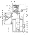
- an auxiliary electrical remote control unit 10 is attached by snap-fastening to a side face of a main circuit breaker main unit 12 standard to form a remote-controlled three-pole circuit breaker with molded case intended to ensure the opening-closing command from a distance and the protection '' a low voltage distribution circuit.
- each pole R, S, T of the circuit breaker block 12 which can be of the type described in French patent N ° 2,350,680.
- Each pole R, S, T comprises a pair of connection terminals 14, 16, separable contacts (not shown) and an actuation mechanism (not shown) of the movable contact between the open and closed positions.
- the mechanism cooperates with a manual control lever 18 with two stable positions, and with the thermomagnetic trip device for automatic triggering in the event of an overload or short-circuit.
- the levers 18 of the different poles R, S, T of the circuit breaker block 12 are mechanically coupled together by means of a common bar 20, described for example in French patents Nos. 2,494,031 and 2,414,784.
- the remote opening-closing command function is performed by the remote control unit 10 equipped with one or two terminal blocks 22 for external connection.
- the outline of the housing 21 of the remote control unit 10 corresponds to that of the circuit breaker unit 12 to form, after assembly, a one-piece assembly.
- the assembly of the two modular housings of the blocks 10, 12 takes place by means of a latching device described in French patent No. 2,411,329.
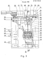
- the side face 24 (fig. 3) of the housing 21 of the remote control unit 10 has a latching element 26 of the latching device, centering pins 28 which fit into conjugated housings of the housing of the pole T in position adjoining the blocks 10, 12Jet means 30, 32 for transmitting the tripping movement between the two blocks 10, 12.
- the transmission means 30, 32 form first and second mechanical control links between the mechanism of the circuit breaker block 12 and the opening stage of the remote control unit 10. The opening stage of the latter does not form part of the invention and will not be described below.
- the closing stage of the remote control unit 10 comprises a closing electromagnet 34 (FIGS. 2 and 3) with a control coil 36 surrounded by a ferromagnetic yoke 38.
- the tubular coil 36 is mounted coaxially on an insulating sheath 40 inside which is arranged a movable sliding core 42 cooperating by magnetic attraction with a fixed core 44 secured to the yoke 38.
- the electromagnet 34 rests on the bottom of the housing 21, and the active end 45 of the movable core 42 is connected to the bar 20 for coupling the levers 18 of the circuit breaker block 12 by means of a transmission system 46 by flexible cable 48.
- the transmission system 46 includes a connection unidirectional drum drag 50 provided with an extension 51 acting on an arm of an intermediate lever 52 secured to the bar 20.
- the drum 50 and the intermediate lever 52 are pivotally mounted on a fixed axis 54 arranged in the upper part of the housing 21 extending parallel to the bar 20 and orthogonally to the direction of movement of the mobile core 42.
- the cable 48 is provided with an end piece 56 anchored in a yoke 58 pivoting on an axis 60 auxiliary to the drum 50.
- the part intermediate of the cable 48 passes over a deflection roller 62 mounted for rotation on an axis 66 of a caliper 64.
- the roller 62 and caliper assembly constitutes a tensioner 65 whose position is adjustable by means of an adjustment screw 68 .
- An elastic return means biases the drum 50 clockwise in abutment against a stop formed by the wall of the housing 21.
- the elastic means comprises a torsion spring 70 threaded on the axis 54, one of the ends of the spring 70 being anchored to the drum 50 and the opposite end bearing on a boss 72 of the housing 21.
- the return of the drum 50 to the inactive position takes place automatically after the coil 36 of the closing electromagnet 34 has de-energized and simultaneously causes the movable core 42 to return to the separated position thanks to the cable connection 48.
- the arrangement of the transmission system 46 does not require any auxiliary return spring between the fixed 44 and mobile 42 cores of the electromagnet 34.
- the intermediate lever 52 follows the bar 20 during the opening and closing movement of the circuit breaker, and reproduces at all times the exact position of the levers 18.
- the remote control unit 10 further comprises a padlocking device 74 intended for electrical locking and mechanical circuit breaker in open position.
- the padlocking device 74 comprises a slide 76 which can be moved in a groove 78 located in the upper part of the housing 21 and in the extension of the bar 20.
- the slide 76 carries a contact system 80 cooperating by sliding with a fixed contact 82 inserted in the electrical supply circuit of the electromagnet 34.
- a compression spring 84 biases the slide 76 towards an unlocking position (fig. 3) in which the contacts 80, 82 are closed. In the depressed locking position of the slide 76, the contacts 80, 82 are open and prevent the excitation of the electromagnet 34.
- the remote closing of the circuit breaker is moreover mechanically condemned by blocking by the slide 76 of the intermediate lever 52.
- a padlock (not shown) can be introduced into an ear 86 of the slide 76 which is locked between two protrusions 88, 90 of the housing 21.
- the bar 20 In the open position of the circuit breaker contacts following a fault tripping or manual opening, the bar 20 is in the stable open position and the intermediate lever 52 of the transmission system 46 is supported by the extension 51 of the drum 50.
- a remote closing order can be sent to the terminal block 22 of the remote control unit 10, causing the coil 36 of the closing electromagnet 34 to be excited.
- the movable core 42 is attracted (in dotted lines in FIG. 2) against the fixed core 44, and exerts traction on the cable 48 whose displacement in the direction of the arrow F 2 causes the drum 50 to pivot from the inactive position to a position active (dotted in fig. 2).
- the pivoting of the drum 50 takes place in a counterclockwise direction against the return spring 70, so as to drive the intermediate lever 52 and the bar 20 towards the closed position of the circuit breaker.
- a change-over contact (not shown) automatically interrupts the supply of the coil 36, and the return spring 70 returns the drum 50 to the inactive position and the movable core 42 to the separated position while the bar 20 remains stationary in the stable closed position.
- a remote opening order can be applied to the opening stage of the remote control unit 10.
- the opening order is transmitted in a conventional manner by the means 30, 32 to the circuit breaker release.
- the closing stage of block 10 remains at rest during this tripping operation, but can be reactivated as soon as the contacts of the circuit breaker are open.
Landscapes
- Breakers (AREA)
- Driving Mechanisms And Operating Circuits Of Arc-Extinguishing High-Tension Switches (AREA)
- Remote Monitoring And Control Of Power-Distribution Networks (AREA)
- Selective Calling Equipment (AREA)
Priority Applications (1)
| Application Number | Priority Date | Filing Date | Title |
|---|---|---|---|
| AT85400142T ATE34486T1 (de) | 1984-02-14 | 1985-01-28 | Fernschalthilfseinheit eines elektrischen schutzschalters. |
Applications Claiming Priority (2)
| Application Number | Priority Date | Filing Date | Title |
|---|---|---|---|
| FR8402323 | 1984-02-14 | ||
| FR8402323A FR2559616B1 (fr) | 1984-02-14 | 1984-02-14 | Bloc auxiliaire de commande a distance d'un disjoncteur electrique |
Publications (2)
| Publication Number | Publication Date |
|---|---|
| EP0161945A1 true EP0161945A1 (de) | 1985-11-21 |
| EP0161945B1 EP0161945B1 (de) | 1988-05-18 |
Family
ID=9301079
Family Applications (1)
| Application Number | Title | Priority Date | Filing Date |
|---|---|---|---|
| EP85400142A Expired EP0161945B1 (de) | 1984-02-14 | 1985-01-28 | Fernschalthilfseinheit eines elektrischen Schutzschalters |
Country Status (4)
| Country | Link |
|---|---|
| EP (1) | EP0161945B1 (de) |
| AT (1) | ATE34486T1 (de) |
| DE (1) | DE3562840D1 (de) |
| FR (1) | FR2559616B1 (de) |
Cited By (8)
| Publication number | Priority date | Publication date | Assignee | Title |
|---|---|---|---|---|
| EP1220259A3 (de) * | 2000-12-28 | 2004-03-17 | Eaton Corporation | Schnelle elektrische Bedienungsvorrichtung für Übertragungsschalter, und Übertragungsschalter mit einer solchen Bedienungsvorrichtung versehen |
| CN103531408A (zh) * | 2013-10-28 | 2014-01-22 | 李小涛 | 低压断路器自动合闸装置及其用于失压脱扣后自动合闸的方法 |
| CN103794419A (zh) * | 2014-01-17 | 2014-05-14 | 上海磊跃自动化设备有限公司 | 一种校准式低压断路器用智能控制装置 |
| CN104134589A (zh) * | 2014-07-17 | 2014-11-05 | 正泰集团股份有限公司 | 一种带有剩余电流脱扣装置的低压断路器 |
| CN108648929A (zh) * | 2018-05-25 | 2018-10-12 | 国网浙江省电力有限公司温州供电公司 | 便携式远程紧急分闸装置 |
| CN111082516A (zh) * | 2019-07-25 | 2020-04-28 | 安徽美通电力科技有限公司 | 一种基于物联卡的远程断路器数据保护方法 |
| CN112133616A (zh) * | 2020-10-27 | 2020-12-25 | 安徽通球智能化科技有限公司 | 一种能够非接触分合闸的塑壳式断路器 |
| CN115083852A (zh) * | 2022-06-24 | 2022-09-20 | 电科能源(深圳)有限公司 | 断路器传动机构的控制装置及控制方法 |
Families Citing this family (6)
| Publication number | Priority date | Publication date | Assignee | Title |
|---|---|---|---|---|
| FR2684233B1 (fr) * | 1991-11-22 | 1993-12-31 | Merlin Gerin | Dispositif d'actionnement electromagnetique incorpore dans un bloc de telecommande. |
| EP1950784B1 (de) * | 2007-01-24 | 2014-01-01 | Bticino S.p.A. | Rückstellvorrichtung für eine elektrische Sicherheitsvorrichtung mit reduzierter Rückstellzeit |
| WO2012090037A1 (en) * | 2010-12-31 | 2012-07-05 | Abb Technology Ltd | Circuit breaker |
| CN105405687A (zh) * | 2013-08-02 | 2016-03-16 | 胡小青 | 小型低压开关远程控制操作机构 |
| CN112599369B (zh) * | 2020-12-03 | 2023-07-28 | 广东电网有限责任公司 | 一种高压断路器紧急分闸装置 |
| CN113421791B (zh) * | 2021-06-22 | 2022-06-21 | 广东电网有限责任公司 | 一种紧急分闸装置可调式固定支架 |
Citations (3)
| Publication number | Priority date | Publication date | Assignee | Title |
|---|---|---|---|---|
| US2866867A (en) * | 1956-08-02 | 1958-12-30 | James O Anderson | Remote control switch |
| GB1060152A (en) * | 1962-11-07 | 1967-03-01 | Mk Electric Ltd | Improvements relating to electric switches |
| US4292612A (en) * | 1979-11-14 | 1981-09-29 | General Electric Company | Remotely switchable residential circuit breaker |
-
1984
- 1984-02-14 FR FR8402323A patent/FR2559616B1/fr not_active Expired
-
1985
- 1985-01-28 EP EP85400142A patent/EP0161945B1/de not_active Expired
- 1985-01-28 DE DE8585400142T patent/DE3562840D1/de not_active Expired
- 1985-01-28 AT AT85400142T patent/ATE34486T1/de not_active IP Right Cessation
Patent Citations (3)
| Publication number | Priority date | Publication date | Assignee | Title |
|---|---|---|---|---|
| US2866867A (en) * | 1956-08-02 | 1958-12-30 | James O Anderson | Remote control switch |
| GB1060152A (en) * | 1962-11-07 | 1967-03-01 | Mk Electric Ltd | Improvements relating to electric switches |
| US4292612A (en) * | 1979-11-14 | 1981-09-29 | General Electric Company | Remotely switchable residential circuit breaker |
Cited By (10)
| Publication number | Priority date | Publication date | Assignee | Title |
|---|---|---|---|---|
| EP1220259A3 (de) * | 2000-12-28 | 2004-03-17 | Eaton Corporation | Schnelle elektrische Bedienungsvorrichtung für Übertragungsschalter, und Übertragungsschalter mit einer solchen Bedienungsvorrichtung versehen |
| CN103531408A (zh) * | 2013-10-28 | 2014-01-22 | 李小涛 | 低压断路器自动合闸装置及其用于失压脱扣后自动合闸的方法 |
| CN103531408B (zh) * | 2013-10-28 | 2015-09-30 | 李小涛 | 低压断路器自动合闸装置及其用于失压脱扣后自动合闸的方法 |
| CN103794419A (zh) * | 2014-01-17 | 2014-05-14 | 上海磊跃自动化设备有限公司 | 一种校准式低压断路器用智能控制装置 |
| CN104134589A (zh) * | 2014-07-17 | 2014-11-05 | 正泰集团股份有限公司 | 一种带有剩余电流脱扣装置的低压断路器 |
| CN108648929A (zh) * | 2018-05-25 | 2018-10-12 | 国网浙江省电力有限公司温州供电公司 | 便携式远程紧急分闸装置 |
| CN111082516A (zh) * | 2019-07-25 | 2020-04-28 | 安徽美通电力科技有限公司 | 一种基于物联卡的远程断路器数据保护方法 |
| CN112133616A (zh) * | 2020-10-27 | 2020-12-25 | 安徽通球智能化科技有限公司 | 一种能够非接触分合闸的塑壳式断路器 |
| CN112133616B (zh) * | 2020-10-27 | 2023-10-20 | 贵州众联新能源科技有限公司 | 一种能够非接触分合闸的塑壳式断路器 |
| CN115083852A (zh) * | 2022-06-24 | 2022-09-20 | 电科能源(深圳)有限公司 | 断路器传动机构的控制装置及控制方法 |
Also Published As
| Publication number | Publication date |
|---|---|
| FR2559616A1 (fr) | 1985-08-16 |
| EP0161945B1 (de) | 1988-05-18 |
| DE3562840D1 (en) | 1988-06-23 |
| ATE34486T1 (de) | 1988-06-15 |
| FR2559616B1 (fr) | 1986-05-30 |
Similar Documents
| Publication | Publication Date | Title |
|---|---|---|
| EP0161945B1 (de) | Fernschalthilfseinheit eines elektrischen Schutzschalters | |
| EP0140761B1 (de) | Antriebsmechanismus für einen mehrpoligen Niederspannungs-Schutzschalter | |
| EP0612091B1 (de) | Fernbetätigter Leistungsschalter mit Rückstellnockenscheibe | |
| EP0962952B1 (de) | Elektrische Unterbrechungsvorrichtung enthaltend eine Differential-Auslösevorrichtung und Schutzschalter ausgerüstet mit einer solchen Vorrichtung | |
| EP0331586A1 (de) | Betätigungsmechanismus eines Hilfsauslöseblocks für Modulschutzschalter | |
| FR2578354A1 (fr) | Disjoncteur pouvant fonctionner en interrupteur | |
| FR2723252A1 (fr) | Mecanisme de disjoncteur equipe d'un dispositif a ccumulateur d'energie a butee d'amortissement | |
| FR2580426A1 (fr) | Disjoncteur pour basse tension avec fonction de commutation pour commande de systeme de gestion d'energie electrique | |
| EP0342133A1 (de) | Betätigungsmechanismus für Kleinschalter mit Anzeige einer Kontaktschweissung | |
| FR2774806A1 (fr) | Dispositif de declenchement pour un disjoncteur equipe d'une signalisation de defaut electrique | |
| FR2605454A1 (fr) | Mecanisme de commande d'un disjoncteur electrique miniature a rearmement automatique | |
| EP0571258B1 (de) | Schutzschaltgerät | |
| FR2797346A1 (fr) | Mecanisme de fermeture et d'ouverture pour un disjoncteur | |
| EP0612092B1 (de) | Schutzschalter mit anpassbarer Fernbetätigungseinheit | |
| FR2685124A1 (fr) | Appareil interrupteur de protection tel que contacteur-disjoncteur. | |
| EP0311668A1 (de) | Schutzschaltgerät mit vereinfachtem auslösemechanismus | |
| EP0045672B1 (de) | Kleinschalter mit Abschaltung des Nulleiters und des Phasenleiters | |
| EP0310469A1 (de) | Schutzschalter mit Blende zum Unterbrechen des Lichtbogens | |
| FR2656155A1 (fr) | Auxiliaire d'adaptation pour interrupteur differentiel multipolaire. | |
| EP0602024B1 (de) | Betätigungsmechanismus für einen mehrpoligen Fehlerstromschutzschalter mit drehbarer Schaltwelle | |
| FR2637121A1 (fr) | Declencheur auxiliaire a electro-aimant reversible pour disjoncteur | |
| FR2659791A1 (fr) | Dispositif interrupteur auxiliaire pour un disjoncteur de protection de moteur a commande manuelle. | |
| FR2553930A1 (fr) | Mecanisme reversible de commande d'un disjoncteur limiteur multipolaire | |
| FR2723469A1 (fr) | Dispositif de declenchement magnetique pour disjoncteur et disjoncteur muni d'un tel dispositif | |
| EP0054499A1 (de) | Schalter mit Trennung des Nulleiters |
Legal Events
| Date | Code | Title | Description |
|---|---|---|---|
| PUAI | Public reference made under article 153(3) epc to a published international application that has entered the european phase |
Free format text: ORIGINAL CODE: 0009012 |
|
| AK | Designated contracting states |
Designated state(s): AT BE CH DE GB IT LI NL SE |
|
| 17P | Request for examination filed |
Effective date: 19860421 |
|
| 17Q | First examination report despatched |
Effective date: 19870511 |
|
| ITF | It: translation for a ep patent filed | ||
| GRAA | (expected) grant |
Free format text: ORIGINAL CODE: 0009210 |
|
| AK | Designated contracting states |
Kind code of ref document: B1 Designated state(s): AT BE CH DE GB IT LI NL SE |
|
| PG25 | Lapsed in a contracting state [announced via postgrant information from national office to epo] |
Ref country code: AT Effective date: 19880518 |
|
| REF | Corresponds to: |
Ref document number: 34486 Country of ref document: AT Date of ref document: 19880615 Kind code of ref document: T |
|
| REF | Corresponds to: |
Ref document number: 3562840 Country of ref document: DE Date of ref document: 19880623 |
|
| GBT | Gb: translation of ep patent filed (gb section 77(6)(a)/1977) | ||
| PGFP | Annual fee paid to national office [announced via postgrant information from national office to epo] |
Ref country code: NL Payment date: 19890131 Year of fee payment: 7 |
|
| PLBE | No opposition filed within time limit |
Free format text: ORIGINAL CODE: 0009261 |
|
| STAA | Information on the status of an ep patent application or granted ep patent |
Free format text: STATUS: NO OPPOSITION FILED WITHIN TIME LIMIT |
|
| 26N | No opposition filed | ||
| PGFP | Annual fee paid to national office [announced via postgrant information from national office to epo] |
Ref country code: CH Payment date: 19900130 Year of fee payment: 6 |
|
| ITTA | It: last paid annual fee | ||
| PG25 | Lapsed in a contracting state [announced via postgrant information from national office to epo] |
Ref country code: LI Effective date: 19910131 Ref country code: CH Effective date: 19910131 |
|
| PG25 | Lapsed in a contracting state [announced via postgrant information from national office to epo] |
Ref country code: NL Effective date: 19910801 |
|
| NLV4 | Nl: lapsed or anulled due to non-payment of the annual fee | ||
| REG | Reference to a national code |
Ref country code: CH Ref legal event code: PL |
|
| EAL | Se: european patent in force in sweden |
Ref document number: 85400142.7 |
|
| PGFP | Annual fee paid to national office [announced via postgrant information from national office to epo] |
Ref country code: SE Payment date: 19960119 Year of fee payment: 12 |
|
| PG25 | Lapsed in a contracting state [announced via postgrant information from national office to epo] |
Ref country code: SE Effective date: 19970129 |
|
| PGFP | Annual fee paid to national office [announced via postgrant information from national office to epo] |
Ref country code: BE Payment date: 19970318 Year of fee payment: 13 |
|
| EUG | Se: european patent has lapsed |
Ref document number: 85400142.7 |
|
| PG25 | Lapsed in a contracting state [announced via postgrant information from national office to epo] |
Ref country code: BE Free format text: LAPSE BECAUSE OF NON-PAYMENT OF DUE FEES Effective date: 19980131 |
|
| BERE | Be: lapsed |
Owner name: MERLIN GERIN Effective date: 19980131 |
|
| PGFP | Annual fee paid to national office [announced via postgrant information from national office to epo] |
Ref country code: DE Payment date: 19981106 Year of fee payment: 15 |
|
| PGFP | Annual fee paid to national office [announced via postgrant information from national office to epo] |
Ref country code: GB Payment date: 19990128 Year of fee payment: 15 |
|
| PG25 | Lapsed in a contracting state [announced via postgrant information from national office to epo] |
Ref country code: GB Free format text: LAPSE BECAUSE OF NON-PAYMENT OF DUE FEES Effective date: 20000128 |
|
| GBPC | Gb: european patent ceased through non-payment of renewal fee |
Effective date: 20000128 |
|
| PG25 | Lapsed in a contracting state [announced via postgrant information from national office to epo] |
Ref country code: DE Free format text: LAPSE BECAUSE OF NON-PAYMENT OF DUE FEES Effective date: 20001101 |