EP0161974B1 - Verfahren und Vorrichtung zum in situ-Herstellen von Pfählen aus verfestigter und verdichteter Erde - Google Patents
Verfahren und Vorrichtung zum in situ-Herstellen von Pfählen aus verfestigter und verdichteter Erde Download PDFInfo
- Publication number
- EP0161974B1 EP0161974B1 EP85400787A EP85400787A EP0161974B1 EP 0161974 B1 EP0161974 B1 EP 0161974B1 EP 85400787 A EP85400787 A EP 85400787A EP 85400787 A EP85400787 A EP 85400787A EP 0161974 B1 EP0161974 B1 EP 0161974B1
- Authority
- EP
- European Patent Office
- Prior art keywords
- augers
- auger
- soil
- added
- bore
- Prior art date
- Legal status (The legal status is an assumption and is not a legal conclusion. Google has not performed a legal analysis and makes no representation as to the accuracy of the status listed.)
- Expired
Links
- 239000002689 soil Substances 0.000 title claims abstract description 38
- 238000000034 method Methods 0.000 title claims description 17
- 238000011065 in-situ storage Methods 0.000 title description 3
- 239000000463 material Substances 0.000 claims abstract description 33
- 238000005553 drilling Methods 0.000 claims description 18
- 239000011295 pitch Substances 0.000 claims description 5
- 238000007599 discharging Methods 0.000 claims description 4
- 238000002156 mixing Methods 0.000 claims description 4
- 230000001174 ascending effect Effects 0.000 claims 1
- 238000010952 in-situ formation Methods 0.000 claims 1
- 238000005056 compaction Methods 0.000 abstract description 4
- 239000000945 filler Substances 0.000 description 18
- 239000011230 binding agent Substances 0.000 description 11
- 230000000694 effects Effects 0.000 description 7
- 239000000203 mixture Substances 0.000 description 7
- 230000001427 coherent effect Effects 0.000 description 2
- 238000007596 consolidation process Methods 0.000 description 2
- 239000000470 constituent Substances 0.000 description 2
- 238000010348 incorporation Methods 0.000 description 2
- 240000008042 Zea mays Species 0.000 description 1
- 230000015572 biosynthetic process Effects 0.000 description 1
- 239000004927 clay Substances 0.000 description 1
- 230000000295 complement effect Effects 0.000 description 1
- 239000006185 dispersion Substances 0.000 description 1
- 238000000265 homogenisation Methods 0.000 description 1
- 238000002347 injection Methods 0.000 description 1
- 239000007924 injection Substances 0.000 description 1
- 239000011872 intimate mixture Substances 0.000 description 1
- 238000004519 manufacturing process Methods 0.000 description 1
- 239000002245 particle Substances 0.000 description 1
- 230000035515 penetration Effects 0.000 description 1
- 238000012545 processing Methods 0.000 description 1
- 230000001105 regulatory effect Effects 0.000 description 1
- 239000004576 sand Substances 0.000 description 1
- 230000006641 stabilisation Effects 0.000 description 1
- 238000011105 stabilization Methods 0.000 description 1
- 238000006467 substitution reaction Methods 0.000 description 1
- 230000001502 supplementing effect Effects 0.000 description 1
- 238000013519 translation Methods 0.000 description 1
Images
Classifications
-
- E—FIXED CONSTRUCTIONS
- E02—HYDRAULIC ENGINEERING; FOUNDATIONS; SOIL SHIFTING
- E02D—FOUNDATIONS; EXCAVATIONS; EMBANKMENTS; UNDERGROUND OR UNDERWATER STRUCTURES
- E02D5/00—Bulkheads, piles, or other structural elements specially adapted to foundation engineering
- E02D5/22—Piles
- E02D5/34—Concrete or concrete-like piles cast in position ; Apparatus for making same
- E02D5/46—Concrete or concrete-like piles cast in position ; Apparatus for making same making in situ by forcing bonding agents into gravel fillings or the soil
-
- E—FIXED CONSTRUCTIONS
- E02—HYDRAULIC ENGINEERING; FOUNDATIONS; SOIL SHIFTING
- E02D—FOUNDATIONS; EXCAVATIONS; EMBANKMENTS; UNDERGROUND OR UNDERWATER STRUCTURES
- E02D27/00—Foundations as substructures
- E02D27/26—Compacting soil locally before forming foundations; Construction of foundation structures by forcing binding substances into gravel fillings
-
- E—FIXED CONSTRUCTIONS
- E02—HYDRAULIC ENGINEERING; FOUNDATIONS; SOIL SHIFTING
- E02D—FOUNDATIONS; EXCAVATIONS; EMBANKMENTS; UNDERGROUND OR UNDERWATER STRUCTURES
- E02D5/00—Bulkheads, piles, or other structural elements specially adapted to foundation engineering
- E02D5/18—Bulkheads or similar walls made solely of concrete in situ
-
- E—FIXED CONSTRUCTIONS
- E02—HYDRAULIC ENGINEERING; FOUNDATIONS; SOIL SHIFTING
- E02D—FOUNDATIONS; EXCAVATIONS; EMBANKMENTS; UNDERGROUND OR UNDERWATER STRUCTURES
- E02D5/00—Bulkheads, piles, or other structural elements specially adapted to foundation engineering
- E02D5/22—Piles
- E02D5/34—Concrete or concrete-like piles cast in position ; Apparatus for making same
- E02D5/36—Concrete or concrete-like piles cast in position ; Apparatus for making same making without use of mouldpipes or other moulds
Definitions
- the invention relates to a method and a device for producing in situ columns of stabilized and compacted soil.
- Improving the stability or the bearing capacity of low-quality movable land, for the creation of foundations, embankments, embankments, etc. by building up columns of stabilized soil is a known technique.
- the columns of stabilized soil are arranged, grouped, combined according to configurations such as walls, spurs, grid, blocks, etc ... according to the desired result, but the basic constituent column is, in general, in the form of '' a soil cylinder in place whose geomechanical characteristics have been improved by the incorporation of an external material.
- an elementary column is obtained by driving a rotary drilling tool into the ground.
- This tool breaks up the ground and mixes it with a filler material introduced wet or dry through a hollow drive shaft. Once the desired depth has been reached by the tool, the tool is removed.
- the filler material mixed with the soil in place is, in general, a binder giving rise to a setting phenomenon leading to the formation of a soil concrete whose resistance depends on the characteristics of the soil, the quantity and the nature of the incorporated binder, the degree of homogeneity and the compactness of the mixture thus produced.
- the two characteristic elements determining the quality of the result obtained are therefore the homogeneity and the compactness of the mixture.
- the good distribution of the binder in the mass of the treated soil requires the complete reworking of the latter by the effect of the disaggregating tool so as to destroy as much as possible the existing links between the constituent particles of the soil and thus be able to achieve an intimate mixture between these and the incorporated binder.
- the structure of the final mixture obtained is generally looser than that of virgin soil, the destructuring of the latter by the disintegrating tool resulting in an increase in volume. This reduction in the compactness of the treated soil contributes to lessening the consolidation effect resulting from the incorporation of the binder.
- the object of the invention is to provide a method and a device which make it possible, while ensuring a better degree of homogeneity of the solidifying mixture, to carry out the recompaction in place, thereby considerably improving the mechanical characteristics of the column of stabilized soil thus formed.
- the invention relates to a process for producing in place an elementary column of stabilized and compacted soil, which comprises a first phase consisting in driving into the ground a rotary drilling tool which disintegrates the ground and mixes it with a material contribution, and during which at least part of the disaggregated terrain is imparted an upward movement through the drilling tool, and a second phase consisting in withdrawing the drilling tool from the terrain, characterized in that uses, as a drilling tool, a device which comprises at least two parallel shafts, each shaft driving in rotation an auger, each auger being provided at its end opposite to the drive shaft with a disaggregating drilling head and the distance between the axes of the augers being less than the diameter of an auger, the shafts and barrels of the augers comprising a bore connected to a source of filler material and at least one communicating orifice with said bore being provided on the barrel of each auger for discharging the filler material, the augers being of opposite pitch and being rotated in opposite directions and which further comprises means for a drilling
- the invention also relates to a device useful for carrying out the method of the invention, which comprises at least two parallel shafts, each shaft driving in rotation an auger, each auger being provided at its end opposite the shaft of drive of a disintegrating drill head and the distance between the axes of the augers being less than the diameter of an auger, the shafts and barrels of the augers comprising a bore connected to a source of filler material and at least one orifice communicating with said bore being provided on the barrel of each auger for discharging the filler material and allowing its mixing with the disaggregated ground, the augers being of pitch opposite and being driven in rotation in opposite directions, and which further comprises means for reversing the direction of rotation of the augers.
- the soil in place disintegrated by the drilling head is driven in an upward movement through the device of the invention thus completing the disintegration effect due to the head itself and ensuring consequently a better dispersion in the mass of the ground of the material or binder of filler introduced by dry or wet way.
- the disaggregated soil passed through the entire device of the invention as the latter penetrated into the ground. Taking into account the increase in volume caused by the disintegration, there is a phenomenon of expansion accentuated by the addition of the filler material, a more or less significant part of the soil thus homogenized and mixed with the filler material which can leave at the top of the column. If desired, this first phase can be repeated one or more times.
- the second compaction phase once the depth fixed for processing has been reached, the direction of rotation of the auger elements is reversed, causing the material to reverse movement as the device of the invention is withdrawn.
- the continuous recompaction of the terrain-filler material mixture by the device is thus carried out throughout its ascent to the surface.
- the part of the ground extracted during the drilling phase is reintroduced into the drilled column.
- the recompaction effect usually requires supplementing the filling of the drilled column with an addition of additional material.
- the method of the invention can be implemented in both coherent soils (clayey soils, clay, etc.) and non-coherent ones (sand, gravel, etc.).
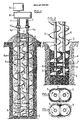
- the device represented in FIGS. 1 and 2 and used to produce columns of stable and compacted soil according to the method described above comprises the following elements:
- Each auger is provided at its free end with a disaggregating drilling head 3 adapted to the nature of the ground. It can be, for example, as illustrated, a helical head, or a knife.
- the distance X between the axes of the augers is less than their diameter so that the turns of the two augers are effectively engaged one in the other so as to ensure a movement or forced flow of the disaggregated ground 4 by the two augers.
- each auger also has a bore 5a which communicates with the bore of the corresponding drive shaft, thus making it possible to bring the filler material or binder dry or wet to orifices 6 arranged on the height of the barrel of each auger so as to ensure intimate mixing with the disaggregated soil.
- the length of the augers is adapted to the depth of the column to be produced. It is generally between 1/4 and 1/2 of the length of the column but it could, in certain cases, be increased until reaching the same length.
- augers instead of having a continuous helical profile, could be discontinuous, that is to say be replaced by a plurality of spaced propellers.
- a number of double bearings 7, depending on the depth of the column to be produced, are distributed over the height of the drive shafts and augers so as to maintain their parallelism.
- bearings could be replaced over the height of the drive shafts by a hollow continuous beam which could possibly be used to bring the material or filler binder at the top of the augers.
- the two drive shafts 1 are mounted on a gear reversing reduction device 8, itself connected to a motor 9, which drives them as well as the augers, rotating in opposite directions and at the same speed.
- This motor-reduction unit 8-9 can be carried by a drilling machine (not shown) installed on the surface in line with the column to be produced, either by means of a slide on which it can move longitudinally either freely or by through a translation device. Alternatively, it can be suspended from the boom of a lifting device (crane or other).
- the carrier being installed at the right of the chosen location, the shafts and augers are rotated in the direction corresponding to the screwing of the augers in the ground ( Figures 1 and 3).
- the speed of penetration is controlled so as to optimize the effect of soil disintegration.
- the filler material or binder can be introduced at any time during the drilling operation. In the case of the wet route it is pumped by a pump located on the surface through the rotating heads 10 mounted at the end of the drive shafts. In the case of the dry route it is forced using compressed air through the same heads.
- auger bores constitute independent conduits, it is possible, if desired, to feed one of the bores with a different filler material than that feeding the other bore, in order to react these materials in situ together or with the ground.
- the invention makes it possible to obtain columns of stabilized and compacted soil whose mechanical properties are very much superior to those of the columns obtained according to the prior art, without recompaction.
- a particularly interesting application of the method and the device of the invention is the stabilization of the rights of way of railway tracks.
Landscapes
- Engineering & Computer Science (AREA)
- Structural Engineering (AREA)
- Life Sciences & Earth Sciences (AREA)
- General Life Sciences & Earth Sciences (AREA)
- Mining & Mineral Resources (AREA)
- Paleontology (AREA)
- Civil Engineering (AREA)
- General Engineering & Computer Science (AREA)
- Soil Working Implements (AREA)
- Consolidation Of Soil By Introduction Of Solidifying Substances Into Soil (AREA)
- Investigation Of Foundation Soil And Reinforcement Of Foundation Soil By Compacting Or Drainage (AREA)
- Piles And Underground Anchors (AREA)
- Fertilizers (AREA)
- Crushing And Pulverization Processes (AREA)
- Earth Drilling (AREA)
- Superconductors And Manufacturing Methods Therefor (AREA)
- Tents Or Canopies (AREA)
- Conveying And Assembling Of Building Elements In Situ (AREA)
- Placing Or Removing Of Piles Or Sheet Piles, Or Accessories Thereof (AREA)
Claims (6)
dadurch gekennzeichnet, daß als Bohrwerkzeug eine Vorrichtung verwendet wird, die mindestens zwei parallele Wellen (1) aufweist, wobei jede Welle einen Bohrer (2) in Drehung versetzt, jeder Bohrer an seinem der Antriebswelle entgegengesetzten Ende mit einem Auflockerungs-Bohrkopf (3) versehen ist und der Abstand zwischen den Bohrerachsen kleiner als der Durchmesser eines Bohrers ist, die Wellen und die Schäfte (5) eine Bohrung (5a) aufweisen, die mit einer Quelle für das Zusatzmaterial verbunden ist und mindestens eine Öffnung (6), die mit dieser Bohrung in Verbindung steht, am Schaft jedes Bohrers vorgesehen ist, um das Zusatzmaterial abzugeben, die Bohrer gegensinnig ausgebildet und in entgegengesetzter Drehrichtung antreibbar sind, und die ferner eine Einrichtung zur Drehrichtungsumkehr der Bohrer aufweist,
daß der erste Schritt in der Weise verwirklicht wird, daß in den Boden die Vorrichtung eingetrieben wird, während gleichzeitig ein Zusatzmaterial durch die Öffnung (6) so abgegeben wird, daß es mit dem gelockerten Boden gemischt wird und daß der zweite Schritt nach der Drehrichtungsumkehr der Bohrer in der Weise verwirklicht wird, daß auf die Vorrichtung beim Zurückziehen eine geregelte Abstützkraft ausgeübt wird, um dem mit dem Zusatzmaterial gemischten gelockerten Boden eine Abwärtsbewegung durch die Vorrichtung hindurch aufzuprägen, welche die Tendenz hat, ihn zu verdichten.
Priority Applications (1)
| Application Number | Priority Date | Filing Date | Title |
|---|---|---|---|
| AT85400787T ATE44298T1 (de) | 1984-05-07 | 1985-04-22 | Verfahren und vorrichtung zum in situ-herstellen von pfaehlen aus verfestigter und verdichteter erde. |
Applications Claiming Priority (2)
| Application Number | Priority Date | Filing Date | Title |
|---|---|---|---|
| FR8407047A FR2563852B1 (fr) | 1984-05-07 | 1984-05-07 | Procede et dispositif pour la realisation en place de colonnes de sol stabilise et compacte. |
| FR8407047 | 1984-05-07 |
Publications (3)
| Publication Number | Publication Date |
|---|---|
| EP0161974A2 EP0161974A2 (de) | 1985-11-21 |
| EP0161974A3 EP0161974A3 (en) | 1986-06-11 |
| EP0161974B1 true EP0161974B1 (de) | 1989-06-28 |
Family
ID=9303744
Family Applications (1)
| Application Number | Title | Priority Date | Filing Date |
|---|---|---|---|
| EP85400787A Expired EP0161974B1 (de) | 1984-05-07 | 1985-04-22 | Verfahren und Vorrichtung zum in situ-Herstellen von Pfählen aus verfestigter und verdichteter Erde |
Country Status (12)
| Country | Link |
|---|---|
| US (1) | US4662792A (de) |
| EP (1) | EP0161974B1 (de) |
| JP (1) | JPH0665808B2 (de) |
| KR (1) | KR900006385B1 (de) |
| AT (1) | ATE44298T1 (de) |
| AU (1) | AU568057B2 (de) |
| DE (1) | DE3571259D1 (de) |
| FR (1) | FR2563852B1 (de) |
| HK (1) | HK32990A (de) |
| PH (1) | PH22602A (de) |
| PT (1) | PT80396B (de) |
| SG (1) | SG81989G (de) |
Cited By (4)
| Publication number | Priority date | Publication date | Assignee | Title |
|---|---|---|---|---|
| DE4219150C1 (en) * | 1992-06-11 | 1993-09-23 | Bauer Spezialtiefbau Gmbh, 86529 Schrobenhausen, De | Underground mortar column prodn. - by drilling with auger through which hardenable suspension is fed |
| DE10238646B3 (de) * | 2002-08-23 | 2004-04-01 | Bauer Spezialtiefbau Gmbh | Dichte Mixed-in-Place-Wände |
| DE10327470B3 (de) * | 2003-06-18 | 2004-09-30 | Bauer Spezialtiefbau Gmbh | Vorrichtung zur Herstellung von Einzelschlitzen oder durchgehenden Wänden im Erdreich nach dem Mixed-in-Place-Verfahren |
| DE102004005967A1 (de) * | 2004-02-06 | 2005-09-08 | Bauer Spezialtiefbau Gmbh | MIP-Schnecke |
Families Citing this family (33)
| Publication number | Priority date | Publication date | Assignee | Title |
|---|---|---|---|---|
| US4844839A (en) * | 1984-09-04 | 1989-07-04 | Manchak Frank | In situ treatment and analysis of wastes |
| US4776409A (en) * | 1984-09-04 | 1988-10-11 | Manchak Frank | Insitu waste impoundment treating apparatus and method of using same |
| ATE60816T1 (de) * | 1984-12-07 | 1991-02-15 | Michel Crambes | Verdichtungs-armierungs-injektions-verfahren oder auflockerungs-drainage-verfahren und bauverfahren zum erstellen von linearen und flaechenhaften bauwerken im boden. |
| US5118223A (en) * | 1988-03-23 | 1992-06-02 | Osamu Taki | Multi-shaft auger apparatus and process for forming soilcrete columns and walls and grids in situ in soil |
| US4906142A (en) * | 1988-03-23 | 1990-03-06 | S.M.W. Seiko, Inc. | Side cutting blades for multi-shaft auger system and improved soil mixing wall formation process |
| US4886400A (en) * | 1988-03-23 | 1989-12-12 | S.M.W. Seiko, Inc. | Side cutting blades for multi-shaft auger system and improved soil mixing wall formation process |
| DE3831547A1 (de) * | 1988-09-16 | 1990-03-22 | Bauer Spezialtiefbau | Verfahren zur herstellung einer moertelsaeule im erdreich |
| US5007770A (en) * | 1989-12-04 | 1991-04-16 | Simmons Robert J | Method and apparatus for constructing a subsurface retaining wall |
| EP0436954B1 (de) * | 1990-01-11 | 1994-10-05 | Seiko Kogyo Kabushiki Kaisha | Doppelrohreinrichtung zum Bohren und Kneten und Methode zur Verbesserung von Fundamentgrund mit dieser Doppelrohreinrichtung zum Bohren und Kneten |
| JPH07119462B2 (ja) * | 1991-11-15 | 1995-12-20 | 大商新基株式会社 | 地盤改良用攪拌装置及びそれを使用した地盤改良工法 |
| US5417522A (en) * | 1993-09-23 | 1995-05-23 | S. M. W. Seiko | Soil fragmentation members and multiple lateral support structures for improved soil mixing and efficient boring for use on multi-shaft auger soil mixing apparatus |
| US5378085A (en) * | 1993-10-01 | 1995-01-03 | S. M. W. Seiko | Methods for in situ construction of deep soil-cement structures |
| FR2715177B1 (fr) * | 1994-01-14 | 1996-03-01 | Sif | Dispositif perfectionné pour la réalisation en place de colonnes de sol stabilisé et compacté. |
| JP2844165B2 (ja) * | 1994-03-07 | 1999-01-06 | 富士男 板垣 | 建築物の沈下修正工法 |
| FR2724189B1 (fr) | 1994-09-02 | 1996-12-27 | Augarde Jacques | Procede et dispositif de compactage |
| JP2804002B2 (ja) * | 1995-04-14 | 1998-09-24 | 武一 渡辺 | 既設家屋の補強構造及び補強工法 |
| DE19538764A1 (de) * | 1995-10-18 | 1997-04-24 | Ursel Ramm | Vorrichtung und Verfahren zum Setzen von Trägern und dergleichen |
| NL1002285C2 (nl) * | 1996-02-09 | 1997-08-12 | Dredging Int | Inbreng van een massa door de vertikale verplaatsing van een grondmassa. |
| DE19642711A1 (de) * | 1996-10-16 | 1998-04-23 | Klemm Ingrid | Vorrichtung und Verfahren zur kontrollierten Herstellung von Pfählen oder Pfahlwänden im Boden |
| FR2758577B1 (fr) * | 1997-01-22 | 1999-03-12 | Menard Soltraitement | Procede, dispositif et materiaux pour consolider un terrain meuble et/ou compressible destine en particulier a recevoir sur lui un edifice |
| EP0911449A1 (de) * | 1997-10-24 | 1999-04-28 | Yinsheng Shi | Ortbetonpfahl und Verfahren zur Herstellung |
| US6183166B1 (en) * | 1999-04-01 | 2001-02-06 | Verne L. Schellhorn | Method of centrifugally forming a subterranean soil-cement casing |
| DE10308540B4 (de) * | 2003-02-27 | 2005-02-17 | Bauer Maschinen Gmbh | Verfahren und Vorrichtung zum Herstellen eines Gründungselementes |
| DE10354624B3 (de) * | 2003-11-22 | 2005-05-04 | Gudehus, Gerd, Prof. Dr.-Ing. | Verfahren und Vorrichtung zur Stabilisierung von weichem Boden |
| ITTO20050682A1 (it) * | 2005-09-30 | 2007-04-01 | Soilmec Spa | Metodo ed attrezzatura per realizzare un diaframma impermeabile di pali secanti. |
| GB2437960B (en) * | 2006-05-08 | 2008-08-13 | Aqs Holdings Ltd | Ground engineering method |
| DE102006028473A1 (de) * | 2006-06-21 | 2007-12-27 | Winter Von Adlersflügel, Johannes Bernhard | Füllaggregat |
| US10161097B2 (en) * | 2012-05-23 | 2018-12-25 | Ext Co., Ltd. | Hybrid foundation structure, and method for building same |
| DE102012218285A1 (de) * | 2012-10-08 | 2014-04-10 | Bauer Maschinen Gmbh | Vorrichtung und Verfahren zum Erstellen einer Gründung und Gründung |
| GB2525147B (en) * | 2014-01-27 | 2020-09-09 | Mmi Engineering Ltd | Pile insertion |
| CN104727313A (zh) * | 2015-04-12 | 2015-06-24 | 张璐 | 四头钻搅拌钻机 |
| CN105200986A (zh) * | 2015-09-15 | 2015-12-30 | 宜兴市周铁镇生力钻探机械厂 | 一种单轴相对搅拌装置 |
| CN106149695A (zh) * | 2016-07-13 | 2016-11-23 | 于洋 | 咬合v型钻机 |
Family Cites Families (10)
| Publication number | Priority date | Publication date | Assignee | Title |
|---|---|---|---|---|
| US3391544A (en) * | 1966-12-05 | 1968-07-09 | Intrusion Prepakt Inc | Means and method of forming concrete piles |
| US3875751A (en) * | 1967-06-14 | 1975-04-08 | Kjeld F W Paus | Strengthening cohesive soils |
| NL7113163A (de) * | 1970-10-01 | 1972-04-05 | ||
| US4072017A (en) * | 1974-10-11 | 1978-02-07 | Hisashi Shiraki | Treating soil |
| JPS5234508A (en) * | 1975-09-10 | 1977-03-16 | Takenaka Komuten Co | Poor subsoil improving machine |
| JPS5249612A (en) * | 1975-10-16 | 1977-04-20 | Takenaka Komuten Co | Treating apparatus for solidifying surface sludge |
| JPS5385906A (en) * | 1977-01-06 | 1978-07-28 | Sato Kouichi | Screw type reverse rotation highhpressure jet construction method |
| DE2755677A1 (de) * | 1977-12-14 | 1979-06-21 | Karlheinz Dipl Ing Dr In Bauer | Verfahren und vorrichtung zum herstellen von schlitzen im erdreich |
| JPS54137814A (en) * | 1978-04-17 | 1979-10-25 | Shimizu Construction Co Ltd | Method of creation construction of place driving pile row wall and its earthhauger device |
| US4537536A (en) * | 1983-10-18 | 1985-08-27 | The Shimizu Construction Co., Ltd. | Process and apparatus of constructing a water tight underground pile wall |
-
1984
- 1984-05-07 FR FR8407047A patent/FR2563852B1/fr not_active Expired
-
1985
- 1985-04-22 DE DE8585400787T patent/DE3571259D1/de not_active Expired
- 1985-04-22 AT AT85400787T patent/ATE44298T1/de not_active IP Right Cessation
- 1985-04-22 EP EP85400787A patent/EP0161974B1/de not_active Expired
- 1985-04-23 AU AU41628/85A patent/AU568057B2/en not_active Ceased
- 1985-04-26 KR KR1019850002839A patent/KR900006385B1/ko not_active Expired
- 1985-04-29 PH PH32201A patent/PH22602A/en unknown
- 1985-05-02 JP JP60093923A patent/JPH0665808B2/ja not_active Expired - Lifetime
- 1985-05-02 US US06/729,798 patent/US4662792A/en not_active Expired - Lifetime
- 1985-05-06 PT PT80396A patent/PT80396B/pt not_active IP Right Cessation
-
1989
- 1989-12-20 SG SG819/89A patent/SG81989G/en unknown
-
1990
- 1990-04-26 HK HK329/90A patent/HK32990A/xx not_active IP Right Cessation
Cited By (4)
| Publication number | Priority date | Publication date | Assignee | Title |
|---|---|---|---|---|
| DE4219150C1 (en) * | 1992-06-11 | 1993-09-23 | Bauer Spezialtiefbau Gmbh, 86529 Schrobenhausen, De | Underground mortar column prodn. - by drilling with auger through which hardenable suspension is fed |
| DE10238646B3 (de) * | 2002-08-23 | 2004-04-01 | Bauer Spezialtiefbau Gmbh | Dichte Mixed-in-Place-Wände |
| DE10327470B3 (de) * | 2003-06-18 | 2004-09-30 | Bauer Spezialtiefbau Gmbh | Vorrichtung zur Herstellung von Einzelschlitzen oder durchgehenden Wänden im Erdreich nach dem Mixed-in-Place-Verfahren |
| DE102004005967A1 (de) * | 2004-02-06 | 2005-09-08 | Bauer Spezialtiefbau Gmbh | MIP-Schnecke |
Also Published As
| Publication number | Publication date |
|---|---|
| AU4162885A (en) | 1985-11-14 |
| AU568057B2 (en) | 1987-12-10 |
| SG81989G (en) | 1990-09-07 |
| EP0161974A3 (en) | 1986-06-11 |
| FR2563852A1 (fr) | 1985-11-08 |
| FR2563852B1 (fr) | 1987-06-26 |
| ATE44298T1 (de) | 1989-07-15 |
| HK32990A (en) | 1990-05-04 |
| KR850008511A (ko) | 1985-12-18 |
| EP0161974A2 (de) | 1985-11-21 |
| PT80396B (pt) | 1987-05-29 |
| PH22602A (en) | 1988-10-17 |
| US4662792A (en) | 1987-05-05 |
| JPS6145022A (ja) | 1986-03-04 |
| JPH0665808B2 (ja) | 1994-08-24 |
| PT80396A (fr) | 1985-06-01 |
| DE3571259D1 (en) | 1989-08-03 |
| KR900006385B1 (ko) | 1990-08-30 |
Similar Documents
| Publication | Publication Date | Title |
|---|---|---|
| EP0161974B1 (de) | Verfahren und Vorrichtung zum in situ-Herstellen von Pfählen aus verfestigter und verdichteter Erde | |
| US3690109A (en) | Method and means for producing pile or like structural columns in situ | |
| CN1111230C (zh) | 砼钻孔灌注桩的钻孔制桩方法及其所用钻机 | |
| US2782605A (en) | Process and apparatus for grouting porous formations | |
| US5219246A (en) | Drills for piles and soil stabilization, and drilling method | |
| EP0240493B1 (de) | Verdichtungs-armierungs-injektions-verfahren oder auflockerungs-drainage-verfahren und bauverfahren zum erstellen von linearen und flächenhaften bauwerken im boden | |
| EP0663475B1 (de) | Vorrichtung zur vor Ort-Herstellung von Pfählen aus verfestigter und verdichteter Erde | |
| CN102037190B (zh) | 用于开挖和搅拌土壤的设备 | |
| CA2132660A1 (en) | Soil fragmentation members and multiple lateral support structures for improved soil mixing and efficient boring for use on multi-shaft auger soil mixing apparatus | |
| US4958962A (en) | Methods of modifying the structural integrity of subterranean earth situs | |
| GB2377235A (en) | Drilling tool | |
| US3485052A (en) | Method and means for forming concrete piles | |
| US3807184A (en) | Method and means for producing pile or like structural columns in situ | |
| JP6110903B2 (ja) | 地中埋設杭撤去方法 | |
| JP5700611B1 (ja) | 地中埋設杭撤去方法、及び地中埋設杭撤去装置 | |
| FR2648839A1 (fr) | Pieux de fondation, procedes, outils et machines pour la construction desdits pieux | |
| KR20190106116A (ko) | 원통형 말뚝 시공장치 및 테이퍼형 말뚝 시공장치와 테이퍼형 말뚝 시공방법 | |
| DE3831547A1 (de) | Verfahren zur herstellung einer moertelsaeule im erdreich | |
| GB2316700A (en) | Bearing capacity enhancement for piling applications | |
| US6988856B2 (en) | Large scale soil processing tool for use with a preformed sacrificial guide | |
| EP0565411B1 (de) | Verfahren um eine wasserundurchlässige unterirdische Schicht zu realisieren und damit hergestellte Schicht | |
| JPH0913372A (ja) | 杭工法 | |
| JP4195707B2 (ja) | 改良体の形成に使用するスクリュー軸 | |
| DE19651586C2 (de) | Bohrvorrichtung für Teilverdrängungspfähle | |
| BE1032682B1 (nl) | Werkwijze en inrichting voor het aanbrengen van trek- of drukpalen in de grond |
Legal Events
| Date | Code | Title | Description |
|---|---|---|---|
| PUAI | Public reference made under article 153(3) epc to a published international application that has entered the european phase |
Free format text: ORIGINAL CODE: 0009012 |
|
| AK | Designated contracting states |
Designated state(s): AT BE CH DE FR GB IT LI LU NL SE |
|
| PUAL | Search report despatched |
Free format text: ORIGINAL CODE: 0009013 |
|
| AK | Designated contracting states |
Kind code of ref document: A3 Designated state(s): AT BE CH DE FR GB IT LI LU NL SE |
|
| 17P | Request for examination filed |
Effective date: 19860924 |
|
| 17Q | First examination report despatched |
Effective date: 19880316 |
|
| GRAA | (expected) grant |
Free format text: ORIGINAL CODE: 0009210 |
|
| AK | Designated contracting states |
Kind code of ref document: B1 Designated state(s): AT BE CH DE FR GB IT LI LU NL SE |
|
| REF | Corresponds to: |
Ref document number: 44298 Country of ref document: AT Date of ref document: 19890715 Kind code of ref document: T |
|
| GBT | Gb: translation of ep patent filed (gb section 77(6)(a)/1977) | ||
| REF | Corresponds to: |
Ref document number: 3571259 Country of ref document: DE Date of ref document: 19890803 |
|
| ITF | It: translation for a ep patent filed | ||
| PLBE | No opposition filed within time limit |
Free format text: ORIGINAL CODE: 0009261 |
|
| STAA | Information on the status of an ep patent application or granted ep patent |
Free format text: STATUS: NO OPPOSITION FILED WITHIN TIME LIMIT |
|
| 26N | No opposition filed | ||
| ITTA | It: last paid annual fee | ||
| EPTA | Lu: last paid annual fee | ||
| EAL | Se: european patent in force in sweden |
Ref document number: 85400787.9 |
|
| REG | Reference to a national code |
Ref country code: CH Ref legal event code: PFA Free format text: SONDAGES INJECTIONS FORAGES ''S.I.F.'' ENTREPRISE BACHY TRANSFER- SOLETANCHE BACHY FRANCE |
|
| REG | Reference to a national code |
Ref country code: FR Ref legal event code: TP Ref country code: FR Ref legal event code: CD |
|
| NLS | Nl: assignments of ep-patents |
Owner name: SOLETANCHE BACHY FRANCE |
|
| NLT1 | Nl: modifications of names registered in virtue of documents presented to the patent office pursuant to art. 16 a, paragraph 1 |
Owner name: BACHY S.A. |
|
| REG | Reference to a national code |
Ref country code: GB Ref legal event code: 732E |
|
| BECA | Be: change of holder's address |
Free format text: 20000126 *SOLETANCHE BACHY FRANCE:6 RUE DE WATFORD, 92000 NANTERRE |
|
| BECH | Be: change of holder |
Free format text: 20000126 *SOLETANCHE BACHY FRANCE |
|
| BECN | Be: change of holder's name |
Effective date: 20000126 |
|
| REG | Reference to a national code |
Ref country code: GB Ref legal event code: IF02 |
|
| PGFP | Annual fee paid to national office [announced via postgrant information from national office to epo] |
Ref country code: FR Payment date: 20040224 Year of fee payment: 20 |
|
| PGFP | Annual fee paid to national office [announced via postgrant information from national office to epo] |
Ref country code: AT Payment date: 20040316 Year of fee payment: 20 |
|
| PGFP | Annual fee paid to national office [announced via postgrant information from national office to epo] |
Ref country code: SE Payment date: 20040318 Year of fee payment: 20 |
|
| PGFP | Annual fee paid to national office [announced via postgrant information from national office to epo] |
Ref country code: NL Payment date: 20040325 Year of fee payment: 20 |
|
| PGFP | Annual fee paid to national office [announced via postgrant information from national office to epo] |
Ref country code: DE Payment date: 20040326 Year of fee payment: 20 |
|
| PGFP | Annual fee paid to national office [announced via postgrant information from national office to epo] |
Ref country code: GB Payment date: 20040416 Year of fee payment: 20 |
|
| PGFP | Annual fee paid to national office [announced via postgrant information from national office to epo] |
Ref country code: LU Payment date: 20040427 Year of fee payment: 20 |
|
| PGFP | Annual fee paid to national office [announced via postgrant information from national office to epo] |
Ref country code: CH Payment date: 20040428 Year of fee payment: 20 |
|
| PGFP | Annual fee paid to national office [announced via postgrant information from national office to epo] |
Ref country code: BE Payment date: 20040511 Year of fee payment: 20 |
|
| PG25 | Lapsed in a contracting state [announced via postgrant information from national office to epo] |
Ref country code: GB Free format text: LAPSE BECAUSE OF EXPIRATION OF PROTECTION Effective date: 20050421 |
|
| PG25 | Lapsed in a contracting state [announced via postgrant information from national office to epo] |
Ref country code: NL Free format text: LAPSE BECAUSE OF EXPIRATION OF PROTECTION Effective date: 20050422 |
|
| BE20 | Be: patent expired |
Owner name: *SOLETANCHE BACHY FRANCE Effective date: 20050422 |
|
| REG | Reference to a national code |
Ref country code: GB Ref legal event code: PE20 |
|
| EUG | Se: european patent has lapsed | ||
| REG | Reference to a national code |
Ref country code: CH Ref legal event code: PL |
|
| NLV7 | Nl: ceased due to reaching the maximum lifetime of a patent |
Effective date: 20050422 |
|
| BE20 | Be: patent expired |
Owner name: *SOLETANCHE BACHY FRANCE Effective date: 20050422 |