EP0162151A1 - Optisches Mehrzeilen-Lesegerät für die maschinelle Zeichenerkennung - Google Patents
Optisches Mehrzeilen-Lesegerät für die maschinelle Zeichenerkennung Download PDFInfo
- Publication number
- EP0162151A1 EP0162151A1 EP84116325A EP84116325A EP0162151A1 EP 0162151 A1 EP0162151 A1 EP 0162151A1 EP 84116325 A EP84116325 A EP 84116325A EP 84116325 A EP84116325 A EP 84116325A EP 0162151 A1 EP0162151 A1 EP 0162151A1
- Authority
- EP
- European Patent Office
- Prior art keywords
- image
- reading device
- unit
- evaluation
- scanning
- Prior art date
- Legal status (The legal status is an assumption and is not a legal conclusion. Google has not performed a legal analysis and makes no representation as to the accuracy of the status listed.)
- Granted
Links
Images


Classifications
-
- G—PHYSICS
- G06—COMPUTING OR CALCULATING; COUNTING
- G06V—IMAGE OR VIDEO RECOGNITION OR UNDERSTANDING
- G06V30/00—Character recognition; Recognising digital ink; Document-oriented image-based pattern recognition
- G06V30/10—Character recognition
- G06V30/14—Image acquisition
- G06V30/142—Image acquisition using hand-held instruments; Constructional details of the instruments
Definitions
- the invention relates to an optical reading device according to the preamble of patent claim 1.
- Optical readers of this type are generally known in particular as hand-held readers and have been used successfully.
- DE-PS 28 17 341 describes an optical hand-held reader for machine character recognition, which is manually guided relative to a character line via a data carrier in any direction at a predetermined maximum speed.
- Such devices are used as peripheral data acquisition devices. This type of use is intended on the one hand to have a wide range of applications e.g. for connecting to cash register terminals in retail, reading labels or bank terminals for reading account numbers on customer checks, for calling up data via a display device from central files after reading the information on an ID card. sen, but also means more difficult character recognition.
- Such optical handheld readers generally consist of a scanning unit with a photodiode matrix contained therein and the actual processing unit downstream of the scanning unit that performs the character recognition.
- a typical scanning unit with a two-dimensional photodiode matrix is, for example, in DE-OS 18 16 325 described.
- Typical evaluation units are known from DE-PS 28 17 341 and DE-PS 28 16 839.
- the object of the invention is to design an optical reader of the type mentioned at the outset in such a way that a plurality of rows of lines can be detected simultaneously in one scanning operation.
- the optical reading device should be simple and inexpensive and should quickly process the characters to be scanned.
- an evaluation unit is assigned to each print line to be detected, the evaluation units being connected in parallel with one another.
- an image switch which consists of the image from the sensor field, i.e. the overall signal image emitted from the photodiode matrix forms individual signal images of the same size and then feeds the individual signal images separately to the evaluation units.
- a photodiode matrix and evaluation units are used, which are provided per se for detecting only one print line.
- the total signal image emanating from the photodiode matrix is broken down into two individual images in the image switch and these individual images are virtually supplemented to the extent that individual images result in a dimensioning that correspond to the overall signal image.
- these virtually enlarged individual signal images can be processed by the known evaluation units without having to be specially changed.
- the reader becomes particularly insensitive to directional fluctuations when scanning.
- the image contains a pixel counting device with a coupled decoder direction.
- a logic circuit arrangement with associated synchronization device is linked to the decoding device.
- the image signals of the sensor field taken over by the scanning unit are fed to the evaluation units.
- the reading device can be designed both as a hand-held reading device with a scanning unit guided manually over the data carrier and as a machine reader.
- An optical two-line hand-held reader for machine character recognition of so-called OCR plain text consists, as shown in FIG. 1, of a scanning unit AE which is housed in a pistol-like housing G in a known manner and which comprises a light source for illuminating and a sensor field Contains photodiode matrix for scanning a scanning window of a data carrier.
- the scanning unit is guided by hand over a data carrier D provided with OCR characters, in which case the photodiode matrix accommodated in the housing G generates so-called video signals in accordance with the characters image signals.
- These video signals are processed and analyzed accordingly in a processing unit VE and then on external data terminals DT which e.g. Data display devices, printers or the like can be shown.
- a keyboard TA linked to the processing unit VE serves e.g. for commissioning the device and for selecting the files storing the recognized characters.
- the processing unit VE contains an electronic image switch BW, which, as described in more detail below, breaks down the overall signal image for two print lines supplied by the photodiode matrix FM of the scanning unit into two individual signal images for one print line each and feeds these individual signal images to evaluation units AA and AB.
- the evaluation unit AA and AB correspond in their structure to the known evaluation units for single-line handheld readers (DE-PS 28 17 341, DE-PS 28 16 839).
- a multiplex unit M connected downstream of the evaluation units AA and AB retrieves the images processed and recognized in the evaluation units AA and AB from these evaluation units and leads them to the data terminal DT for display via a keyboard adaptation circuit TAA to.
- the multiplex unit M is a multiplexing unit constructed in the known manner.
- the keyboard adaptation unit TAA is known from single-line handheld devices.
- the optical two-line hand-held reader contains a photodiode matrix FM of 16 ⁇ 64 photodiodes, which is shown only schematically in FIG. 2 and corresponds to 1024 individual pixels of the signal image.
- An optical system arranged in the housing of the scanning unit projects the image of the pressure cells to be read with their printing characters, in this case the characters 1 and 9, onto the photodiode matrix FM, which, according to the direction of the arrow shown, starting from the top left to the bottom right, with regard to its image information is queried.
- the image information "white” and the level 1 the image information "black” are assigned to the signal level 0 of the resulting video signal.
- the BW image now forms two individual signal images A 'and B' from the total signal of the photodiode matrix FM, which contains information for two lines, and feeds these individual signal images A 'and B', each separately, to the evaluation units AA and AB. Since these evaluation units are designed for a photodiode matrix in accordance with the size of the photodiode matrix FM, the signal images A and B of the upper and lower half of the photodiode matrix FM are virtually supplemented by the information EI, so that individual signal images A 'and B' result with regard to their Dimensioning correspond to the original overall signal blid. These virtual individual signal images A 'and B' are then fed to the corresponding evaluation units AA and AB.
- the overall signal image of this photodiode matrix FM can also be divided into two individual signal images AB, which, however, overlap in the central area of the overall signal image. This creates redundancy of the image information for this central area. Redundancy of this type has the advantage that the handheld reader only has to be moved inaccurately over the print lines of the data carrier and that there are nevertheless no malfunctions in the detection.
- the overlapping individual signal images A and B are now supplied in correspondingly large image memories BS.
- these image memories can e.g. have the size of 1024 memory points corresponding to the size of the original photodiode matrix FM of FIG. 2.
- the information of the upper and lower partial images A and B of the overall signal image of the photodiode matrix FM can be supplemented virtually as required to the size of the image memories A 'and B'.
- the evaluation units AA. and AB then call up the virtual individual signal images A 'and B' from the corresponding image memories BS.
- the BW switch is designed as an independent unit and can be connected to corresponding connector elements S1, 52, S3 with appropriate connector elements SE, SA 'and SB of the test unit and the evaluation units AA and AB.
- the simple M also multi-cell handheld readers gives OEG friendliness of closed assembly both Einzeilenals build.
- the connector SA of the evaluation unit AA is connected directly to the connector SE of the scanning unit AE, with the omission of the image switch BW.
- the evaluation units AA and AB now contain clock generators, not shown here, in a known manner. They generate control clocks T for driving a pixel counter BZ in the image switch BW and for controlling the scanner in the scanning unit AE. Both clock generators run continuously, but due to e.g. through a network connection, synchronously.
- the sensor field (photodiode matrix) FM is queried in accordance with FIG. 4 in the cycle of the clock T starting from the evaluation unit AA, starting from the top left at pixel 0 to the bottom right to pixel 1023. 1024 pixels are therefore queried.
- the video signal VID thus obtained is fed to the image switch BW via the plug 51.
- the pictorial contains a pixel counter BZ with a downstream decoding direction DK.
- a decoding device DK Connected to the decoding device DK is a logic circuit arrangement L and a synchronization device SY.
- the Büds3-g-VID incoming from the scanning unit AE are fed to the evaluation units AA or AB.
- the decoding device converts the corresponding counter readings (0 to 1023) of the pixel counter into corresponding control signals for the subsequent logic.
- the decoding device has three outputs L1 and L2 and L3.
- the decoder then outputs control signals via line L1 when the pixels 512 to 1023 (lower half of the picture) of the photodiode matrix FM are queried.
- the line L2 is supplied with signals for the areas of the pixels 0 to 255 of the photodiode matrix FM and the line L3 for the pixel 255.
- the pixel counter BZ is linked on the input side to the clock T and, depending on this clock, counts from 0 to 1023 in accordance with the interrogation of the photodiode matrix FM.
- the frame counter is synchronized via the synchronization signal SS which is generated when the last point 1023 of the photodiode matrix FM is reached.
- the decoder controls the distribution of the video signals VID to the evaluation units AA and AB via the logic circuit arrangement L from the two AND gates U1 and U2 and the inverter I, the evaluation unit AA having the pixels 0 to 511 and the evaluation unit AB the pixels 512 to including 1023 can be fed.
- the evaluation units are designed for 1024 pixels, it is necessary to generate a so-called virtual image of 1024 pixels.
- the actual physical field is supplemented by a leading and trailing point of 256 pixels each, namely that during the scanning of the lower field B and the feed of the video signals to the evaluation unit AB, which is carried out in the evaluation unit AA during video signals actually not received at that time as "white values" Evaluates video signals.
- 1024 corresponding pixels are built up in the corresponding evaluation electronics AA and AB, which only contain the information from the photodiode matrix FM in the middle part.
- the required follow-up and advance of 256 pixels for the virtual images A 'and B' is generated via the synchronization direction SY.
- the synchronous signal SCB for the end of the virtual image B 1 , is generated via the AND gate U4, specifically with the clock generator T running (the clock generators for AA and AB run synchronously) and when the scanning in the range of pixels 0 to 255 (L2) and the 255 pixel (L3) is reached.
- the reading device can be designed both as a hand-held reading device with a print line that is manually guided over the data carrier and as a machine reading device in which the scanner is moved mechanically relative to the data carrier.
Landscapes
- Engineering & Computer Science (AREA)
- Computer Vision & Pattern Recognition (AREA)
- Physics & Mathematics (AREA)
- General Physics & Mathematics (AREA)
- Multimedia (AREA)
- Theoretical Computer Science (AREA)
- Character Input (AREA)
- Facsimile Scanning Arrangements (AREA)
Abstract
Description
- Die Erfindung betrifft ein optisches Lesegerät gemäß dem Oberbegriff des Patentanspruchs 1.
- Derartige optische Lesegeräte sind insbesondere als Handlesegerät allgemein bekannt und mit Erfolg zur Anwendung gelangt. So wird in der DE-PS 28 17 341 ein optisches Handlesegerät für eine maschinelle Zeichenerkennung beschrieben, das manuell relativ zu einer Zeichenzeile über einen Datenträger in beliebiger Richtung mit einer vorgegebenen maximalen Geschwindigkeit geführt wird.
- Solche Geräte werden als periphere Datenerfassungsgeräte eingesetzt. Diese Art der Verwendung soll einerseits einen weiten Anwendungsbereich z.B. zum Anschluß an Kassenterminals im Handel, zum Lesen von Etiketten oder an Bankenterminals zum Lesen von Kontonummern auf Kundenschecks, zum Abruf von Daten über ein Sichtgerät aus zentralen Datein nach Lesen der Information auf einem Ausweis erschlies. sen, bedeutet aber andererseits auch eine schwierigere Zeichenerkennung..
- Derartige optische Handlesegeräte bestehen dabei im allgemeinen aus einer Abtasteinheit mit einer darin enthaltenen Fotodiodenmatrix und der eigentlichen der Abtasteinheit nachgeschalteten die Zeichenerkennung durchführenden Verarbeitungseinheit.
- Eine typische Abtasteinheit mit einer zweidimensional aufgebauten Fotodiodenmatrix ist z.B. in der DE-OS 18 16 325 beschrieben. Typische Auswerteelnheiten sind aus der DE-PS 28 17 341 und der DE-PS 28 16 839 bekannt.
- Auf Kassenetiketten und Verpackungen, Z.B. auf der Pharmaindustrie Ist es üblich, die Informationen über den Preis und den Inhalt in Klarschrift (OCR-Schrlft) in zwei Zeilen anzuordnen.
- Zum Lesen derartiger mehrzeiliger Informationen in Klarschrift ist es üblich, die bekannten Ein-Zeiien-Handiesegeräte zuverwenden und dabei den Lesekopf des Einzeilen-Handlesers nacheinander über die einzelnen Zeilen des Datenträgers zu führen.
- Eine derartige Folgeabtastung erfordert nun relativ viel Zeit, insbesondere bei der Verwendung derartiger Handlesegeräte in Verbindung mit Kassenterminals wird das Handling beeinträchtigt, da die Bedienperson den Lesekopf mehrfach über den Datenträger führen muß. Dies erfordert von der Bedienperson erhöhte Aufmerksamkeit und ist eine zusätzliche Fehlerquelle.
- Aufgabe der Erfindung Ist es, ein optisches Lesegerät der eingangs genannten Art so auszugestalten, daß bei einem Abtastvorgang mehrere Zeiahenzeilen gleichzeitig erfaßt werden können. Das optische Lesegerät soll dabei einfach und kostengünstig ausgestaltet sein und eine schnelle Verarbeitung der abzutastenden Zeichen bewerkstelligen.
- Diese Aufgabe wird bei einem optischen Lesegerät der eingangs genannten Art gemäß dem kennzeichnenden Teil des ersten Patentanspruches gelöst.
- Weitere vorteilhafte Ausführungsformen der Erfindung sind in den Unteransprüchen gekennzeichnet.
- Bei dem erfindungsgemäßen Lesegerät ist jeder zu erfassenden Druckzeile eine Auswerteeinheit zugeordnet, wobei die Auswerteeinheiten untereinander parallel geschaltet sind. Zwischen der Abtasteinheit und den Auswerteeinheiten befindet sich eine Bildweiche, die aus dem vom Sensorfeld, d.h. der Fotodiodenmatrix abgegebenen Gesamtsignalbild gleich große Einzelsignalbilder bildet und dann die Einzelsignalbilder getrennt den Auswerteeinheiten zuführt .
- Damit ist eine sehr schnelle Parallelverarbeitung der von der Abtasteinheit in einem Abtastvorgang erfaßten Druckzeilen möglich.
- Bei einer vorteilhaften Ausführungsform der Erfindung wird eine Fotodiodenmatrix und Auswerteeinheiten verwendet, die an sich zum Erfassen von nur einer Druckzeile vorgesehen sind. Dazu wird in der Bildweiche das von der Fotodiodenmatrix ausgehende Gesamtsignalbild in zwei Einzelbilder zerlegt und diese Einzelbilder virtuell soweit ergänzt, daß sich Einzelbilder in einer Dimensionierung ergeben, die dem Gesamtsignalbild entsprechen. Damit können diese virtuell vergrößerten Einzelsignalbilder von den bekannten Auswerteeinheiten verarbeitet werden, ohne daß diese besonders verändert werden müssen .
- Gestaltet man die Aufteilung der Einzelsignalbilder hinsichtlich dem Gesamtsignalbild so, daß sich die Einzelsignalbilder im Bereich der Mitte des Gesamtsignalbildes überlappen, so wird das Lesegerät gegenüber Richtungs- schwankungen beim Abtasten besonders unempfindlich.
- Der "Fangbereich" für die einzelnen Zellen des mehrzelligen Datenträgers wird dadurch erweitert.
- Bei einer vorteilhaften Ausführungsform der Erfindung enthält die Bildwelche eine Bildpunktzähleinrichtung mit gekoppelter Dekodlerelnrichtung. Mit der Dekodiereineinrichtung verknüpft ist eine logische Schaltungsanordnung mit zugehöriger Synchrenisiereinrichtung. In Abhängigkeit von Zählerstand der Bildpunktzähleinrichtung werden dabei die von der Abtasteinheit übernommenen Bildsignale des Sensorfeldes den Auswerteeinheiten zugeführt. Durch eine derartige Realisierung der Bildweiche wird das Handlesegerät besonders betriebssicher und störungsunanfällig.
- Das Lesegerät kann sowohl als Handlesegerät mit manuell über den Datenträger geführte Abtasteinheit, als auch als maschineller Leser ausgebildet sein.
- Ausführungsformen der Erfindung sind in den Zeichnungen dargestellt und werden im folgenden beispielsweise näher beschrieben. Es zeigen
- Fig. 1 ein Blockschaltbild eines optischen Zweizeilenhandlesegerätes,
- Fig. 2 eine schematische Darstellung der aus dem Signalbild des Sensorfeldes gewonnenen Einzelsignalbildes für die Auswerteelnheiten eines Zweizellenhandläseoerätes.
- Fig 3 eine schematische Darstellung der Generierung der Einzelslgnalbllder aus dem Signalbild des Sensorfeldes für ein Zweizellenhandlesegeriit bei dem sich die Einzelsignalbilder im mittleren Bereich des Sensorfeldes überlappen,
- Fig. 4 eine scheeatische Darstellung der Bildrastererzeugung bei einem Zweizeilenhandlesegerät entsprechend der Fig. 2 und
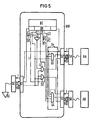
- Fig. 5 ein Blockschaltbild der Bildweiche.
- Ein optisches Zweizeilen-Handlesegerät für die maschinelle Zeichenerkennung von sogenannter OCR-Klarschrift besteht gemäß der Darstellung der Fig. 1 aus einer Abtasteinheit AE die in bekannter Weise in einem pistolenartigen Gehäuse G untergebracht ist und die eine Lichtquelle zum Be- leuchten und ein Sensorfeld aus einer Fotodiodenmatrix zum Abtasten eines Abtastfensters eines Datenträgers enthält. Die Abtasteinheit wird dabei von Hand über einen mit OCR-Schriftzeichen versehenen Datenträger D geführt, wobei dann die im Gehäuse G untergebrachte Fotodiodenmatrix entsprechend den Schriftzeichen Bildsignale sogenannte Videosignale, erzeugt. Diese Videosignale werden an in einer Verarbeitungseinheit VE entsprechend aufbereitet und analysiert und dann auf externen Datenterminals DT die z.B. Datensichtgeräte, Drucker oder ähnliches sein können, dargestellt. Eine mit der Verarbeitungseinheit VE verknüpfte Tastatur TA dient z.B. zur Inbetriebnahme des Gerätes und zur Auswahl der die erkannten Zeichen speichernden Dateien. Die Verarbeitungseinheit VE enthält eine elektronische Bildweiche BW, die wie nachfolgend ausführlicher beschrieben das von der Fotodiodenmatrix FM der Abtasteinheit gelieferte Gesamtsignalbild für zwei Druckzeilen in zwei Einzelsignalbilder für je eine Druckzeile zerlegt und diese Einzelsignalbilder Auswerteeinheiten AA und AB zuführt. Die Auswerteeinheit AA und AB entsprechen in ihrem Aufbau den bekannten Auswerteeinheiten für Einzeilenhandlesegeräte (DE-PS 28 17 341, DE-PS 28 16 839).
- Eine den Auswerteeinheiten AA und AB nachgeschaltete Multiplexeinheit M ruft die in den Auswerteeinheiten AA und AB aufbereiteten und erkannten Bilder aus diesen Auswerteeinheiten ab und führt sie über eine Tastaturanpassungsschaltung TAA dem Datenterminal DT zur Darstellung zu. Bei der Multiplexeinheit M handelt es sich um eine nach der bekannten Art aufgebaute Multiplexelnheit. Die Tastaturanpassurgseinheit TAA ist aus Einzeilenhandiesegeräten bekannt.
- Entsprechend der Darstellung der Flg. 2 enthält das optische Zweizeilenhandlesegerät eine in der Fig. 2 nur schematisch dargestellte Fotodiodenmatrix FM aus 16 x 64 Fotodioden die 1024 einzelnen Bildpunkten des Signaibildes entsprechen. Ein im Gehäuse der Abtasteineit angeordnetes optisches System projiziert dabei das Bild der abzulesenden Druckzellen mit ihren Druckzeichen, in diesem Falle die Zeichen 1 und 9, auf die Fotodiodenmatrix FM, die entsprechend der dargestellten Pfeilrichtung, beginnend von links oben nach rechts unten, hinsichtlich ihrer Bildinformation abgefragt wird. Dabei wird dem Signalpegel 0 des resultierenden Videoslgnales die Bildinformation "weiß"und den Pegel 1 die Bildinformation "schwarz" zugeordnet.
- Die Bildwelche BW bildet nun aus dem Gesamtsignal der Fotodiodenmatrix FM, die Information für zwei Zeilen enthält, zwei Einzelslgnalbllder A' und B' und führt diese Elnzelsignalbilder A' und B' jeweils getrennt den Auswerteeinheiten AA und AB zu. Da diese Auswrerteeinheiten für eine Fotordiodenmatrix entsprechend der Größe der Fotodiodenmatrix FM ausgelegt sind, werden die Signalbilder A und B der oberen und unteren Hälfte der Fotodiodenmatrix FM virtuell durch die Informationen EI ergänzt, so daß sich Einzelslgnalbilder A' und B' ergeben, die hinsichtlich ihrer Dimensionierung dem ursprünglichen Gesamtsignalblid entsprechen. Diese virtuellen Einzelsignalbilder A' und B' werden dann den entsprechenden Auswerteeinheiten AA und AB zugeführt.
- Verwendet man nun anstelle der Fotodiodenmatrix FM mit 64 Zeilen eine Fotodiodenmatrix FM entsprechend der Fig. 3 mit 100 Zeilen so läßt sich das Gesamtsignalbild dieser Fotodiodenmatrix FM ebenfalls in zwei Einzelsignalbilder AB aufteilen, die sich aber im mittleren Bereich des Gesamtsignalbildes überlappen. Dadurch entsteht für diesen mittleren Bereich eine Redundanz der Bildinformation. Derartige Redundanz hat den Vorteil, daß das Handlesegerät nur ungenau über die Druckzeilen des Datenträgers geführt werden muß und daß es trotzdem zu keinen Störungen bei der Erkennung kommt.
- Bei der dargestellten Ausführungsform entsprechend der Fig. 3 werden nun die sich überlappenden Einzelsignalbilder A und B entsprechend großen Bildspeichern BS zugeführt. Um auch bei einer derartigen Ausführungsform die bekannten Auswerteeinheiten mitverwenden zu können, können diese Bildspeicher z.B. die Größe von 1024 Speicherpunkten entsprechend der Größe der ursprünglichen Fotodiodenmatrix FM der Fig. 2 haben. Auch hier lassen sich über die Bildweiche die Informationen der oberen und unteren Teilbilder A und B des Gesamtsignalbildes der Fotodiodenmatrix FM virtuell bedarfsweise auf die Größe der Bildspeicher A' und B' ergänzen. Die Auswerteeinheiten AA . und AB rufen dann die virtuellen Einzelsignalbilder A' und B' aus den entsprechenden Bildspeichern BS ab.
- Der Aufbau und die Funktion der Bildweiche BW wird nun anhand der Fig. 4 und 5 näher beschrieben. Dabei wird bei Bildrastererzeugung in der Fig . 4 von dem in der Fig. 2 beschriebenen Prinzip Gebrauch gemacht.
- Die Bildweiche BW ist dabei als selbständige Baueinheit ausgestaltet und kann über entsprechende Steckerelemente S1, 52, S3 mit entsprechenden Steckerelementen SE, SA 'und SB der Abtestelnheit und den Auswerteelnhetien AA und AB verbunden werden. Dadurch ergibt sich die einfache Mög- lichkeit aus geschlossenen Baugruppe sowohl Einzeilenals auch Mehrzellen-Handlesegeräte aufzubauen. Beim Aufbauen eines Einzeilen-Handlesegerätes wird unter Weglassung der Bildweiche BW, der Stecker SA der Auswerteeinheit AA direkt mit dem Stecker SE der Abtasteinheit AE verbunden.
- Die Auswerteeinheiten AA und AB enthalten nun in bekannter Weise hier nicht dargestellte Taktgeneratoren. Sie erzeugen Steuertakte T zum Ansteuern eines Bildpunktzählers BZ in der Bildweiche BW und zur Steuerung des Abtasters in der Abtastelnheit AE. Beide Taktgeneratoren laufen kontinuierlich, bedingt jedoch z.B. durch eine Netzkoppelung, synchron. Im Takt des von der Auswerteeinheit AA ausgehenden Taktes T wird das Sensorfeld (Fotodiodenmatrix) FM entsprechend der Fig. 4 abgefragt und zwar beginnend links oben am Bildpunkt 0 bis rechts unten zum Bildpunkt 1023. Es werden also 1024 Punkte abgefragt. Das so gewonnene Videosignal VIDwird der Bildweiche BW über die Stecker 51 zugeführt.
- Die Bildliche enthalt einen Bildpunktzähler BZ mit nachgeschalteter Dekodierelnrichtung DK. Mit der Dekodiereinrichtung DK verbunden, ist eine logische Schaltungsanordnung L und eine Synchzonlslereinrlchtung SY. Dabei werden in Abhängigkeit vom Zählerstand der Bildpunktzähleinrichtung BZ, die von der Abtasteinheit AE eingehenden Büds3-g-nale VID den Auswerteelnheiten AA oder AB zugeführt. Die Dekodiereinrichtung setzt dabei die entsprechenden Zählerstände (0 bis 1023) des Bildpunktzählers in entsprechende Ansteuersignale für die nachfolgende Logik um.
- Die Dekodiereinrichtung hat dabei drei Ausgänge Ll und L2 und L3. Über die Leitung Ll gibt der Decodierer dann Ansteuersignale ab, wenn die Bildpunkte 512 bis 1023 (untere Bildhälfte) der Fotodiodenmatrix FM abgefragt wird. Die Leitung L2 wird mit Signalen beaufschlagt, für die Bereiche der Bildpunkte 0 bis 255 der Fotodiodenmatrix FM und die Leitung L3 für den Bildpunkt 255.
- Der Bildpunktzähler BZ ist eingangsseitig mit dem Takt T verknüpft und zählt in Abhängigkeit von diesem Takt entsprechend der Abfragung des Fotodiodenmatrix FM von 0 bis 1023. Rückgesetzt, d.h. synchronisiert wird der Bildzähler über das Synchronisiersignal SS das generiert wird, wenn der letzte Punkt 1023 der Fotodiodenmatrix FM erreicht ist.
- Der Dekodierer steuert über die logische Schaltungsanordnung L aus den beiden UND-Gliedern U1 und U2 und dem Inverter I die Verteilung der Videosignale VID zu den Auswerteeinheiten AA und AB, wobei der Auswerteeinheit AA die Bildpunkt 0 bis 511 und der Auswerteeinheit AB die Bildpunkte 512 bis einschließlich 1023 zugeführt werden.
- Da die Halbbilder jedoch nur 512 Bildpunkte enthalten, die Auswerteeinheiten aber für 1024 Bildpunkte ausgelegt sind, ist es erforderlich ein sogenanntes virtuelles Bild von 1024 Bildpunkte zu erzeugen. Zu dieser virtuellen Bilderzeugung wird das tatsächliche physikalische Halbbild durch einen Vor- und Nachlauf von je 256 Bildpunkte ergänzt und zwar dadurch, daß man während der Abtastung des unteren Halbbildes B und der dabei erfolgten Zuführung der Videosignale zur Auswerteeinheit AB, die in der Auswerteeinheit AA während dieser Zeit tatsächlich nicht eingehenden Videosignale als "Weißwerte" beinhaltende Videosignale wertet. Dadurch werden in den entsprechenden Auswerteelektroniken AA und AB jeweils 1024 Bildpunkte umfassende Bilder aufgebaut, die nur im Mittelteil die Informationen von der Fotodiodenmatrix FM enthalten. Der Vorlauf und der Nachlauf von je 256 Bildpunkten ist "weiß", da das Signal VID in der Weiche in diesen Bildphasen gesperrt ist. Diese Sperre wird dadurch erreicht, daß über das UND-GLied Ul in Verbindung mit dem Inverter I das Videosignal VID für die obere Hälfte der Fotodiodenmatrix der Auswertelektronik AA , und für den unteren Teil der Fotodiodenmatrix FM über das UND-Glied U2 der Auswerteeinhei t AB zuge führt wird.
- Der erforderliche Nachlauf und Vorlauf von 256 Bildpunkten für die virtuellen Bilder A' und B' wird über die Synchronisierelnrichtung SY erzeugt.
- Sie bildet dann ein das virtuelle Bild A' in die Auswerteeinhelt übarnehendes und damit das Ende eines Abtastbildes anzeigendes Synchronlsiersignal SCA beim Bildpunkte 1023 des virtuellen Bildes A', wenn an dem UND-Glied U3 bei laufendem Taktgenerator T der 255 Bildpunkt (L3) in der zweiten Hälfte (Bildpunkte 512 bis 1023) der Fotodiodenmatrix FM (L1) erreicht ist.
- Das Synchronlslersignal SCB, für das Ende des virtuellen Bildes B1, wird über das UND Glied U4 generiert und zwar bei laufendem Taktgenerator T (die Taktgeneratoren für AA und AB laufen synchron) und wenn die Abtastung im Bereich der Bildpunkte 0 bis 255 (L2) erfolgt und der 255 Bildpunkt (L3) erreicht ist.
- Die Erfindung wurde vorstehend anhand eines Zweizeilen-Handlesegerätes beschrieben. Wird eine gleichzeitige Abtastung von mehreren Druchzeilen gewünscht, so läßt sich dies durch entsprechende Ergänzung der Bildweiche leicht bewerkstelligen.
- Das Lesegerät kann dabei sowohl als Handlesegerät mit manuell über den Datenträger geführten Druckzeile ausgebildet sein, als auch als ein maschinelles Lesegerät bei dem der Abtaster maschineller relativ um Datenträger bewegt wird.
-
- AE Abtasteinheit
- G Gehäuse
- D Datenträger
- VE Verarbeitungseinheit
- DT Datenterminal
- TA Tastatur
- BW Bildweiche
- FM Fotodiodenmatrix
- AA Auswerteeinheiten
- AB Auswerteeinheiten
- M Multiplexeinheit
- TAA Tastaturanpassungseinheit
- A', B' Einzelsignalbilder (erweiterte)
- A, B Halbbilder (Signalbilder)
- MB mittlerer Bereich
- EJ - ergänzte Information
- BS Bildspeicher
- S1, S2, S3 Steckerelemente
- T Steuertakt
- BZ Bildpunktzähler
- VID Videosignal
- DK Dekodiereinrichtung
- L logische Schaltungsanordnung
- SY Synchronlslereinrichtung
- LI, L2, L3 Ausgänge, Dekodierer
- 5S Synchranisiersignal
- U1,U2,U3,U4 UND-Glieder
- I Inverter
- SCA2 SCB Synchzonisiersignale
- 0 - 1023 Bildpunkte
Claims (9)
dadurch gekennzeichnet , daß eine Fotodiodenmatrix (FM) und Auswerteeinheiten (AA, AB)
verwendet werden, die an sich zum Erfassen von nur einer Druckzeile vorgesehen sind, wobei die aus dem Gesamtsignalbild der Fotodiodenmatrix (FM) gewonnenen Einzelsignalbilder über die Bildweiche (BW) virtuell zu in ihrer Dimensionierung dem Gesamtsignalbild entsprechenden Einzelsignalbildern (A, B) ergänzt werden.
dadurch gekennzeichnet , daß die Einzelsignalbilder (A, B) hinsichtlich dem mittleren Bereich (MB) des Gesamtsignalbildes überlappend (redundant) ausgebildet sind.
Priority Applications (1)
| Application Number | Priority Date | Filing Date | Title |
|---|---|---|---|
| AT84116325T ATE43449T1 (de) | 1984-03-29 | 1984-12-27 | Optisches mehrzeilen-lesegeraet fuer die maschinelle zeichenerkennung. |
Applications Claiming Priority (2)
| Application Number | Priority Date | Filing Date | Title |
|---|---|---|---|
| DE3411688 | 1984-03-29 | ||
| DE3411688 | 1984-03-29 |
Publications (2)
| Publication Number | Publication Date |
|---|---|
| EP0162151A1 true EP0162151A1 (de) | 1985-11-27 |
| EP0162151B1 EP0162151B1 (de) | 1989-05-24 |
Family
ID=6232023
Family Applications (1)
| Application Number | Title | Priority Date | Filing Date |
|---|---|---|---|
| EP84116325A Expired EP0162151B1 (de) | 1984-03-29 | 1984-12-27 | Optisches Mehrzeilen-Lesegerät für die maschinelle Zeichenerkennung |
Country Status (3)
| Country | Link |
|---|---|
| EP (1) | EP0162151B1 (de) |
| AT (1) | ATE43449T1 (de) |
| DE (1) | DE3478355D1 (de) |
Citations (1)
| Publication number | Priority date | Publication date | Assignee | Title |
|---|---|---|---|---|
| US3432673A (en) * | 1967-10-06 | 1969-03-11 | Control Data Corp | Line tracking reading machine having means to positionally normalize the character-video signals |
-
1984
- 1984-12-27 EP EP84116325A patent/EP0162151B1/de not_active Expired
- 1984-12-27 DE DE8484116325T patent/DE3478355D1/de not_active Expired
- 1984-12-27 AT AT84116325T patent/ATE43449T1/de not_active IP Right Cessation
Patent Citations (1)
| Publication number | Priority date | Publication date | Assignee | Title |
|---|---|---|---|---|
| US3432673A (en) * | 1967-10-06 | 1969-03-11 | Control Data Corp | Line tracking reading machine having means to positionally normalize the character-video signals |
Non-Patent Citations (1)
| Title |
|---|
| PATENTS ABSTRACTS OF JAPAN, Band 5, Nr. 185 (P-91)[857], 25. November 1981; & JP - A - 56 114 077 (NIPPON DENKI K.K.)08.09.1981 * |
Also Published As
| Publication number | Publication date |
|---|---|
| EP0162151B1 (de) | 1989-05-24 |
| ATE43449T1 (de) | 1989-06-15 |
| DE3478355D1 (en) | 1989-06-29 |
Similar Documents
| Publication | Publication Date | Title |
|---|---|---|
| DE2632206C2 (de) | Lesevorrichtung | |
| DE69326677T2 (de) | Automatisch startendes abtastsystem | |
| DE3250064C2 (de) | Tintenstrahl-Aufzeichnungsgerät | |
| DE1549673A1 (de) | Zeichenlese- und -uebertragungsvorrichtung | |
| DE2639856A1 (de) | Ueberlagerungs-aufzeichnungsvorrichtung | |
| DE2501793A1 (de) | Druckanordnung | |
| DE1774490B2 (de) | Vorrichtung zum optischen abtasten von informationen auf gefoerderten gegenstaenden | |
| DE2457621B2 (de) | Datenverarbeitungsanlage zur Textverarbeitung mit einer einen Speicher aufweisenden Anzeigeeinrichtung | |
| DE2146497C3 (de) | Segmentierungs-Vorrichtung für optische Zeichenleser | |
| DE69321881T2 (de) | Vorrichtung zum Lesen von Strichkoden | |
| DE3109288C2 (de) | Optische Leseeinrichtung für in Balkencodeschrift codierte Zeichen | |
| DE2301335C3 (de) | Faksimile-Verfahren mit abwechselnder Verwendung einer Endstation als Empfänger oder Sender | |
| EP0516927B1 (de) | Strichcode-System | |
| EP0107083B1 (de) | Belegverarbeitungseinrichtung mit Korrekturschaltung und Datensichtgerät | |
| EP0162151B1 (de) | Optisches Mehrzeilen-Lesegerät für die maschinelle Zeichenerkennung | |
| DE2833908C2 (de) | Verfahren und Einrichtung zum automatischen Erkennen von Markierungen | |
| DE2823679C2 (de) | ||
| DE2302442A1 (de) | Verfahren und vorrichtung zum lesen von ziffern | |
| DE2716028B2 (de) | Gemischte Übermittlung von Texten, Kommandos und Instruktionen | |
| DE3121884C2 (de) | ||
| DE2347393C2 (de) | Verfahren und Vorrichtung zur Erkennung eines digitalen Code | |
| DE2746779A1 (de) | Taktgebevorrichtung bei einem ausweiskarten-lesegeraet | |
| DE2513841C3 (de) | Karten-Lesegerät | |
| DE3331911C2 (de) | Schnittstellenanordnung zur Übertragung von Fernsehbildern auf einen Drucker | |
| DE2020013C3 (de) | Verfahren zum Übertragen von Markierungen eines Formulars auf einen Datenträger |
Legal Events
| Date | Code | Title | Description |
|---|---|---|---|
| PUAI | Public reference made under article 153(3) epc to a published international application that has entered the european phase |
Free format text: ORIGINAL CODE: 0009012 |
|
| AK | Designated contracting states |
Designated state(s): AT BE CH DE FR GB IT LI NL SE |
|
| 17P | Request for examination filed |
Effective date: 19860109 |
|
| 17Q | First examination report despatched |
Effective date: 19871120 |
|
| GRAA | (expected) grant |
Free format text: ORIGINAL CODE: 0009210 |
|
| AK | Designated contracting states |
Kind code of ref document: B1 Designated state(s): AT BE CH DE FR GB IT LI NL SE |
|
| REF | Corresponds to: |
Ref document number: 43449 Country of ref document: AT Date of ref document: 19890615 Kind code of ref document: T |
|
| REF | Corresponds to: |
Ref document number: 3478355 Country of ref document: DE Date of ref document: 19890629 |
|
| ITF | It: translation for a ep patent filed | ||
| ET | Fr: translation filed | ||
| GBT | Gb: translation of ep patent filed (gb section 77(6)(a)/1977) | ||
| PLBE | No opposition filed within time limit |
Free format text: ORIGINAL CODE: 0009261 |
|
| STAA | Information on the status of an ep patent application or granted ep patent |
Free format text: STATUS: NO OPPOSITION FILED WITHIN TIME LIMIT |
|
| 26N | No opposition filed | ||
| ITTA | It: last paid annual fee | ||
| PGFP | Annual fee paid to national office [announced via postgrant information from national office to epo] |
Ref country code: CH Payment date: 19930323 Year of fee payment: 9 |
|
| PGFP | Annual fee paid to national office [announced via postgrant information from national office to epo] |
Ref country code: GB Payment date: 19931122 Year of fee payment: 10 |
|
| PGFP | Annual fee paid to national office [announced via postgrant information from national office to epo] |
Ref country code: AT Payment date: 19931124 Year of fee payment: 10 |
|
| PGFP | Annual fee paid to national office [announced via postgrant information from national office to epo] |
Ref country code: BE Payment date: 19931215 Year of fee payment: 10 |
|
| PGFP | Annual fee paid to national office [announced via postgrant information from national office to epo] |
Ref country code: SE Payment date: 19931222 Year of fee payment: 10 |
|
| PGFP | Annual fee paid to national office [announced via postgrant information from national office to epo] |
Ref country code: FR Payment date: 19931223 Year of fee payment: 10 |
|
| PG25 | Lapsed in a contracting state [announced via postgrant information from national office to epo] |
Ref country code: LI Effective date: 19931231 Ref country code: CH Effective date: 19931231 |
|
| PGFP | Annual fee paid to national office [announced via postgrant information from national office to epo] |
Ref country code: NL Payment date: 19931231 Year of fee payment: 10 |
|
| PGFP | Annual fee paid to national office [announced via postgrant information from national office to epo] |
Ref country code: DE Payment date: 19940216 Year of fee payment: 10 |
|
| REG | Reference to a national code |
Ref country code: CH Ref legal event code: PL |
|
| PG25 | Lapsed in a contracting state [announced via postgrant information from national office to epo] |
Ref country code: GB Effective date: 19941227 Ref country code: AT Effective date: 19941227 |
|
| PG25 | Lapsed in a contracting state [announced via postgrant information from national office to epo] |
Ref country code: SE Effective date: 19941228 |
|
| PG25 | Lapsed in a contracting state [announced via postgrant information from national office to epo] |
Ref country code: BE Effective date: 19941231 |
|
| EAL | Se: european patent in force in sweden |
Ref document number: 84116325.6 |
|
| BERE | Be: lapsed |
Owner name: SIEMENS A.G. BERLIN UND MUNCHEN Effective date: 19941231 |
|
| PG25 | Lapsed in a contracting state [announced via postgrant information from national office to epo] |
Ref country code: NL Effective date: 19950701 |
|
| GBPC | Gb: european patent ceased through non-payment of renewal fee |
Effective date: 19941227 |
|
| PG25 | Lapsed in a contracting state [announced via postgrant information from national office to epo] |
Ref country code: FR Effective date: 19950831 |
|
| NLV4 | Nl: lapsed or anulled due to non-payment of the annual fee |
Effective date: 19950701 |
|
| PG25 | Lapsed in a contracting state [announced via postgrant information from national office to epo] |
Ref country code: DE Effective date: 19950901 |
|
| EUG | Se: european patent has lapsed |
Ref document number: 84116325.6 |
|
| REG | Reference to a national code |
Ref country code: FR Ref legal event code: ST |