EP0162190A1 - Dispositif pour forer des formations souterraines optionellement verticalement ou en biais - Google Patents
Dispositif pour forer des formations souterraines optionellement verticalement ou en biais Download PDFInfo
- Publication number
- EP0162190A1 EP0162190A1 EP85100936A EP85100936A EP0162190A1 EP 0162190 A1 EP0162190 A1 EP 0162190A1 EP 85100936 A EP85100936 A EP 85100936A EP 85100936 A EP85100936 A EP 85100936A EP 0162190 A1 EP0162190 A1 EP 0162190A1
- Authority
- EP
- European Patent Office
- Prior art keywords
- stabilizer
- housing
- drilling
- rotary
- drill string
- Prior art date
- Legal status (The legal status is an assumption and is not a legal conclusion. Google has not performed a legal analysis and makes no representation as to the accuracy of the status listed.)
- Granted
Links
- 238000005553 drilling Methods 0.000 title claims abstract description 32
- 230000015572 biosynthetic process Effects 0.000 title claims abstract description 5
- 238000005755 formation reaction Methods 0.000 title claims abstract description 5
- 239000003381 stabilizer Substances 0.000 claims abstract description 70
- 239000011435 rock Substances 0.000 claims abstract description 4
- 238000005452 bending Methods 0.000 abstract description 15
- 238000010586 diagram Methods 0.000 description 2
- 238000006073 displacement reaction Methods 0.000 description 2
- 230000000903 blocking effect Effects 0.000 description 1
- 238000006243 chemical reaction Methods 0.000 description 1
- 239000012141 concentrate Substances 0.000 description 1
- 230000008878 coupling Effects 0.000 description 1
- 238000010168 coupling process Methods 0.000 description 1
- 238000005859 coupling reaction Methods 0.000 description 1
- 230000005484 gravity Effects 0.000 description 1
- 230000000717 retained effect Effects 0.000 description 1
Images


Classifications
-
- E—FIXED CONSTRUCTIONS
- E21—EARTH OR ROCK DRILLING; MINING
- E21B—EARTH OR ROCK DRILLING; OBTAINING OIL, GAS, WATER, SOLUBLE OR MELTABLE MATERIALS OR A SLURRY OF MINERALS FROM WELLS
- E21B17/00—Drilling rods or pipes; Flexible drill strings; Kellies; Drill collars; Sucker rods; Cables; Casings; Tubings
- E21B17/20—Flexible or articulated drilling pipes, e.g. flexible or articulated rods, pipes or cables
-
- E—FIXED CONSTRUCTIONS
- E21—EARTH OR ROCK DRILLING; MINING
- E21B—EARTH OR ROCK DRILLING; OBTAINING OIL, GAS, WATER, SOLUBLE OR MELTABLE MATERIALS OR A SLURRY OF MINERALS FROM WELLS
- E21B7/00—Special methods or apparatus for drilling
- E21B7/04—Directional drilling
- E21B7/06—Deflecting the direction of boreholes
- E21B7/068—Deflecting the direction of boreholes drilled by a down-hole drilling motor
-
- E—FIXED CONSTRUCTIONS
- E21—EARTH OR ROCK DRILLING; MINING
- E21B—EARTH OR ROCK DRILLING; OBTAINING OIL, GAS, WATER, SOLUBLE OR MELTABLE MATERIALS OR A SLURRY OF MINERALS FROM WELLS
- E21B7/00—Special methods or apparatus for drilling
- E21B7/04—Directional drilling
- E21B7/10—Correction of deflected boreholes
Definitions
- the invention relates to a device for optional straight or directional drilling in underground rock formations according to the preamble of patent claim 1.
- the invention has for its object to provide a device of the type indicated in the preamble of claim 1, wherein the bending stresses of bending-sensitive areas of the D rehbohrwerkmaschineschws kept and the friction between the borehole wall and stabilizers as well as their wear is reduced.
- a first solution to this problem is based on a device according to the preamble of claim 1 that the housing above the first stabilizer at least includes a flexible section.
- a flexible section concentrates and limits the deflection to the flexible section, so that the remaining areas of the housing, including its connection to the drill string, are relieved of bending stresses.
- the inclusion of bending stresses in a flexible section also reduces the friction between the borehole wall and the stabilizers and thus reduces their wear.
- a second solution according to the invention based on a device according to the preamble of claim 6, provides that the second stabilizer is inclined on at least one side. attached - has connection to the adjoining tubular body of the housing.
- the rotary drilling tool maintains a higher rigidity and a concentration of the bending stresses on the obliquely attached connection area, with the result that the other areas are relieved of bending stresses.
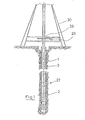
- the device according to the invention shown in FIG. 1 comprises a drilling tool 27 located in a borehole 1, which is clamped in a turntable 28 of a drilling rig 30 by means of a drill string 3 connected to its housing 2.
- the turntable 28 has a drive and blocking device 29 by means of which the chuck of the turntable 28 and thus the drill string 3 can be set in continuous rotation or aligned by a limited rotary movement and can then be fixed against rotation.
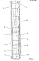
- the alternatives of the drilling tool 27 shown in FIGS. 2 to 7 have, as common features, a housing 2 consisting of several sections, in which a motor (not shown in more detail) is arranged, which e.g. can be designed as a turbine or as a displacement motor based on the Moineau principle, and its rotor is connected to a rotary drill bit 6 via an output shaft 5 mounted in a lower housing section 4.
- the housing 2 of the drilling tool 27 carries a first, central stabilizer 7 in the region of its lower housing section 4 and a second, eccentric stabilizer above the first stabilizer 7. 8th.
- the housing 2 is deflected by the support of the second, eccentric stabilizer 8 on the walls of the borehole 1, the pivot point of the deflection being based on the original borehole axis 9 in the center of gravity of the first, central stabilizer 7 lie and the rotary drill bit 6 is pressed in the opposite direction.
- the axis of rotation 10 of the output shaft 5 is thus angled relative to the original borehole axis 9.
- the first, central stabilizer 7 is preferably spherical in order to prevent its ribs from tilting against the borehole wall in the forced inclined position.
- a third, central stabilizer 11 is indicated above the housing 2, by means of whose size and placement on the drill string the straight drilling properties of the drilling tool 27 in an inclined borehole 1 can be improved.
- the second stabilizer 8 is arranged in an upper area of the housing 2. It is also possible to add it above the housing 2, but then the inclination of the axis of rotation 10 relative to the original borehole axis 9 becomes very small in relation to the eccentricity of the second stabilizer 8.
- the deflection of the drill string 3 resulting from the inclination of the housing 2 in the borehole 1 can advantageously be concentrated on a flexible section 12 which is inserted between the second stabilizer 8 and the drill string 3 lying above it Bending stresses, which would otherwise be evenly distributed over the drill string 3 and the housing 2, away from these areas and thus relieves threaded connections and bearings.
- the second stabilizer 8 is arranged closer to the first stabilizer 7.
- the lever arm causing the deflection of the axis of rotation 10 is shorter in comparison to the embodiment shown in FIG. 2, so that the required eccentricity of the second stabilizer 8 can be made smaller.
- the arrangement results in a particularly strong bending bend stress on the housing section lying between the first stabilizer 7 and the second stabilizer 8, which is designed to absorb this bending stress as a flexible section 13.
- the second stabilizer 8 is designed to be exchangeable in order to be able to freely specify the eccentricity required for the maximum desired radius of curvature of the deflection bore.
- the second stabilizer 8 can also form an integral part with the flexible section 13, which is exchanged together.
- the drive shaft forming the connection between the motor rotor and the output shaft 5 mounted in the lower housing section 4 is arranged in the flexible section 13 in the alternative according to FIG. 3.
- the cardan shaft is connected to the motor rotor and / or the output shaft 5 by a plug-in coupling in order to enable easy assembly or disassembly of the drilling tool 27 when the second stabilizer 8 is replaced.
- FIG. 4 shows a development of the embodiment according to FIG. 3, in which a further flexible section 14 is arranged above the second stabilizer 8 and the housing 2.
- This section 14 refers to the opposite of the flexible section 13 opposite bending stress, so that similarly to the flexible section 12 in Fig. 2-bending stress ⁇ be spruchungen from the housing 2 and the ohrwerk- above the B kept zeugs 27 lying train 3.
- the borehole issued the drilling tool 27 while holding the stabilizer 8 and housing 2 has a 10 white in the direction of the axis of rotation - send tolrnickten course.
- the angled axis of rotation 10 of the output shaft 5 also rotates, so that the resulting movement of the rotary drill bit 6 gives the borehole 1 a course in the direction of the original borehole axis 9.
- An optional directional drilling or G can e-radeausbohren so in a simple manner be achieved by holding or co-rotation of the second stabilizer 8 by means of the housing 2 and clamped in the rotary table 28 the drill string. 3
- the output shaft 5 can also be angled. As can be seen in FIG.
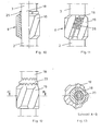
- FIGS. 7 to 11 show exemplary embodiments on the basis of an eccentrically designed, arranged in the upper region of the housing 2 second stabilizer 8.
- the second stabilizer 8 consists of a carrier body 18 and a rib sleeve 19, which can be fixed on the carrier body 18 by a positive connection. In the alternatives shown in FIGS.
- the rib sleeve 19 can be aligned in steps relative to the carrier body 18.
- the positive connection between the parts 18 and 19 is formed in the embodiment in Fig. 7 by a spline and in the Fig. 8 by a spur 21.
- FIGS. 9 to 11 allow the rib sleeve 19 to be steplessly adjusted relative to the carrier body 18 and to be fixed by a force-locking connection.
- the fixing is brought about by a shrink fit, which is brought about by hydraulically inflating the rib sleeve 19 provided with seals 22, pushing it onto the carrier body 18 and relieving the pressure of the rib sleeve 19.
- 10 shows the fixing by means of a longitudinally slotted intermediate sleeve 25, which provides the rib sleeve 19 with a conical thread area and is jammed on the carrier body 18 when it is screwed thereto 19.
- a fixation by jamming also takes place in the alternative shown in FIG. 11, in which the rib sleeve 19 is slotted along a rib and is clamped by several screws 26 in the manner of a clamp.
- a first, central stabilizer 7 could also be designed to be alignable in accordance with the alternatives explained above.
- the second stabilizer 8 can also be designed to be adjustable.
- such an embodiment is provided with an eccentric intermediate sleeve 23 in addition to the carrier body 18 and the rib sleeve 19.
- the degree of eccentricity of the stabilizer 8 can thus be between a maximum value and a minimum value in Levels are changed, the possibility of alignment with the carrier body 18 being retained.
- the parts are fixed by a spur toothing, as described in the embodiment according to FIG. 8.
- the first, central stabilizer 7 is matched to the dimension of the borehole diameter, while the second, eccentric stabilizer 8 is designed with undersize in order to prevent the housing from bending 2 and the output shaft 5 resulting inclination change tendency.
Landscapes
- Engineering & Computer Science (AREA)
- Life Sciences & Earth Sciences (AREA)
- Geology (AREA)
- Mining & Mineral Resources (AREA)
- Physics & Mathematics (AREA)
- Environmental & Geological Engineering (AREA)
- Fluid Mechanics (AREA)
- General Life Sciences & Earth Sciences (AREA)
- Geochemistry & Mineralogy (AREA)
- Mechanical Engineering (AREA)
- Earth Drilling (AREA)
Applications Claiming Priority (2)
| Application Number | Priority Date | Filing Date | Title |
|---|---|---|---|
| DE3403239A DE3403239C1 (de) | 1984-01-31 | 1984-01-31 | Vorrichtungen zum wahlweisen Geradeaus- oder Richtungsbohren in unterirdische Gesteinsformationen |
| DE3403239 | 1984-01-31 |
Publications (2)
| Publication Number | Publication Date |
|---|---|
| EP0162190A1 true EP0162190A1 (fr) | 1985-11-27 |
| EP0162190B1 EP0162190B1 (fr) | 1989-12-06 |
Family
ID=6226338
Family Applications (1)
| Application Number | Title | Priority Date | Filing Date |
|---|---|---|---|
| EP85100936A Expired EP0162190B1 (fr) | 1984-01-31 | 1985-01-30 | Dispositif pour forer des formations souterraines optionellement verticalement ou en biais |
Country Status (6)
| Country | Link |
|---|---|
| US (1) | US4610307A (fr) |
| EP (1) | EP0162190B1 (fr) |
| JP (1) | JPS60164592A (fr) |
| AU (1) | AU572621B2 (fr) |
| CA (1) | CA1236825A (fr) |
| DE (1) | DE3403239C1 (fr) |
Families Citing this family (33)
| Publication number | Priority date | Publication date | Assignee | Title |
|---|---|---|---|---|
| US4739842A (en) * | 1984-05-12 | 1988-04-26 | Eastman Christensen Company | Apparatus for optional straight or directional drilling underground formations |
| US5343967A (en) * | 1984-05-12 | 1994-09-06 | Baker Hughes Incorporated | Apparatus for optional straight or directional drilling underground formations |
| US4577701A (en) * | 1984-08-08 | 1986-03-25 | Mobil Oil Corporation | System of drilling deviated wellbores |
| US4694913A (en) * | 1986-05-16 | 1987-09-22 | Gas Research Institute | Guided earth boring tool |
| DE3804493A1 (de) * | 1988-02-12 | 1989-08-24 | Eastman Christensen Co | Vorrichtung zum wahlweisen geradeaus- oder richtungsbohren in unterirdische gesteinsformationen |
| US4877092A (en) * | 1988-04-15 | 1989-10-31 | Teleco Oilfield Services Inc. | Near bit offset stabilizer |
| FR2641315B1 (fr) * | 1988-12-30 | 1996-05-24 | Inst Francais Du Petrole | Garniture de forage a trajectoire controlee comportant un stabilisateur a geometrie variable et utilisation de cette garniture |
| FR2641316B1 (fr) * | 1988-12-30 | 1995-09-08 | Inst Francais Du Petrole | Garniture pour forage a trajectoire controlee comportant un element coude a angle variable et utilisation de cette garniture |
| DE3936362C1 (fr) * | 1989-11-02 | 1991-03-07 | Eastman Christensen Co., Salt Lake City, Utah, Us | |
| US5248004A (en) * | 1989-11-02 | 1993-09-28 | Baker Hughes Incorporated | Adjustable pipe joint |
| US5148875A (en) * | 1990-06-21 | 1992-09-22 | Baker Hughes Incorporated | Method and apparatus for horizontal drilling |
| US5074366A (en) * | 1990-06-21 | 1991-12-24 | Baker Hughes Incorporated | Method and apparatus for horizontal drilling |
| US5503236A (en) * | 1993-09-03 | 1996-04-02 | Baker Hughes Incorporated | Swivel/tilting bit crown for earth-boring drills |
| US5738178A (en) * | 1995-11-17 | 1998-04-14 | Baker Hughes Incorporated | Method and apparatus for navigational drilling with a downhole motor employing independent drill string and bottomhole assembly rotary orientation and rotation |
| US5765653A (en) * | 1996-10-09 | 1998-06-16 | Baker Hughes Incorporated | Reaming apparatus and method with enhanced stability and transition from pilot hole to enlarged bore diameter |
| US5957223A (en) * | 1997-03-05 | 1999-09-28 | Baker Hughes Incorporated | Bi-center drill bit with enhanced stabilizing features |
| US6102138A (en) * | 1997-08-20 | 2000-08-15 | Baker Hughes Incorporated | Pressure-modulation valve assembly |
| US6213226B1 (en) | 1997-12-04 | 2001-04-10 | Halliburton Energy Services, Inc. | Directional drilling assembly and method |
| US6920944B2 (en) * | 2000-06-27 | 2005-07-26 | Halliburton Energy Services, Inc. | Apparatus and method for drilling and reaming a borehole |
| US6470974B1 (en) | 1999-04-14 | 2002-10-29 | Western Well Tool, Inc. | Three-dimensional steering tool for controlled downhole extended-reach directional drilling |
| US6622803B2 (en) | 2000-03-22 | 2003-09-23 | Rotary Drilling Technology, Llc | Stabilizer for use in a drill string |
| CN101025075B (zh) * | 2006-02-21 | 2011-03-16 | 中国石油大学(北京) | 自动防斜钻井装置 |
| CN101059061B (zh) * | 2007-04-26 | 2012-10-03 | 倪红坚 | 滑动推靠式导向钻井工具 |
| FR2927936B1 (fr) * | 2008-02-21 | 2010-03-26 | Vam Drilling France | Element de garniture de forage, tige de forage et train de tiges de forage correspondant |
| CN101250982B (zh) * | 2008-04-02 | 2011-12-07 | 刘宝林 | 一种机械式自动垂直钻具 |
| NO333280B1 (no) * | 2009-05-06 | 2013-04-29 | Norwegian Hard Rock Drilling As | Styreanordning for bergboremaskin. |
| US20100326731A1 (en) * | 2009-06-25 | 2010-12-30 | Pilot Drilling Control Limited | Stabilizing downhole tool |
| US8851205B1 (en) * | 2011-04-08 | 2014-10-07 | Hard Rock Solutions, Llc | Method and apparatus for reaming well bore surfaces nearer the center of drift |
| US20150050083A1 (en) * | 2013-08-15 | 2015-02-19 | Smith International, Inc. | Locking ring with stabilizing blades |
| US9151119B1 (en) * | 2014-05-23 | 2015-10-06 | Alaskan Energy Resources, Inc. | Bidirectional dual eccentric reamer |
| US9316056B1 (en) | 2014-05-23 | 2016-04-19 | Alaskan Energy Resources, Inc. | Drilling rig with bidirectional dual eccentric reamer |
| CA3075388A1 (fr) | 2017-09-09 | 2019-03-14 | Extreme Technologies, Llc | Conditionneur et stabilisateur de puits de forage |
| CN111465746B (zh) | 2017-10-10 | 2022-09-06 | 高级技术有限责任公司 | 井眼铰孔系统和装置 |
Citations (6)
| Publication number | Priority date | Publication date | Assignee | Title |
|---|---|---|---|---|
| GB636879A (en) * | 1946-07-12 | 1950-05-10 | Rolen Arcenjevitch Joannesjan | Improvements in or relating to the drilling of deep wells |
| US3260318A (en) * | 1963-11-12 | 1966-07-12 | Smith Ind International Inc | Well drilling apparatus |
| GB1483789A (en) * | 1974-11-07 | 1977-08-24 | Amoco Prod Co | Drilling tool for the directional drilling of boreholes in the earth |
| US4185704A (en) * | 1978-05-03 | 1980-01-29 | Maurer Engineering Inc. | Directional drilling apparatus |
| US4227584A (en) * | 1978-12-19 | 1980-10-14 | Driver W B | Downhole flexible drive system |
| EP0085444A2 (fr) * | 1982-02-02 | 1983-08-10 | Shell Internationale Researchmaatschappij B.V. | Procédé et dispositif pour contrôler la direction d'un trou de forage |
Family Cites Families (7)
| Publication number | Priority date | Publication date | Assignee | Title |
|---|---|---|---|---|
| US2829864A (en) * | 1955-02-01 | 1958-04-08 | Seth R Knapp | Method and apparatus for straightening well bore holes |
| US3135103A (en) * | 1962-04-27 | 1964-06-02 | Black Harold | Flexible joint for drill string |
| GB1212915A (en) * | 1968-01-19 | 1970-11-18 | Rolls Royce | Apparatus for bore-hole drilling |
| GB1388713A (en) * | 1972-03-24 | 1975-03-26 | Russell M K | Directional drilling of boreholes |
| US3730286A (en) * | 1972-06-29 | 1973-05-01 | Exxon Production Research Co | Apparatus for improving rotary drilling operations |
| US4319649A (en) * | 1973-06-18 | 1982-03-16 | Jeter John D | Stabilizer |
| US3938853A (en) * | 1974-05-01 | 1976-02-17 | Christensen Diamond Products Company | Shrink-fit sleeve apparatus for drill strings |
-
1984
- 1984-01-31 DE DE3403239A patent/DE3403239C1/de not_active Expired
-
1985
- 1985-01-18 AU AU37771/85A patent/AU572621B2/en not_active Ceased
- 1985-01-25 JP JP60011120A patent/JPS60164592A/ja active Pending
- 1985-01-30 CA CA000473135A patent/CA1236825A/fr not_active Expired
- 1985-01-30 EP EP85100936A patent/EP0162190B1/fr not_active Expired
- 1985-12-18 US US06/810,895 patent/US4610307A/en not_active Expired - Fee Related
Patent Citations (6)
| Publication number | Priority date | Publication date | Assignee | Title |
|---|---|---|---|---|
| GB636879A (en) * | 1946-07-12 | 1950-05-10 | Rolen Arcenjevitch Joannesjan | Improvements in or relating to the drilling of deep wells |
| US3260318A (en) * | 1963-11-12 | 1966-07-12 | Smith Ind International Inc | Well drilling apparatus |
| GB1483789A (en) * | 1974-11-07 | 1977-08-24 | Amoco Prod Co | Drilling tool for the directional drilling of boreholes in the earth |
| US4185704A (en) * | 1978-05-03 | 1980-01-29 | Maurer Engineering Inc. | Directional drilling apparatus |
| US4227584A (en) * | 1978-12-19 | 1980-10-14 | Driver W B | Downhole flexible drive system |
| EP0085444A2 (fr) * | 1982-02-02 | 1983-08-10 | Shell Internationale Researchmaatschappij B.V. | Procédé et dispositif pour contrôler la direction d'un trou de forage |
Also Published As
| Publication number | Publication date |
|---|---|
| DE3403239C1 (de) | 1985-06-27 |
| AU3777185A (en) | 1985-08-08 |
| EP0162190B1 (fr) | 1989-12-06 |
| US4610307A (en) | 1986-09-09 |
| JPS60164592A (ja) | 1985-08-27 |
| AU572621B2 (en) | 1988-05-12 |
| CA1236825A (fr) | 1988-05-17 |
Similar Documents
| Publication | Publication Date | Title |
|---|---|---|
| EP0162190A1 (fr) | Dispositif pour forer des formations souterraines optionellement verticalement ou en biais | |
| DE3234552C2 (de) | Vorrichtung zum Herstellen eines Gesteinsbohrlochs | |
| DE60308993T2 (de) | Sondengehäuse und verfahren zur herstellung | |
| EP0044386B1 (fr) | Dispositif de perçage en vue de percer un trou présentant une partie détalonnée | |
| DE3876127T2 (de) | Einrichtung zum richtbohren von bohrloechern. | |
| EP0425782B1 (fr) | Connexion de tubes pour train de forage | |
| EP1213081B1 (fr) | Outil pour usinage de précision par enlèvement de copeaux | |
| DE3206387A1 (de) | Bohrwerkzeug fuer hinterschnittene bohrungen | |
| EP0327925B1 (fr) | Appareil pour le forage optionnellement droit ou dirigé dans des formations souterraines | |
| EP0351699A2 (fr) | Trépan carottier | |
| EP0698436A1 (fr) | Dispositif de forage à fabriquer des trous avec chambrage | |
| DE3310147A1 (de) | Bohrfutter fuer schlagbohrbetrieb | |
| DE3809761A1 (de) | Hinterschnitt-bohrvorrichtung | |
| DE3428481C1 (de) | Werkzeughalter mit Radialverstellvorrichtung fuer ein Werkzeug,insbesondere ein Ausdrehwerkzeug | |
| DE3423465C1 (de) | Vorrichtungen zum wahlweisen Geradeaus- oder Richtungsbohren in unterirdische Gesteinsformationen | |
| EP0474591A2 (fr) | Tige encastrée avec prise centrale d'un foret | |
| EP0258660A1 (fr) | Fleuret plein à une lèvre de coupe | |
| DE3417743C1 (de) | Vorrichtung zum wahlweisen Geradeaus- oder Richtungsbohren in unterirdische Gesteinsformationen | |
| EP0038917B1 (fr) | Unité de perçage destinée à fabriquer des trous | |
| EP0778390B1 (fr) | Perceuse rotative hélicoidale à percussion | |
| WO1992004523A1 (fr) | Table de perçage | |
| DD296634A5 (de) | Vorrichtung zur herstellung einer hinterschneidung in einem bohrloch | |
| DE2436501B2 (de) | Bohrstange | |
| EP0563950A1 (fr) | Appareil et procédé pour le forage dirigé | |
| DE19954315A1 (de) | Bohrwerkzeug |
Legal Events
| Date | Code | Title | Description |
|---|---|---|---|
| PUAI | Public reference made under article 153(3) epc to a published international application that has entered the european phase |
Free format text: ORIGINAL CODE: 0009012 |
|
| AK | Designated contracting states |
Designated state(s): BE FR GB NL |
|
| 17P | Request for examination filed |
Effective date: 19860307 |
|
| 17Q | First examination report despatched |
Effective date: 19870319 |
|
| RAP1 | Party data changed (applicant data changed or rights of an application transferred) |
Owner name: EASTMAN CHRISTENSEN COMPANY |
|
| GRAA | (expected) grant |
Free format text: ORIGINAL CODE: 0009210 |
|
| AK | Designated contracting states |
Kind code of ref document: B1 Designated state(s): BE FR GB NL |
|
| ET | Fr: translation filed | ||
| GBT | Gb: translation of ep patent filed (gb section 77(6)(a)/1977) | ||
| PLBE | No opposition filed within time limit |
Free format text: ORIGINAL CODE: 0009261 |
|
| STAA | Information on the status of an ep patent application or granted ep patent |
Free format text: STATUS: NO OPPOSITION FILED WITHIN TIME LIMIT |
|
| 26N | No opposition filed | ||
| PGFP | Annual fee paid to national office [announced via postgrant information from national office to epo] |
Ref country code: BE Payment date: 19931222 Year of fee payment: 10 |
|
| PG25 | Lapsed in a contracting state [announced via postgrant information from national office to epo] |
Ref country code: BE Effective date: 19950131 |
|
| BERE | Be: lapsed |
Owner name: EASTMAN CHRISTENSEN CY Effective date: 19950131 |
|
| PGFP | Annual fee paid to national office [announced via postgrant information from national office to epo] |
Ref country code: FR Payment date: 19971218 Year of fee payment: 14 |
|
| PGFP | Annual fee paid to national office [announced via postgrant information from national office to epo] |
Ref country code: NL Payment date: 19971222 Year of fee payment: 14 |
|
| PGFP | Annual fee paid to national office [announced via postgrant information from national office to epo] |
Ref country code: GB Payment date: 19971223 Year of fee payment: 14 |
|
| PG25 | Lapsed in a contracting state [announced via postgrant information from national office to epo] |
Ref country code: GB Free format text: LAPSE BECAUSE OF NON-PAYMENT OF DUE FEES Effective date: 19990130 |
|
| PG25 | Lapsed in a contracting state [announced via postgrant information from national office to epo] |
Ref country code: NL Free format text: LAPSE BECAUSE OF NON-PAYMENT OF DUE FEES Effective date: 19990801 |
|
| GBPC | Gb: european patent ceased through non-payment of renewal fee |
Effective date: 19990130 |
|
| PG25 | Lapsed in a contracting state [announced via postgrant information from national office to epo] |
Ref country code: FR Free format text: LAPSE BECAUSE OF NON-PAYMENT OF DUE FEES Effective date: 19990930 |
|
| REG | Reference to a national code |
Ref country code: FR Ref legal event code: ST |