EP0162286A1 - Steuerventil - Google Patents
Steuerventil Download PDFInfo
- Publication number
- EP0162286A1 EP0162286A1 EP85104652A EP85104652A EP0162286A1 EP 0162286 A1 EP0162286 A1 EP 0162286A1 EP 85104652 A EP85104652 A EP 85104652A EP 85104652 A EP85104652 A EP 85104652A EP 0162286 A1 EP0162286 A1 EP 0162286A1
- Authority
- EP
- European Patent Office
- Prior art keywords
- valve
- bore
- spindle
- valve body
- section
- Prior art date
- Legal status (The legal status is an assumption and is not a legal conclusion. Google has not performed a legal analysis and makes no representation as to the accuracy of the status listed.)
- Withdrawn
Links
- 239000004033 plastic Substances 0.000 claims description 5
- 238000009423 ventilation Methods 0.000 claims 1
- 230000006835 compression Effects 0.000 description 7
- 238000007906 compression Methods 0.000 description 7
- 238000007789 sealing Methods 0.000 description 2
- 238000011109 contamination Methods 0.000 description 1
- 238000013016 damping Methods 0.000 description 1
- 238000011161 development Methods 0.000 description 1
- 230000018109 developmental process Effects 0.000 description 1
- 238000002347 injection Methods 0.000 description 1
- 239000007924 injection Substances 0.000 description 1
Images
Classifications
-
- F—MECHANICAL ENGINEERING; LIGHTING; HEATING; WEAPONS; BLASTING
- F16—ENGINEERING ELEMENTS AND UNITS; GENERAL MEASURES FOR PRODUCING AND MAINTAINING EFFECTIVE FUNCTIONING OF MACHINES OR INSTALLATIONS; THERMAL INSULATION IN GENERAL
- F16K—VALVES; TAPS; COCKS; ACTUATING-FLOATS; DEVICES FOR VENTING OR AERATING
- F16K11/00—Multiple-way valves, e.g. mixing valves; Pipe fittings incorporating such valves
- F16K11/02—Multiple-way valves, e.g. mixing valves; Pipe fittings incorporating such valves with all movable sealing faces moving as one unit
- F16K11/04—Multiple-way valves, e.g. mixing valves; Pipe fittings incorporating such valves with all movable sealing faces moving as one unit comprising only lift valves
- F16K11/048—Multiple-way valves, e.g. mixing valves; Pipe fittings incorporating such valves with all movable sealing faces moving as one unit comprising only lift valves with valve seats positioned between movable valve members
-
- F—MECHANICAL ENGINEERING; LIGHTING; HEATING; WEAPONS; BLASTING
- F16—ENGINEERING ELEMENTS AND UNITS; GENERAL MEASURES FOR PRODUCING AND MAINTAINING EFFECTIVE FUNCTIONING OF MACHINES OR INSTALLATIONS; THERMAL INSULATION IN GENERAL
- F16K—VALVES; TAPS; COCKS; ACTUATING-FLOATS; DEVICES FOR VENTING OR AERATING
- F16K31/00—Actuating devices; Operating means; Releasing devices
- F16K31/12—Actuating devices; Operating means; Releasing devices actuated by fluid
- F16K31/42—Actuating devices; Operating means; Releasing devices actuated by fluid by means of electrically-actuated members in the supply or discharge conduits of the fluid motor
- F16K31/423—Actuating devices; Operating means; Releasing devices actuated by fluid by means of electrically-actuated members in the supply or discharge conduits of the fluid motor the actuated members consisting of multiple way valves
Definitions
- the invention relates to a control valve according to the preamble of the main claim.
- the valve body is fixed to the control element.
- the control valve is complex.
- the assembly of the control element in the control valve is complicated.
- the control valve according to the invention with the characterizing features of the main claim has the advantage that the assembly is simple and cheap. If one of the two valve bodies reaches its valve seat, no great impact forces act on the valve seat and thus on the valve housing. The control can be controlled damped. One of the two valve bodies both opens its facing valve seat and controls the opening of the vent hole at the same time.
- the valve housing including valve seats can be manufactured in one operation.
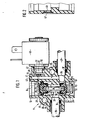
- FIG. 1 shows a longitudinal section through a control valve and Figure 2 shows a section through a detail.
- a continuous step opening 12 is formed, which is closed on both sides by closure parts 13, 1 4 .
- Both closure parts 13, 14 are pressed into the stepped bore 12.
- This has an approximately central section 16 with the smallest diameter.
- Sections 17, 18 of the stepped bore 12 arranged on both sides of this section 16 have approximately the same diameter and serve as pressure chambers.
- the shoulder formed between sections 16 and 17 forms a valve seat 19 for a valve body 20 which is slidably guided in section 17. It is made of plastic and has an outer layer 22 made of rubber.
- the valve body 20 has a central recess 23 facing the section 16.
- One end 24 of a spindle 25 plunges into this with play.
- the shoulder formed between the sections 16 and 18 of the stepped bore 12 serves as a valve seat 27 for a second valve body 28 which is slidably guided in the section 18. It is also made of plastic and has an outer Layer 29 of rubber. It also has a central recess 30 facing section 16, into which the other end 31 of the spindle 25 dips with play. On the side of the valve body 28 facing away from the section 16 of the stepped bore 12, one end of a compression spring 32 arranged in the section 18 of the stepped bore 12 lies, the other end of which rests on the closure part 13. The axes of the spindle 25, the two valve bodies 20, 28 and the stepped bore 12 are congruent.
- the housing 10 is also made of plastic, the two valve seats 19, 27 being injection molded in one operation and no aftertreatment is necessary.
- a transverse bore 33 opens into which a tubular consumer connection 35 sealed by a sealing ring 34 is arranged.
- a transverse bore 36 opens into section 18 of the stepped bore 12, into which a tubular pump connection 37 is inserted. It is sealed by a sealing ring 38.
- a bore 39 runs parallel to the stepped bore 12 in front of the pump connection 37 and is closed at its end by a closure part 40.
- a transverse bore 41 leads to a recess 42 which is closed by an electromagnet 43 flanged to the housing 10.
- the opening of the transverse bore 41 in the recess 42 is designed as a valve seat 44.
- a transverse bore 45 leads from the recess 42 into the section 17 of the stepped bore 12. It is formed in a second plane in the housing 10 and opens near the closure part 14. From the section 17 of the stepped bore 12, a passage 46 leads into the open near the valve seat 19, in which - as shown in more detail in FIG. 2 - a filter screen 47 protecting against contamination is arranged.
- the plunger 48 of the electric magnet 43 protrudes into the recess 42 and rests on the valve seat 44 with the end face of its outer collar 49.
- One end of a compression spring 50 bears against the other side of the collar 49, the other end of which rests on a lens 51 fixedly arranged in the recess 42.
- the electromagnet 43 If the electromagnet 43 is de-energized, the end face of the tappet 48 rests on the valve seat 44 due to the force of the compression spring 50.
- the section 17 of the stepped bore 12 is vented to the outside via the passage 46 and the filter sieve 47.
- the valve body 20 is relieved of pressure and the valve body 28 rests on its valve seat 27 by the force of the compression spring 32. Since the end of the spindle 25 is arranged with play in the recess 30 of the valve body 28, the valve body 28 only hits the valve seat 27 with its own small mass. The spindle 25 and the valve body 20 continue to move due to the inertial force.
- the length of the section 17 of the stepped bore 12 is designed such that the valve body 20 does not strike the closure part 14 before the valve body 28 rests on its valve seat 27.
- a damping body or a spring on the closure part 14 in order to largely avoid impacts on the valve housing 10. In this position, the consumer connection 35 is relieved into the open via the transverse bore 33, the opened valve seat 19 and the transverse bore 46.
- the electromagnet 43 If the electromagnet 43 is energized, its plunger 48 moves in counter to the force of the compression spring 50 and the valve seat 44 is open.
- the flowing in via the pump connection 37 in the transverse bore 36 and in the bore 39 pressure medium flows through the transverse bore 40 and the geöff Neten valve seat 44 into the recess 42 and further via the transverse bore 45 in the uppermost part of section 17 of the stepped bore 12.
- a pressure builds up, which presses the valve body 20 onto its valve seat 19.
- the transverse bore 46 is also closed by the valve body 20.
- the valve body 28 With the aid of the spindle 25, however, the valve body 28 is also lifted from its valve seat 27 against the force of the compression spring 32 by the pressure acting on the valve body 20.
- the pressure medium can now also flow from the transverse bore 36 via the open valve seat 27 into the transverse bore 33 and into the consumer connection 35.
- the inventive arrangement of the spindle 25 and the two valve bodies 20, 28 enables easy assembly.
- the spindle 25 can be easily inserted into the section 16 from both sides of the stepped bore 12.
- the two valve bodies 20, 28 are inserted from both sides into the stepped bore 12 and placed on the ends 24, 31 of the spindle 25. After the compression spring 32 is arranged in section 18, the two closure parts 13, 14 are pressed into the stepped bore 12.
Landscapes
- Engineering & Computer Science (AREA)
- General Engineering & Computer Science (AREA)
- Mechanical Engineering (AREA)
- Magnetically Actuated Valves (AREA)
Abstract
in einem 3 2-Magnetventil (11) ist eine Stufenbohrung (12) ausgebildet, in deren mittleren Abschnitt (16) mit kleinstern Durchmesser eine Spindel (25) angeordnet ist. Seine beiaen Enden (24, 31; ragen mit Spiel in je eine Ausnehmung (23 bzw. (30) eines Ventilkörpers (20) bzw. (28). Diese sind den am Abschnitt (16) der Stufenbohrung (121 ausgebildeten Ventilsitzen (19, 27) zugeordnet. Da die Ventilkörper (20, 28) lose an der Spindel (25) angeordnet sind, schlagen die Ventilkörper (20. 28) nur mit ihrer eigenen, geringen Masse am jeweiligen Ventilsitz (19, 27) auf. Die Montage der Spinde (25) und der Ventilkörper (20, 28) in der Stufenbohrung (12) ist dadurch einfach.
Description
- Die Erfindung geht aus von einem Steuerventil nach der Gattung des Hauptanspruchs. Bei einem derartigen bekannten Steuerventil sind die Ventilkörper fest am Steuerelement angeordnet. Dadurch baut das Steuerventil aufwendig. Die Montage des Steuerelements im Steuerventil ist kompliziert.
- Das erfindungsgemäße Steuerventil mit den kennzeichnenden Merkmalen des Hauptanspruchs hat demgegenüber den Vorteil, daß die Montage einfach und billig ist. Gelangt einer der beiden Ventilkörper auf seinen Ventilsitz, so wirken keine großen Schlagkräfte auf den Ventilsitz und somit auf das Ventilgehäuse ein. Das Steuerelement ist gedämpft steuerbar. Einer der beiden Ventilkörper öffnet sowohl seinen zugewandten Ventilsitz, als auch steuert er zugleich die Öffnung der Entlüftungsbohrung. Das Ventilghäuse samt Ventilsitze ist in einem Arbeitsgang herstellbar.
- Durch die in den Unteransprüchen aufgeführten Maßnahmen sind vorteilhafte Weiterbildungen und Verbesserungen der im Hauptanspruch angegebenen Merkmale möglich.
- Ein Ausfübrungsbeispiel der Erfindung i.st in der Zeichnung dargestellt und in der nachfolgenden Beschreibung näher erläutert. Es zeigen Figur 1 einen Längsschnitt durch ein Steuerventil und Figur 2 einen Schnitt durch eine Einzelheit.
- Beschreibung des Ausführungsbeispiels
- In einer Gehäuse 1C eines 3/2-Magnetventils 11, das als Druckluftventil eingesetzt ist, ist eine durchgehende Stufenbchrung 12 ausgebildet, die auf beiden Seiten von Verschlußteilen 13, 14 verschlossen ist. Beide Verschlußteile 13, 14 sind in die Stufenbohrung 12 eingepreßt. Diese weist einen etwa mittigen Abschnitt 16 mit kleinstem Durchmesser auf Die zu beiden Seiten dieses Abschnitts 16 angeordneten Abschnitte 17, 18 der Stufenbohrung 12 haben etwa gleichen Durchmesser und dienen als Druckräume. Die zwischer den Abschnitten 16 und 17 gebildete Schulter bildet einen Ventilsitz 19 für einen Ventilkörper 20, der gleitend im Abschnitt 17 geführt ist. Er ist aus Kunststoff hergestellt und hat eine äußere Schicht 22 aus Gummi. Der Ventilkörper 20 weist eine mittige, dem Abschnitt 16 zugewandte Ausnehmung 23 auf. In diese taucht das eine Ende 24 einer Spindel 25 mit Spiel ein.
- Die zwischen den Abschnitten 16 und 18 der Stufenbohrung 12 ausgebildete Schulter dient als Ventilsitz 27 für einen zweiten Ventilkörper 28, der im Abschnitt 18 gleitend geführt ist. Er besteht ebenfalls aus Kunststoff und hat eine äußere Schicht 29 aus Gummi. Er hat ferner eine mittige, dem Abschnitt 16 zugewandte Ausnehmung 30, in die das andere Ende 31 der Spindel 25 mit Spiel eintaucht. An die dem Abschnitt 16 der Stufenbohrung 12 abgewandte Seite des Ventilkörpers 28 legt sich das eine Ende einer im Abschnitt 18 der Stufehbohung 12 angeordneten Druckfeder 32 an, deren anderes Ende am Verschlußteil 13 anliegt. Die Achsen der Spindel 25, der beiden Ventilkörper 20, 28 und der Stufenbohrung 12 sind deckungsgleich. Das Gehäuse 10 besteht auch aus Kunststoff, wobei die beiden Ventilsitze 19, 27 in einem Arbeitsgang angespritzt sind und keine Nachbehandlung notwendig ist.
- Im Abschnitt 16 der Stufenbohrung 12 mündet eine Querbohrung 33, in der ein durch einen Dichtring 34 abgedichteter rohrförmiger Verbraucheranschluß 35 angeordnet ist. Nahe dem Ventilsitz 27 mündet in den Abschnitt 18 der Stufenbohrung 12 eine Querbohrung 36, in die ein rohrförmiger Pumpenanschluß 37 eingesetzt ist. Er ist durch einen Dichtring 38 abgedichtet. Von der Querbohrung 36 zweigt vor dem Pumpenanschluß 37 eine parallel zur Stufenbohrung 12 verlaufende Bohrung 39 ab, die an ihrem Ende von einem Verschlußteil 40 verschlossen ist. Von dieser führt eine Querbohrung 41 zu einer Ausnehmung 42, die durch einen am Gehäuse 10 angeflanschten Elektromagneten 43 verschlossen ist. Die Mündung der Querbohrung 41 in die Ausnehmung 42 ist als Ventilsitz 44 ausgebildet. Von der Ausnehmung 42 führt eine Querbohrung 45 in den Abschnitt 17 der Stufenbohrung 12. Sie ist in einer zweiten Ebene im Gehäuse 10 ausgebildet und mündet nahe dem Verschlußteil 14. Vom Abschnitt 17 der Stufenbohrung 12 führt nahe dem Ventilsitz 19 ein Durchgang 46 ins Freie, in der - wie in Figur 2 näher gezeigt - ein vor Verschmutzung schützendes Filtersieb 47 angeordnet ist.
- In die Ausnehmung 42 ragt der Stößel 48 des Elektromagrieten 43 und liegt mit der Stirnseite seines äußeren Bundes 49 auf dem Ventilsitz 44 auf. An die andere Seite des Bundes 49 legt sich das eine Ende einer Druckfeder 50 an, die mit ihrem anderen Ende an einer fest in der Ausnehmung 42 angeordeten Seheibe 51 anliegt.
- Ist der Elektromagnet 43 entregt, so liegt der Stößel 48 durch die Kraft der Druckfeder 50 mit seiner Stirnseite auf dem Ventilsitz 44 auf. Der Abschnitt 17 der Stufenbohrung 12 ist über den Durchgang 46 und das Filtersieb 47 ins Freie entlüftet. Der Ventilkörper 20 ist druckentlastet und der Ventilkörper 28 liegt durch die Kraft der Druckfeder 32 auf seinem Ventilsitz 27 auf. Da das Ende der Spindel 25 mit Spiel in der Ausnehmung 30 des Ventilkörpers 28 angeordnet ist, schlägt der Ventilkörper 28 nur mit seiner eigenen geringen Masse auf den Ventilsitz 27 auf. Die Spindel 25 und der Ventilkörper 20 bewegen sich durch die Trägheitskraft weiter. Die Länge des Abschnitts 17 der Stufenbohrung 12 ist so ausgelegt, daß der Ventilkörper 20 nicht am Verschlußteil 14 anschlägt bevor der Ventilkörper 28 auf seinem Ventilsitz 27 aufliegt. Es wäre aber auch möglich, am Verschlußteil 14 einen Dämpfungskörper oder eine Feder anzuordnen, um Schläge auf das Ventilgehäuse 10 weitgehend zu vermeiden. Der Verbraucheranschluß 35 ist in dieser Stellung über die Querbohrung 33, den geöffneten Ventilsitz 19 und die Querbohrung 46 ins Freie entlastet.
- Wird der Elektromagnet 43 erregt, so fährt sein Stößel 48 entgegen der Kraft der Druckfeder 50 ein, und der Ventilsitz 44 ist geöffnet. Das über den Pumpenanschluß 37 in die Querbohrung 36 und in die Bohrung 39 einströmende Druckmittel fließt über die Querbohrung 40 und den geöffneten Ventilsitz 44 in die Ausnehmung 42 und weiter über die Querbohrung 45 in den obersten Teil des Abschnitts 17 der Stufenbohrung 12. Hier baut sich ein Druck auf, der den Ventilkörper 20 auf seinen Ventilsitz 19 drückt. Gleichzeitig wird durch den Ventilkörper 20 auch die Querbohrung 46 verschlossen. Mit Hilfe der Spindel 25 wird aber auch vom auf den Ventilkörper 20 einwirkenden Druck der Ventilkörper 28 entgegen der Kraft der Druckfeder 32 von seinem Ventilsitz 27 abgehoben. Das Druckmittel kann jetzt auch von der Querbohrung 36 über den geöffneten Ventilsitz 27 in die Querbohrung 33 und in den Verbraucheranschluß 35 strömen.
- Durch die erfindungsgemäße Anordnung der Spindel 25 und der beiden Ventilkörper 20, 28 ist eine leichte Montage möglich. Die Spindel 25 kann leicht von beiden Seiten der Stufenbohrung 12 aus in den Abschnitt 16 eingeschoben werden. Die beiden Ventilkörper 20, 28 werden von beiden Seiten in die Stufenbohrung 12 eingeführt und auf die Enden 24, 31 der Spindel 25 aufgesetzt. Nachdem die Druckfeder 32 im Abschnitt 18 angeordnet ist, werden die beiden Verschlußteile 13, 14 in die Stufenbohrung 12 eingepreßt.
Claims (7)
1. Steuerventil (11), insbesondere für Druckluftbetrieb, mit einer Bohrung (12), in der ein Steuerelement angeordnet ist, das wahlweise Druckmittel von einem Pumpenanschlus (37) zu einem Verbraucberanschluß (35) oder vom Verbraucheranschluf (35) zu einer Entlüftungsbohrung (36) steuert, dadurch gekennzeichnet, daß das Steuerelement eine Spindel (25) aufweist, an deren Enden (24, 31) je ein Ventilkörper (20, 28) lose angeordnet ist.
2. Ventil nach Anspruch 1, dadurch gekennzeichnet, daß die Bohrung als Stufenbohrung (12) ausgebildet ist und daß diese einen mittleren Abschnitt (16) mit kleinstem Durchmesser aufweist, an dem zwei den Ventilkörpern (20, 28) zugewandte Ventilsitze (19, 27) angeordnet sind.
3. Ventil nach Anspruch 1 und/oder 2, dadurch gekennzeichnet, daß mindestens einer der Ventilkörper (20) in der Stufenbohrung (12) gleitend geführt und druckbeaufschlagbar ist.
4. Ventil nach einem der Ansprüche 1 bis 3, dadurch gekennzeichnet, daß am Ventilgehäuse (10) des Steuerventils (11) ein Elektromagnet (43) angeflanscht ist, dessen Stößel (48) eine Verbindung vom Pumpenanschluß (37) zum druckbeaufschlagbaren Ventilkörper (20) steuert.
5. Ventil nach einem der Ansprüche 1 bis 4, dadurch gekennzeichnet, daß die Ventilkörper (20, 28) aus Kunststoff bestehen und von einer Schicht (22, 29) aus Gummi umhüllt sind.
6. Ventil nach einem der Ansprüche 1 bis 5, dadurch gekennzeichnet, daß das Ventilgehäuse (10) aus Kunststoff besteht.
7. Ventil nach einem der Ansprüche 1 bis 6, dadurch gekennzeichnet, daß in der Entlüftungsbohrung (46) ein Filter (47) angeordnet ist.
Applications Claiming Priority (2)
| Application Number | Priority Date | Filing Date | Title |
|---|---|---|---|
| DE19843418933 DE3418933A1 (de) | 1984-05-22 | 1984-05-22 | Steuerventil |
| DE3418933 | 1984-05-22 |
Publications (1)
| Publication Number | Publication Date |
|---|---|
| EP0162286A1 true EP0162286A1 (de) | 1985-11-27 |
Family
ID=6236475
Family Applications (1)
| Application Number | Title | Priority Date | Filing Date |
|---|---|---|---|
| EP85104652A Withdrawn EP0162286A1 (de) | 1984-05-22 | 1985-04-17 | Steuerventil |
Country Status (2)
| Country | Link |
|---|---|
| EP (1) | EP0162286A1 (de) |
| DE (1) | DE3418933A1 (de) |
Cited By (4)
| Publication number | Priority date | Publication date | Assignee | Title |
|---|---|---|---|---|
| EP0620198A3 (de) * | 1993-04-15 | 1996-02-28 | Emhart Glass Mach Invest | Ventilblock-Konstruktion für I.S. Maschinen. |
| EP0620197A3 (de) * | 1993-04-15 | 1996-02-28 | Emhart Glass Mach Invest | Ventilblock-Konstruktion für I.S. Maschinen. |
| EP0675083A3 (de) * | 1994-03-31 | 1996-02-28 | Emhart Glass Mach Invest | Ventilblock für I.S. Maschinen. |
| WO2017102270A1 (de) * | 2015-12-16 | 2017-06-22 | Eto Magnetic Gmbh | Elektromagnetische ventilvorrichtung und verwendung einer solchen |
Families Citing this family (1)
| Publication number | Priority date | Publication date | Assignee | Title |
|---|---|---|---|---|
| DE10222936A1 (de) * | 2002-05-24 | 2003-12-04 | Zahnradfabrik Friedrichshafen | Proportional-Druckregelventil |
Citations (5)
| Publication number | Priority date | Publication date | Assignee | Title |
|---|---|---|---|---|
| US2307671A (en) * | 1941-09-20 | 1943-01-05 | Gen Tire & Rubber Co | Piston for fluid actuated devices |
| US2408883A (en) * | 1942-10-01 | 1946-10-08 | Bliss E W Co | Solenoid controlled valve |
| US2611391A (en) * | 1945-12-14 | 1952-09-23 | Ross Operating Valve Co | Valve |
| DE1450615A1 (de) * | 1964-04-23 | 1969-05-22 | Nostorag Ag | Elektromagnetisches Ventil |
| DE2055972A1 (de) * | 1969-11-26 | 1971-05-27 | Sahlin Eng Co Inc | Ventilkorper zur Durchflußsteuerung von Hochdruckluft |
-
1984
- 1984-05-22 DE DE19843418933 patent/DE3418933A1/de not_active Withdrawn
-
1985
- 1985-04-17 EP EP85104652A patent/EP0162286A1/de not_active Withdrawn
Patent Citations (5)
| Publication number | Priority date | Publication date | Assignee | Title |
|---|---|---|---|---|
| US2307671A (en) * | 1941-09-20 | 1943-01-05 | Gen Tire & Rubber Co | Piston for fluid actuated devices |
| US2408883A (en) * | 1942-10-01 | 1946-10-08 | Bliss E W Co | Solenoid controlled valve |
| US2611391A (en) * | 1945-12-14 | 1952-09-23 | Ross Operating Valve Co | Valve |
| DE1450615A1 (de) * | 1964-04-23 | 1969-05-22 | Nostorag Ag | Elektromagnetisches Ventil |
| DE2055972A1 (de) * | 1969-11-26 | 1971-05-27 | Sahlin Eng Co Inc | Ventilkorper zur Durchflußsteuerung von Hochdruckluft |
Cited By (8)
| Publication number | Priority date | Publication date | Assignee | Title |
|---|---|---|---|---|
| EP0620198A3 (de) * | 1993-04-15 | 1996-02-28 | Emhart Glass Mach Invest | Ventilblock-Konstruktion für I.S. Maschinen. |
| EP0620197A3 (de) * | 1993-04-15 | 1996-02-28 | Emhart Glass Mach Invest | Ventilblock-Konstruktion für I.S. Maschinen. |
| EP0675083A3 (de) * | 1994-03-31 | 1996-02-28 | Emhart Glass Mach Invest | Ventilblock für I.S. Maschinen. |
| WO2017102270A1 (de) * | 2015-12-16 | 2017-06-22 | Eto Magnetic Gmbh | Elektromagnetische ventilvorrichtung und verwendung einer solchen |
| EP3628901A1 (de) * | 2015-12-16 | 2020-04-01 | ETO MAGNETIC GmbH | Elektromagnetische ventilvorrichtung und verwendung einer solchen |
| CN111503314A (zh) * | 2015-12-16 | 2020-08-07 | Eto电磁有限责任公司 | 电磁式阀门装置和其应用 |
| US10767769B2 (en) | 2015-12-16 | 2020-09-08 | Eto Magnetic Gmbh | Electromagnetic valve device and use thereof |
| US11560955B2 (en) | 2015-12-16 | 2023-01-24 | Eto Magnetic Gmbh | Electromagnetic valve device and use thereof |
Also Published As
| Publication number | Publication date |
|---|---|
| DE3418933A1 (de) | 1985-11-28 |
Similar Documents
| Publication | Publication Date | Title |
|---|---|---|
| DE3802648C2 (de) | ||
| DE2315425A1 (de) | Elektromagnetisch betaetigtes wegeventil | |
| DE2110596B2 (de) | Magnetventil | |
| DE1943693B2 (de) | Federbelastetes rueckschlagventil | |
| DE3922155A1 (de) | Magnetventil | |
| DE4239160C1 (de) | Regelbarer hydraulischer Schwingungsdämpfer für Kraftfahrzeuge | |
| DE2744917A1 (de) | Sitzventil mit geradem durchgang | |
| DE3804100A1 (de) | Elektromagnetisches ventil zur durchflusssteuerung insbesondere zur drucksteuerung | |
| DE8626681U1 (de) | Elektromagnetventil | |
| DE2705303A1 (de) | Rueckschlagventil mit zusaetzlicher betaetigung | |
| CH643042A5 (en) | Solenoid valve arrangement | |
| DE2701580A1 (de) | Druckventil | |
| DE3418933A1 (de) | Steuerventil | |
| DE3310785C2 (de) | ||
| DE3106578C2 (de) | Doppelsitzventil mit Leckkontrolle | |
| DE4120292C2 (de) | Durch einen Elektromagneten betätigbares Doppelsitz-Ventil | |
| DE2003739A1 (de) | Ventil mit einer einen Ventilkoerper aufnehmenden Ventilkammer | |
| DE2716694A1 (de) | Steuereinrichtung fuer einen hydraulischen arbeitszylinder | |
| DE3415923A1 (de) | Wegeventil | |
| DE8806867U1 (de) | Elektromagnetisch betätigbares 5/2-Wegeventil | |
| DE9314210U1 (de) | Rückschlagventil | |
| DE3705082A1 (de) | Magnetventil | |
| DE2833788C2 (de) | Mehrkreis-Schutzventil für Bremsanlagen von Kraftfahrzeugen | |
| DE2315424A1 (de) | Elektromagnetisch betaetigtes wegeventil | |
| DE4022143A1 (de) | Magnetventil |
Legal Events
| Date | Code | Title | Description |
|---|---|---|---|
| PUAI | Public reference made under article 153(3) epc to a published international application that has entered the european phase |
Free format text: ORIGINAL CODE: 0009012 |
|
| 17P | Request for examination filed |
Effective date: 19850417 |
|
| AK | Designated contracting states |
Designated state(s): BE CH DE FR GB IT LI |
|
| 17Q | First examination report despatched |
Effective date: 19860728 |
|
| STAA | Information on the status of an ep patent application or granted ep patent |
Free format text: STATUS: THE APPLICATION IS DEEMED TO BE WITHDRAWN |
|
| 18D | Application deemed to be withdrawn |
Effective date: 19861208 |
|
| RIN1 | Information on inventor provided before grant (corrected) |
Inventor name: SCHOCK, MANFRED, ING. GRAD. |