EP0162443A2 - Mehrsystemfernsehempfänger - Google Patents
Mehrsystemfernsehempfänger Download PDFInfo
- Publication number
- EP0162443A2 EP0162443A2 EP85106206A EP85106206A EP0162443A2 EP 0162443 A2 EP0162443 A2 EP 0162443A2 EP 85106206 A EP85106206 A EP 85106206A EP 85106206 A EP85106206 A EP 85106206A EP 0162443 A2 EP0162443 A2 EP 0162443A2
- Authority
- EP
- European Patent Office
- Prior art keywords
- signal
- frequency
- television
- circuit
- channel
- Prior art date
- Legal status (The legal status is an assumption and is not a legal conclusion. Google has not performed a legal analysis and makes no representation as to the accuracy of the status listed.)
- Granted
Links
Images


Classifications
-
- H—ELECTRICITY
- H04—ELECTRIC COMMUNICATION TECHNIQUE
- H04N—PICTORIAL COMMUNICATION, e.g. TELEVISION
- H04N9/00—Details of colour television systems
- H04N9/64—Circuits for processing colour signals
- H04N9/642—Multi-standard receivers
-
- H—ELECTRICITY
- H04—ELECTRIC COMMUNICATION TECHNIQUE
- H04N—PICTORIAL COMMUNICATION, e.g. TELEVISION
- H04N5/00—Details of television systems
- H04N5/44—Receiver circuitry for the reception of television signals according to analogue transmission standards
- H04N5/46—Receiver circuitry for the reception of television signals according to analogue transmission standards for receiving on more than one standard at will
Definitions
- the present invention relates to a multi-system television receiver having a subcarrier generation circuit which is operable to a number of different systems.
- PAL system In the world, there are a number of different types of television broadcasting systems, such as, PAL system, SECAM system, NTSC system and others. In some places in the world, the television broadcasting with two or more systems is available. Also, video tapes recorded under different systems are available.
- a color television receiver which can receive and reproduce color television signals of different systems has been developed.
- Such a television receiver is referred to as a multi-system television receiver.
- the signal format for the NTSC system and that for the PAL system are very similar to each other. Therefore, in the prior art multi-system television receiver, the color signal processing circuit, particularly the subcarrier wave oscillator, an APC phase detector and a killer phase detector are used in common for both systems. Furthermore, the multi-system television receiver has a detecting means for detecting the type of television system now being received so as to switch various circuits which are necessary to process the television signal to a viewable image on a CRT.
- a subcarrier wave having a frequency of 4.43 MHz is used in most places, but in some places, 3.58 MHz subcarrier wave is used.
- 3.58 MHz subcarrier wave is used normally.
- some VTR tapes recorded under NTSC system use 3.58 MHz and others use 4.43 MHz subcarrier wave.
- the prior art multi-system television receiver which can receive the television signals in PAL system and NTSC system, or which can reproduce VTR tapes recorded under various systems, employs two oscillators for generating two subcarrier waves having different frequencies 4.43 MHz and 3.58 MHz.
- a suitable switching means is provided for selecting one oscillator for generating the required subcarrier waves.
- the prior art multi-system television receiver requires two oscillators, resulting in high manufacturing cost. Also, a suitable switching means is necessary to select one oscillator.
- a multi-system television receiver having an improved subcarrier generation circuit has been proposed by the same inventor as the present invention, and is disclosed in Japanese Patent Application laid-open publication No. 58-152070, which is assigned to the same assignee as the present application.
- this publication 58-152070 only one oscillator is provided which may generate subcarrier waves at different frequencies, and automatically selects and produces a subcarrier wave having an appropriate frequency for the received television signal.
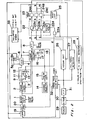
- a detail of the subcarrier generation circuit disclosed in this publication 58-152070 will be described below in connection with Fig. 1.
- a reference number 1 designates a burst gate circuit which, in accordance with the burst gate pulse in the horizontal scanning period, separates and generates a burst gate signal from the chrominance signal.
- a reference number 2 is a phase detector for the automatic phase controller (APC)
- 3 is a low pass filter
- 4 is a voltage-controlled oscillator (VCO).
- VCO 4 is provided with two crystal vibrators 5a and 5b for generating a signal at a frequency 3.58 MHz or 4.43 MHz.
- a switching circuit 6 is provided for selectively connecting one crystal vibrator to VCO 4 in response to the frequency of the burst signal.
- phase detector 7 for a killer.
- flip-flop 8 When phase detector 7 stops producing the normal signal, flip-flop 8 reverses its condition upon receipt of a driving pulse having a pulse width of about 200 milliseconds.
- the output of flip-flop 8 is connected to switching circuit 6 for selecting one vibrator.
- the operation of the subcarrier generation circuit of Fig. 1 is as follows.
- a burst signal having a frequency 3.58 MHz is separated and produced from burst gate circuit 1.
- the burst signal is applied to both phase detectors 2 and 7.
- switching circuit 6 is so actuated as to connect crystal vibrator 5a with VCO 4 in accordance with the output signal from flip-flop 8, and at the same time, the APC loop operates in a synchronized relationship with the burst signal at a frequency 3.58 MHz.
- VCO 4 produces a subcarrier wave having a frequency 3.58 MHz.
- phase detector 7 produces a phase detected signal which suspends the further operation of flip-flop 8.
- VCO 4 produces the normal 3.58 MHz subcarrier wave in a stable condition.
- switching circuit 6 may be so operated as to connect crystal vibrator 5b (4.43 MHz) to VCO 4.
- the signal in the APC loop loses the synchronization, thereby no output signal is produced from phase detector 7.
- flip-flop 8 changes its condition upon receipt of a next drive pulse, thereby switching the switching circuit 6 to connect crystal vibrator 5a (3.58 MHz) to VCO 4.
- APC loop is synchronized at a frequency 3.58 MHz, so that VCO 4 produces a normal subcarrier wave at frequency 3.58 MHz.
- the first disadvantage is about an error operation which may take place when a television signal of the SECAM system is received.
- chrominance signal contains a subcarrier wave at a frequency 4.25 MHz or 4.406 MHz, which is very close to the frequency 4.43 MHz of the burst signal. Accordingly, if the signal component at the trailing edge of the horizontal sync signal where the burst signal of PAL system or NTSC system is located should come in while the television signal of the SECAM system is receiving, the APC circuit makes an retraction operation, resulting in an error operation as if the burst signal at 4.43 MHz is received.
- the second disadvantage is about an error operation which may take place upon change of the channel from a channel in one broadcasting system, such as a PAL system, to a channel in another broadcasting system, such as a SECAM system.
- the low pass filter defining the APC loop has a relatively long time constant. Therefore, when the channel change between two different broadcasting system is effected, it takes a relatively long time to detect the broadcasting system of the newly selected channel and to switch the switching circuit 6 so as to generate a proper subcarrier wave from VCO 4. During this period of time, the image on the screen is often distorted.
- the last disadvantage is about an error operation caused by a noise signal produced from flip-flop circuit 8 or a system detection circuit for detecting the type of broadcasting system now receiving.
- the system detection circuit detects and produces a signal representing the type of broadcasting system now receiving.
- the system detection circuit makes an error detection by the noise signal.
- the noise signal is, for example, contained in the received broadcasting signal, or produced upon reproduction of a tape recorded under a poor condition, or produced when the video search signal is added.
- the present invention has been developed with a view to substantially solving the above described disadvantages and has for its essential object to provide an improved multi-system television receiver which will not make any error operation by the noise signal caused by the change of the channel between two different broadcasting systems or by any other reasons described above.
- a multi-system television receiver is applicable to receive television signals of different systems, such as PAL system, NTSC system and SECAM system with a plurality of different subcarrier wave frequencies, and which comprises a frequency detecting circuit for detecting the frequency of a subcarrier wave of the television signal and producing frequency data representing the detected frequency, a system detecting circuit for detecting the system of the television signal and producing system data representing the detected system, channel change detecting circuit for detecting the channel change, holding circuit for holding the frequency data and the system data upon change of the channel detected by the detecting circuit, and television circuits which are set in a condition in compliance with the frequency data and the system data.
- PAL system NTSC system and SECAM system with a plurality of different subcarrier wave frequencies
- a frequency detecting circuit for detecting the frequency of a subcarrier wave of the television signal and producing frequency data representing the detected frequency
- a system detecting circuit for detecting the system of the television signal and producing system data representing the detected system
- channel change detecting circuit for detecting the channel change
- a multi-system television receiver comprises an APC loop including a voltage-controlled oscillator and vibrating elements coupled to the oscillator for the oscillation at different frequencies, a phase detector for detecting a phase difference between a burst signal of the television signal and oscillating signal from the oscillator, a flip-flop which is controlled by a signal produced from the phase detector, a circuit for generating a color killer signal for the SECAM system, and a switching circuit controlled by the flip-flop and the circuit for selecting one vibrating element for effecting the oscillation at a required frequency.
- a pulse generating circuit which generates a channel change pulse upon change of the channel
- the APC loop further comprises a low pass filter connected to the voltage controlled oscillator.
- the low pass filter has a time constant setting circuit for making the time constant of the low pass filter short when the channel change pulse is present.
- the phase detector also has a time constant setting circuit for making the time constant of the phase detector short when the channel change pulse is present.
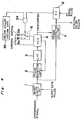
- a tuner 29 for receiving television signals and producing a tuned television signal is connected to a sound-trap 30 and further to a picture intermediate frequency (PIF) 31.
- PIF 31 is connected to each of a SECAM circuit 26, a PAL/NTSC detector 27 and a video trap 32.
- Video trap 32 which is also coupled to a video circuit (not shown), is connected to a band pass filter (BPF) 19 and further to a band pass amplifier 20. Accordingly, band pass amplifier 19 produces a chrominance signal which is applied to a burst gate circuit 1.
- Burst gate circuit 1 operates in response to the burst gate pulse.
- the output of burst gate circuit 1 is connected to a phase detector 2 for use in an automatic phase controller (APC).
- APC automatic phase controller
- a low pass filter 3 is connected to phase detector 2 and further to a voltage-controlled oscillator 4 which is coupled with a switching circuit 6 having crystal vibrators 5a and 5b for the oscillation at different frequencies 3.58 MHz and 4.43 MHz, respectively.
- An automatic phase controller is defined by a feed back loop containing phase detector 2, low pass filter 3 and VCO 4. Accordingly, VCO 4 produces a subcarrier signal at a frequency 3.58 MHz or 4.43 MHz depending on the frequency of the burst signal, in a manner which will be described in detail later.
- low pass filter 3 comprises a capacitor 9 connected between a hot line, through which the signal transmits, and ground. Also, a series connection of a resistor 11 and a capacitor 10 is connected parallel to capacitor 9. Furthermore, a series connection of a capacitor 12 and a normally-closed switch 13 is connected parallel to capacitor 10. On and off of normally-closed switch 13 is controlled by a pulse from a pulse generator 15 in a manner which will be described later.
- VCO 4 The output of VCO 4 is applied to a PAL/NTSC demodulator 33 which produces R-Y signal or B-Y signal.
- the output of VCO 4 is also applied to a phase detector 7, which also receives the output signal from burst gate circuit 1.
- phase detector 7 is connected with a capacitor 16 which is grounded. Also, a series connection of capacitor 17 and a normally-closed switch 18 is connected parallel to capacitor 16. On and off of normally-closed switch 18 is also controlled by a pulse from pulse generator 15 in a manner described below.
- a channel selector 14 is coupled to a pulse generator 15. Whenever the broadcasting channel is changed by channel selector 14, pulse generator 15 generates a short pulse, such as shown by waveform d in Fig. 3. The short pulse is applied to each of normally-closed switches 13 and 18 so as to turn them off temporarily, such as, during the pulse duration.
- switch 13 turns off, capacitor 12 is disconnected from capacitor 10, thereby making the time constant of low pass filter 3 short.
- switch 18 turns off, time constant of phase detector 7 is shortened.
- time constant is shortened, the retraction operation of the APC loop becomes faster, whereby the subcarrier wave for the newly selected channel may be produced very fast from VCO. This quick response can be accomplished even when the channel change is effected between two different broadcasting systems having different subcarrier wave frequencies. Accordingly, a stable subcarrier wave can be obtained immediately after the change of the channel.
- Phase detector 7 is provided to produce a color killer output, which is applied to both band pass amplifier 20 and flip-flop circuit 8.
- flip-flop 8 When.VCO 4 is producing a subcarrier signal having a frequency 3.58 MHz, flip-flop 8 generates HIGH in response to the signal obtained from phase detector 7. Similarly, when VCO 4 is producing a subcarrier signal having a frequency 4.43 MHz, flip-flop 8 generates LOW.
- the output of flip-flop 8, such as shown in Fig. 3 at waveform a, is applied to AND gate 22a provided in a detection control circuit 22.
- Detection control circuit 22 further includes AND gates 22b and 22c and a pulse generator 22d.
- One input of AND gate 22b is connected to SECAM circuit 26 which produces HIGH when the received television signal is the SECAM system, and LOW when it is not, such as indicated in Fig. 3, waveform b.
- One input of AND gate 22c is connected to PAL/NTSC detector 27 which produces HIGH when the received television signal is NTSC system and LOW when it is either PAL system or SECAM system, such as indicated in Fig. 3, waveform c.
- the other inputs of AND gates 22a, 22b and 22c are connected to pulse generator 22d.
- Pulse generator 22d has its input connected to an OR gate 22e having two inputs.
- One input of OR gate 22e is connected to pulse generator 15 and the other input thereof is connected to a television signal detector 28. The detail of pulse generator 22d will be described later.
- Television signal detector 28 has two inputs: one for receiving horizontal pulse; and the other for receiving sync-pulse. Accordingly, whenever a television signal, which may be obtained through the antenna (not shown), cable (not shown), or from a video tape, is being received, television signal detector 28 generates a HIGH, such as shown in Fig. 3 at waveform e. Thus, television signal detector 28 produces LOW while the channel is being changed.
- the signal produced from television signal detector 28 is similar to the signal produced from pulse generator 15, except that the these two signals are in the opposite phase.
- the signal from television signal detector 28 has such a feature that, when a video tape is being reproduced, the channel change recorded in the tape can also be detected. Therefore, whenever there is a channel change in the reproduced video tape, no pulse will be produced from pulse generator 15, but a pulse will be produced from television signal detector 28.
- OR gate 22e produces a signal not only when the channel is actually changed, but also when the channel change recorded in the video tape is detected.
- pulse generator 22d detects a step up of a waveform d or a step up of a waveform e, and produces a one-shot pulse having a pulse duration of t or t'. Accordingly, AND gates 22a, 22b and 22c are enabled only when one-shot pulse is present, that is a short period of time immediately after the channel change is effected which may be an actual channel change or a channel change recorded in the video tape.
- AND gates 22a, 22b and 22c are connected to a hold circuit 23 which is coupled to a reset circuit 25.
- Reset circuit 25 receives the signal from television signal detector 28 and produces a reset signal when the channel is changed. Accordingly, when a new channel is selected, the output signal from AND gate 22a is held in hold circuit 23, and is produced from output terminal 24A of hold circuit 23. Similarly, the output signal from AND gate 22b is held and produced from output terminal 24B, and output signal from AND gate 22c is held and produced from output terminal 24C.
- Output terminal 24A carrying data of subcarrier frequency, is connected to switching circuit 6 for selecting either one of crystal vibrators 5a and 5b, and also to band pass filter 19, video trap 32 and sound trap 30.
- Output terminal 24B carrying data representing the SECAM system, is connected to SECAM circuit 26 for maintaining the SECAM circuit operative while the received television signal is SECAM system.
- Output terminal 24C carrying data representing the PAL system or NTSC system, is connected to PAL/NTSC demodulator 33 for actuating demodulator 33.
- output terminal 24C When the received television signal is PAL system, output terminal 24C will produce LOW, thereby setting demodulator 33 as a PAL demodulator.
- output terminal 24C When the received television signal is NTSC system, output terminal 24C will produce HIGH, thereby setting demodulator 33 as a NTSC demodulator.
- the television receiver according to the embodiment shown in Fig. 2 is operable to five different broadcasting systems, which are: PAL system with 3.58 MHz subcarrier wave; PAL system with 4.43 MHz subcarrier wave; NTSC system with 3.58 MHz subcarrier wave; NTSC system with 4.43 MHz subcarrier wave; and SECAM system with 4.43 MHz.
- channel selector 14 is now being actuated to select a television signal of NTSC system with 3.58 MHz subcarrier wave.
- pulse generator 15 produces a pulse (first pulse in waveform d) which affects pulse generator 22d to produce a one-shot pulse (first pulse in waveform f). While the one-shot pulse is present, flip-flop 8 produces HIGH indicating that the subcarrier wave has a frequency 3.58 MHz.
- SEC AM circuit 26 produces LOW indicating that the received television signal is not the SECAM system
- P AL/ NTSC detector 27 produces HIGH indicating that the received television signal is NTSC system.
- each of AND gates 22a and 22c produces HIGH (waveforms g and i), and AND gate 22b produces no pulse (waveform h).
- the signals from AND gates 22a, 22b and 22c are produced in response to the one-shot pulse, and are held in holding circuit 23 which accordingly produces HIGH, LOW and HIGH, respectively, from its output terminals 24A, 24B and 24C. These signals produced from output terminals 24A, 24B, and 24C are maintained until reset circuit produces a reset signal, that is until the next channel change.
- the HIGH from output terminal 24A is applied to switching circuit 6 for selecting crystal vibrator 5a for the oscillation at the frequency 3.58 MHz.
- the HIGH from output terminal 24A is also applied to band pass filter 19 for selecting a band appropriate for the 3.58 MHz subcarrier wave, and further to video trap 32 and to sound trap 30.
- the LOW from output terminal 24B is applied to SECAM circuit 26 so as to disable the SECAM circuit 26.
- the HIGH from output terminal 24C is applied to PAL/NTSC demodulator 33 so as to set demodulator 33 as a NTSC demodulator.
- the television receiver not only automatically sets the circuit in a condition suitable for the system of the received television signal, but also maintains the set condition as long as the channel is maintained the same.
- the channel change is effected by channel selector 14, or when the channel change signal as recorded in the video tape is reproduced, new data will be set and held in hold circuit 23.
- detection control circuit 22 employs AND gates 22a, 22b and 22c, but these AND gates can be replaced with other logic gates, such as NOR gates, in the case where the pulses applied to the gates are in the negative form.
- a modification of a subcarrier generation circuit is shown.
- the output of flip-flop 8 is connected to an OR gate 34 which also receives a signal from a SECAM killer 35 in a SECAM circuit.
- the output of OR gate 34 is connected to switching circuit 6. The operation of this circuit is described below.
- flip-flop 8 When the television signal of NTSC system is receiving, flip-flop 8 produces HIGH in a manner described above. Then, the HIGH is applied through OR gate 34 to switching circuit 6 so as to oscillate at 3.58 MHz by crystal vibrator 5a. Accordingly, the APC loop synchronizes at the frequency 3.58 MHz and therefore, the VCO generates subcarrier wave at 3.58 MHz.
- flip-flop 8 When the television signal of PAL system is receiving, flip-flop 8 produces LOW in a manner described above. Then, the LOW is applied through OR gate 34 to switching circuit 6 so as to oscillate at 4.43 MHz by crystal vibrator 5b. Accordingly, the APC loop synchronizes at the frequency 4.43 MHz and therefore, the VCO generates subcarrier wave at 4.43 MHz.
- SECAM KILLER 35 for the SECAM color killer When the television signal of SECAM system is receiving, SECAM KILLER 35 for the SECAM color killer produces HIGH. Therefore, regardless of the signal from flip-flop 8, OR gate 34 produces HIGH. Accordingly, switching circuit 6 is so turned as to oscillate at 3.5b MHz. In this case, subcarrier wave component at the frequency 4.25 MHz or 4.406 MHz contained in the chrominance signal may be applied to phase detector 2. Since such frequencies are much different from 3.58 MHz, VCO 4 generates subcarrier wave at 3.58 MHz without making any retraction operation by the APC loop.
- the color killer output produced from phase detector 7 may be use for disabling a color processing circuit for the NTSC/PAL system and for enabling a color processing circuit for the SECAM system.
- a circuit diagram of a low pass filter is shown.
- low pass filter 3 shown in Fig. 2 a series connection of capacitor 12 and normally- close switch 13 is connected parallel to capacitor 10 so as to shorten the time constant when switch 13 opens.
- a series connection of a resistor 36 and a normally-open switch 13' is connected parallel to capacitor 10. Accordingly, when the channel change is effected, switch 13' closes to shorten the time constant. Accordingly, low pass filter 3 shown in Fig. 2 can be replaced with low pass filter 3 shown in Fig. 5.
Landscapes
- Engineering & Computer Science (AREA)
- Multimedia (AREA)
- Signal Processing (AREA)
- Color Television Systems (AREA)
- Processing Of Color Television Signals (AREA)
Applications Claiming Priority (6)
| Application Number | Priority Date | Filing Date | Title |
|---|---|---|---|
| JP1984075991U JPS60189187U (ja) | 1984-05-23 | 1984-05-23 | 副搬送波自動切換回路 |
| JP75991/84 | 1984-05-23 | ||
| JP8127584U JPS60192578U (ja) | 1984-05-30 | 1984-05-30 | 副搬送波自動切換回路 |
| JP81275/84 | 1984-05-30 | ||
| JP17199384U JPS6188378U (de) | 1984-11-13 | 1984-11-13 | |
| JP171993/84 | 1984-11-13 |
Publications (3)
| Publication Number | Publication Date |
|---|---|
| EP0162443A2 true EP0162443A2 (de) | 1985-11-27 |
| EP0162443A3 EP0162443A3 (en) | 1987-12-16 |
| EP0162443B1 EP0162443B1 (de) | 1991-12-11 |
Family
ID=27302012
Family Applications (1)
| Application Number | Title | Priority Date | Filing Date |
|---|---|---|---|
| EP85106206A Expired EP0162443B1 (de) | 1984-05-23 | 1985-05-21 | Mehrsystemfernsehempfänger |
Country Status (9)
| Country | Link |
|---|---|
| US (1) | US4688082A (de) |
| EP (1) | EP0162443B1 (de) |
| AU (1) | AU568208B2 (de) |
| BR (1) | BR8502420A (de) |
| CA (1) | CA1252880A (de) |
| DE (1) | DE3584851D1 (de) |
| EG (1) | EG17278A (de) |
| ES (1) | ES8702761A1 (de) |
| PH (1) | PH23137A (de) |
Cited By (10)
| Publication number | Priority date | Publication date | Assignee | Title |
|---|---|---|---|---|
| EP0196509A3 (de) * | 1985-03-23 | 1988-12-21 | Blaupunkt-Werke GmbH | Schaltungsanordnung zum Betrieb eines Fernsehwiedergabegerätes in zwei Betriebsarten |
| DE4024228A1 (de) * | 1989-07-31 | 1991-02-14 | Gold Star Co | Schaltung zum automatischen umschalten der drei betriebsarten eines farbfernsehgeraetes |
| FR2658023A1 (fr) * | 1990-02-06 | 1991-08-09 | Sgs Thomson Microelectronics | Procede d'identification automatique d'un standard de television couleur. |
| EP0393352A3 (de) * | 1989-04-20 | 1991-10-23 | Motorola, Inc. | OSD-Mehrnormfernsehempfänger |
| EP0462746A3 (en) * | 1990-06-21 | 1992-10-28 | Gold Star Co. Ltd | Automatic reproducing system of a vcr |
| EP0548891A1 (de) * | 1991-12-20 | 1993-06-30 | Eastman Kodak Company | Mehrmoden-Videonormauswahlschaltung und Auswahlverfahren |
| EP0591707A3 (en) * | 1992-10-05 | 1994-06-22 | Loewe Opta Gmbh | Method for converting digitalized television signals |
| EP0777382A3 (de) * | 1995-11-28 | 1999-01-20 | Matsushita Electric Industrial Co., Ltd. | Verfahren und Vorrichtung zum Auswählen eines Rundfunkkanals |
| EP0762754A3 (de) * | 1995-08-25 | 1999-01-27 | Sony Corporation | Automatischer Modusdetektor für Fernsehübertragungssystem |
| DE19801527C2 (de) * | 1997-01-17 | 2003-10-02 | Samsung Electronics Co Ltd | Vielsystem-Empfangsdemodulator |
Families Citing this family (26)
| Publication number | Priority date | Publication date | Assignee | Title |
|---|---|---|---|---|
| JPH02109486A (ja) * | 1988-10-19 | 1990-04-23 | Matsushita Electric Ind Co Ltd | 自動周波数切替装置 |
| DE68928197T2 (de) * | 1988-12-23 | 1997-12-11 | Matsushita Electric Ind Co Ltd | Videobandrekorder mit Fernsehnormwandler |
| US5119177A (en) * | 1989-07-31 | 1992-06-02 | Goldstar Co., Ltd. | Automatic 3-mode switching circuit of a color television set |
| JP2973491B2 (ja) * | 1990-08-22 | 1999-11-08 | ソニー株式会社 | Ntsc/pal信号判別回路およびこの判別回路を用いたアクティブフィルタ |
| JPH04299610A (ja) * | 1991-03-27 | 1992-10-22 | Rohm Co Ltd | フィルタ装置 |
| US5311296A (en) * | 1991-11-12 | 1994-05-10 | Rohm Co., Ltd. | Video signal generator circuit and video image processing device using the same |
| MY111174A (en) * | 1991-12-13 | 1999-09-30 | Thomson Consumer Electronics Inc | On/off control of a cable converter unit by a vcr |
| MY108249A (en) * | 1991-12-13 | 1996-08-30 | Thomson Consumer Electronics Inc | A detector circuit for use in a vcr |
| KR0170246B1 (ko) * | 1992-02-28 | 1999-03-20 | 강진구 | 방송방식 자동선택 장치 |
| US5444491A (en) * | 1993-02-26 | 1995-08-22 | Massachusetts Institute Of Technology | Television system with multiple transmission formats |
| JPH0818994A (ja) * | 1994-06-30 | 1996-01-19 | Sony Corp | マルチ映像信号復調装置 |
| US5796442A (en) * | 1994-11-02 | 1998-08-18 | Texas Instruments Incorporated | Multi-format television reciever |
| JP2972542B2 (ja) * | 1995-03-15 | 1999-11-08 | 日本電気株式会社 | 色信号処理回路 |
| US5896179A (en) * | 1995-03-31 | 1999-04-20 | Cirrus Logic, Inc. | System for displaying computer generated images on a television set |
| US5771073A (en) * | 1995-06-07 | 1998-06-23 | Massachusetts Institute Of Technology | Advanced television system using a different encoding technique for non-image areas |
| JP3500883B2 (ja) * | 1996-12-12 | 2004-02-23 | 松下電器産業株式会社 | カラー方式判別回路 |
| US6366327B1 (en) * | 1997-12-22 | 2002-04-02 | Texas Instruments Incorporated | Vertical sync detection and output for video decoder |
| WO2000001162A1 (en) * | 1998-06-29 | 2000-01-06 | Matsushita Electric Industrial Co., Ltd. | Color transmission system discrimination circuit in television set |
| KR20000026823A (ko) * | 1998-10-23 | 2000-05-15 | 구자홍 | 방송방식 자동판별장치 및 방법 |
| JP2001359115A (ja) * | 2000-06-09 | 2001-12-26 | Nec Corp | テレビ信号カラ−システム判別装置 |
| JP3978397B2 (ja) * | 2000-09-26 | 2007-09-19 | 松下電器産業株式会社 | 受信装置及び受信装置の制御方法 |
| US6670997B1 (en) | 2000-11-15 | 2003-12-30 | Thomson Licensing S.A. | Autodetermination of appropriate television signal standard in a television signal receiver |
| JP2002165150A (ja) * | 2000-11-28 | 2002-06-07 | Mitsubishi Electric Corp | 受信装置 |
| KR101017371B1 (ko) * | 2004-03-22 | 2011-02-28 | 삼성전자주식회사 | 방송 방식 자동 판별 장치 및 방법 |
| CN1969544A (zh) * | 2004-06-14 | 2007-05-23 | 汤姆逊许可公司 | 视频信号处理器中转换电视频道的系统和方法 |
| KR20160037656A (ko) * | 2014-09-29 | 2016-04-06 | 삼성전자주식회사 | 에러 검출기 및 발진기의 에러 검출 방법 |
Family Cites Families (10)
| Publication number | Priority date | Publication date | Assignee | Title |
|---|---|---|---|---|
| DE1229139B (de) * | 1964-06-25 | 1966-11-24 | Saba Gmbh | Schaltungsanordnung zur Umschaltung des Fangbereiches der Phasensynchronisation des Referenzoszillators in Farbfernseh-Empfaengern |
| US3795762A (en) * | 1969-06-11 | 1974-03-05 | Rca Corp | Plural operating mode television receivers |
| JPS5136093B1 (de) * | 1971-02-13 | 1976-10-06 | ||
| EP0013596B1 (de) * | 1979-01-09 | 1983-11-23 | Rca Corporation | Vorrichtung zur Verzögerungsregelung des Leuchtdichtesignals in einem PAL/SECAM-Fernsehempfänger |
| US4253116A (en) * | 1979-11-27 | 1981-02-24 | Rca Corporation | Television synchronizing system operable from nonstandard signals |
| DE3137447C2 (de) * | 1980-11-19 | 1987-02-19 | Philips Patentverwaltung Gmbh, 2000 Hamburg | Farbfernsehempfänger-Schaltungsanordnung zur Identifikation der Norm |
| JPS57192190A (en) * | 1981-05-21 | 1982-11-26 | Sony Corp | Processing circuit for chrominance signal |
| JPS58151187A (ja) * | 1982-03-03 | 1983-09-08 | Mitsubishi Electric Corp | 多方式カラ−テレビジヨン受像機の方式切換装置 |
| GB2148652B (en) * | 1983-09-15 | 1987-09-09 | Sinclair Res Ltd | Television receivers |
| US4727362A (en) * | 1984-07-16 | 1988-02-23 | International Business Machines Corporation | Digital display system |
-
1985
- 1985-05-16 US US06/735,048 patent/US4688082A/en not_active Expired - Lifetime
- 1985-05-17 AU AU42601/85A patent/AU568208B2/en not_active Expired
- 1985-05-21 EP EP85106206A patent/EP0162443B1/de not_active Expired
- 1985-05-21 DE DE8585106206T patent/DE3584851D1/de not_active Expired - Lifetime
- 1985-05-22 CA CA000482033A patent/CA1252880A/en not_active Expired
- 1985-05-22 BR BR8502420A patent/BR8502420A/pt not_active IP Right Cessation
- 1985-05-22 PH PH32301A patent/PH23137A/en unknown
- 1985-05-23 EG EG314/85A patent/EG17278A/xx active
- 1985-05-23 ES ES85543442A patent/ES8702761A1/es not_active Expired
Cited By (12)
| Publication number | Priority date | Publication date | Assignee | Title |
|---|---|---|---|---|
| EP0196509A3 (de) * | 1985-03-23 | 1988-12-21 | Blaupunkt-Werke GmbH | Schaltungsanordnung zum Betrieb eines Fernsehwiedergabegerätes in zwei Betriebsarten |
| EP0393352A3 (de) * | 1989-04-20 | 1991-10-23 | Motorola, Inc. | OSD-Mehrnormfernsehempfänger |
| DE4024228A1 (de) * | 1989-07-31 | 1991-02-14 | Gold Star Co | Schaltung zum automatischen umschalten der drei betriebsarten eines farbfernsehgeraetes |
| FR2658023A1 (fr) * | 1990-02-06 | 1991-08-09 | Sgs Thomson Microelectronics | Procede d'identification automatique d'un standard de television couleur. |
| EP0441723A1 (de) * | 1990-02-06 | 1991-08-14 | Sgs Thomson Microelectronics Sa | Automatisches Verfahren zur Farbfernsehnormidentifizierung |
| US5192997A (en) * | 1990-02-06 | 1993-03-09 | Sgs-Thomson Microelectronics S.A. | Automatic method for identifying a color tv standard |
| EP0462746A3 (en) * | 1990-06-21 | 1992-10-28 | Gold Star Co. Ltd | Automatic reproducing system of a vcr |
| EP0548891A1 (de) * | 1991-12-20 | 1993-06-30 | Eastman Kodak Company | Mehrmoden-Videonormauswahlschaltung und Auswahlverfahren |
| EP0591707A3 (en) * | 1992-10-05 | 1994-06-22 | Loewe Opta Gmbh | Method for converting digitalized television signals |
| EP0762754A3 (de) * | 1995-08-25 | 1999-01-27 | Sony Corporation | Automatischer Modusdetektor für Fernsehübertragungssystem |
| EP0777382A3 (de) * | 1995-11-28 | 1999-01-20 | Matsushita Electric Industrial Co., Ltd. | Verfahren und Vorrichtung zum Auswählen eines Rundfunkkanals |
| DE19801527C2 (de) * | 1997-01-17 | 2003-10-02 | Samsung Electronics Co Ltd | Vielsystem-Empfangsdemodulator |
Also Published As
| Publication number | Publication date |
|---|---|
| EG17278A (en) | 1991-03-30 |
| PH23137A (en) | 1989-05-11 |
| DE3584851D1 (de) | 1992-01-23 |
| US4688082A (en) | 1987-08-18 |
| ES8702761A1 (es) | 1986-12-16 |
| ES543442A0 (es) | 1986-12-16 |
| EP0162443B1 (de) | 1991-12-11 |
| CA1252880A (en) | 1989-04-18 |
| BR8502420A (pt) | 1986-01-21 |
| AU568208B2 (en) | 1987-12-17 |
| EP0162443A3 (en) | 1987-12-16 |
| AU4260185A (en) | 1985-11-28 |
Similar Documents
| Publication | Publication Date | Title |
|---|---|---|
| US4688082A (en) | Multi-system television receiver | |
| JPH0566076B2 (de) | ||
| JPS649791B2 (de) | ||
| US4942472A (en) | Detection circuit for a video tape recorder signal | |
| CA1050157A (en) | Color video reproducing apparatus | |
| CA1143830A (en) | Television horizontal afpc with phase detector driven at twice the horizontal frequency | |
| EP0067201B1 (de) | Horizontal-phasenverriegelungsschleife für fernsehgeräte | |
| US4731675A (en) | Dropout correcting apparatus wherein dropout detecting flog signal is superimposed on reproduced video signal | |
| US4992872A (en) | Method of synchronizing the horizontal deflection of electron beams in television receivers | |
| CA1262281A (en) | Multi-system television receiver | |
| US5404230A (en) | Color burst phase correcting color signal reproducing circuit | |
| KR900000126B1 (ko) | 다중시스템 텔레비젼 수신기 | |
| US4490750A (en) | Apparatus for reproducing a video signal | |
| EP0145293A1 (de) | Magnetisches Aufzeichnungs-/Wiedergabegerät | |
| JPH0336148Y2 (de) | ||
| JPS6150557B2 (de) | ||
| CN1009607B (zh) | 多制式电视接收机 | |
| JPH0217993B2 (de) | ||
| EP0066848A2 (de) | Aufzeichnungsgerät für ein Fernsehsignal | |
| JPH04188960A (ja) | 垂直同期信号切換装置 | |
| JP3599253B2 (ja) | Pal/secam信号判別回路およびテレビジョン信号受信装置 | |
| KR100271591B1 (ko) | 크로마 신호 기록 처리 회로 | |
| JPH06165216A (ja) | 色信号記録回路 | |
| JPH01132285A (ja) | 画像メモリ制御装置 | |
| JPH01132284A (ja) | 画像メモリ制御装置 |
Legal Events
| Date | Code | Title | Description |
|---|---|---|---|
| PUAI | Public reference made under article 153(3) epc to a published international application that has entered the european phase |
Free format text: ORIGINAL CODE: 0009012 |
|
| AK | Designated contracting states |
Kind code of ref document: A2 Designated state(s): DE FR GB |
|
| 17P | Request for examination filed |
Effective date: 19861231 |
|
| PUAL | Search report despatched |
Free format text: ORIGINAL CODE: 0009013 |
|
| AK | Designated contracting states |
Kind code of ref document: A3 Designated state(s): DE FR GB |
|
| 17Q | First examination report despatched |
Effective date: 19900319 |
|
| GRAA | (expected) grant |
Free format text: ORIGINAL CODE: 0009210 |
|
| AK | Designated contracting states |
Kind code of ref document: B1 Designated state(s): DE FR GB |
|
| REF | Corresponds to: |
Ref document number: 3584851 Country of ref document: DE Date of ref document: 19920123 |
|
| ET | Fr: translation filed | ||
| PLBE | No opposition filed within time limit |
Free format text: ORIGINAL CODE: 0009261 |
|
| STAA | Information on the status of an ep patent application or granted ep patent |
Free format text: STATUS: NO OPPOSITION FILED WITHIN TIME LIMIT |
|
| 26N | No opposition filed | ||
| REG | Reference to a national code |
Ref country code: GB Ref legal event code: IF02 |
|
| PGFP | Annual fee paid to national office [announced via postgrant information from national office to epo] |
Ref country code: FR Payment date: 20040510 Year of fee payment: 20 |
|
| PGFP | Annual fee paid to national office [announced via postgrant information from national office to epo] |
Ref country code: GB Payment date: 20040519 Year of fee payment: 20 |
|
| PGFP | Annual fee paid to national office [announced via postgrant information from national office to epo] |
Ref country code: DE Payment date: 20040603 Year of fee payment: 20 |
|
| PG25 | Lapsed in a contracting state [announced via postgrant information from national office to epo] |
Ref country code: GB Free format text: LAPSE BECAUSE OF EXPIRATION OF PROTECTION Effective date: 20050520 |
|
| REG | Reference to a national code |
Ref country code: GB Ref legal event code: PE20 |