EP0162597A2 - Fiche électrique domestique à assemblage aisé - Google Patents
Fiche électrique domestique à assemblage aisé Download PDFInfo
- Publication number
- EP0162597A2 EP0162597A2 EP85302871A EP85302871A EP0162597A2 EP 0162597 A2 EP0162597 A2 EP 0162597A2 EP 85302871 A EP85302871 A EP 85302871A EP 85302871 A EP85302871 A EP 85302871A EP 0162597 A2 EP0162597 A2 EP 0162597A2
- Authority
- EP
- European Patent Office
- Prior art keywords
- plug
- insert
- recess
- insert portion
- electrical
- Prior art date
- Legal status (The legal status is an assumption and is not a legal conclusion. Google has not performed a legal analysis and makes no representation as to the accuracy of the status listed.)
- Withdrawn
Links
Images


Classifications
-
- H—ELECTRICITY
- H01—ELECTRIC ELEMENTS
- H01R—ELECTRICALLY-CONDUCTIVE CONNECTIONS; STRUCTURAL ASSOCIATIONS OF A PLURALITY OF MUTUALLY-INSULATED ELECTRICAL CONNECTING ELEMENTS; COUPLING DEVICES; CURRENT COLLECTORS
- H01R13/00—Details of coupling devices of the kinds covered by groups H01R12/70 or H01R24/00 - H01R33/00
- H01R13/46—Bases; Cases
- H01R13/502—Bases; Cases composed of different pieces
- H01R13/512—Bases; Cases composed of different pieces assembled by screw or screws
-
- H—ELECTRICITY
- H01—ELECTRIC ELEMENTS
- H01R—ELECTRICALLY-CONDUCTIVE CONNECTIONS; STRUCTURAL ASSOCIATIONS OF A PLURALITY OF MUTUALLY-INSULATED ELECTRICAL CONNECTING ELEMENTS; COUPLING DEVICES; CURRENT COLLECTORS
- H01R13/00—Details of coupling devices of the kinds covered by groups H01R12/70 or H01R24/00 - H01R33/00
- H01R13/58—Means for relieving strain on wire connection, e.g. cord grip, for avoiding loosening of connections between wires and terminals within a coupling device terminating a cable
- H01R13/59—Threaded ferrule or bolt operating in a direction parallel to the cable or wire
-
- H—ELECTRICITY
- H01—ELECTRIC ELEMENTS
- H01R—ELECTRICALLY-CONDUCTIVE CONNECTIONS; STRUCTURAL ASSOCIATIONS OF A PLURALITY OF MUTUALLY-INSULATED ELECTRICAL CONNECTING ELEMENTS; COUPLING DEVICES; CURRENT COLLECTORS
- H01R13/00—Details of coupling devices of the kinds covered by groups H01R12/70 or H01R24/00 - H01R33/00
- H01R13/66—Structural association with built-in electrical component
- H01R13/68—Structural association with built-in electrical component with built-in fuse
-
- H—ELECTRICITY
- H01—ELECTRIC ELEMENTS
- H01R—ELECTRICALLY-CONDUCTIVE CONNECTIONS; STRUCTURAL ASSOCIATIONS OF A PLURALITY OF MUTUALLY-INSULATED ELECTRICAL CONNECTING ELEMENTS; COUPLING DEVICES; CURRENT COLLECTORS
- H01R4/00—Electrically-conductive connections between two or more conductive members in direct contact, i.e. touching one another; Means for effecting or maintaining such contact; Electrically-conductive connections having two or more spaced connecting locations for conductors and using contact members penetrating insulation
- H01R4/24—Connections using contact members penetrating or cutting insulation or cable strands
Definitions
- This invention concerns improvements relating to electrical plugs and particularly, though not exclusively, concerns electrical plugs of the type employed for coupling domestic and other electrical appliances to socket outlets of the mains electrical supply.
- an electrical plug in which we hold an interest and which comprises a body portion having terminal pins to be inserted into the corresponding openings of a socket outlet and an insert portion enterable into a recess in said body portion, the insert portion comprising a cable clamping arrangement and separate conductor-receiving channels for the separate conductors of the cable to which the plug is to be fitted, each of said channels being configured to receive a conductor end portion therein at a location to be accessed for making electrical contact thereto, and cooperating means being provided in said body portion and in said insert such that when the insert is entered into the recess in the body portion electrical continuity is established between the conductor end portions received in the channels of the insert and the terminal pins of the body portion; such an electrical plug will hereinafter be called a plug of the kind described.
- One of the two embodiments described in Wo 82/00387 aforementioned has pins or other electrical contact establishing means projecting into the recess in the body portion, and the insert is arranged to engage with the recess such that the pins enter into electrical contact with the conductor end portions engaged with the insert.
- the insert has contact-making terminal pins projecting therefrom which are adapted to mate with corresponding socket portions formed in an inner end wall of the recess and to enter such socket portions and contact the plug terminals when the insert is entered into the recess.
- the proposal furthermore in relation to the second embodiment was to spring load the contact-making terminal pins so that as the insert was forced manually into the recess in the plug body, so the contact-making terminal pins would be forced back against their spring bias by virtue of their engagement with the plug terminals and, by virtue of thus being forced back, would be forced into good contact with their respective conductors.
- insulation displacement techniques could advantageously be utilised so obviating the need to bare the conductor ends of their insulation.
- an electrical plug of the kind described further comprises means associated with the body portion of the plug for providing a mechanical advantage for facilitating the manual insertion of the insert into its accommodating recess in the plug body.
- the means for providing the required mechanical advantage comprises an internally screw-threaded component adapted for cooperation with an externally screw-threaded portion of the plug body to drive the insert positively into its accommodating recess when the screw threads are engaged with each other and the internally screw-threaded component is manually screwed down onto the plug body.
- the use of cooperating screw-threaded parts is considered to be preferable to other mechanical advantage providing arrangements, for example based on levers, on account not only of the widespread familiarity and consumer acceptance of screw-threaded parts, but also of the facility which an internally-screw threaded and thus hollow component provides for accommodating cable clamping parts of the insert within its hollow interior. This latter facility, as will be explained more fully hereinafter, enables an insert of the requisite size to be accommodated within the limited confines of a standard-sized plug body.
- the plug body has a generally cylindrical hollow protrusion from its rear surface (that is to say the surface where, in a conventional plug of similar terminal configuration and plug body shape, the cable would enter the plug body) and the external surface of such protrusion is screw-threaded.
- a pair of diametrically opposed slots extend the length of the protrusion through the cylindrical wall thereof for a purpose which will become clear.
- the recess in the plug body into which the insert is to be inserted aligns with the hollow interior of the protrusion, and the insert has a pair of ears which engage with the aforementioned slots when the insert is introduced into the protrusion, the ears projecting outwardly beyond the screw-threaded external surface of the protrusion.
- the arrangement is dimensioned such that the insert can readily be pushed manually into the protrusion and into the recess in the plug body to such an extent that the ears provided on the insert move along their receiving slots at least a distance sufficient to enable the internally screw-threaded component to be engaged with the protrusion and, as the two screw-threaded parts are screwed together, so the insert is positively driven into the plug body by engagement of the internally screw-threaded component with the ears of the insert.
- the plug of the kind described in WO 82/00387 aforementioned is particularly intended for use as a plug which is attachable onto a cable end by a user and, as desired, detachable subsequently from that cable and usable with another cable, namely as a rewirable plug
- the plug in question has attractions as a non-rewirable plug, that is a plug which is adapted to be attached to a cable and, once attached, is not intended to be removable therefrom.
- a plug of the kind described in which the insert, once inserted, was not removable from the plug body would constitute an advantageous form of non-rewirable plug not subject to problems which have plagued previous non-rewirable plug proposals and including the problem of loose conductor strands extending to the exterior of the plug body.
- the cooperation between the protrusion from the plug body and the component to be engaged therewith could advantageously be such that once the insert had been firmly engaged in the plug body recess, the component utilised to urge it home could not be removed.
- the protrusion from the plug body and the component to be engaged therewith could advantageously be such that once the insert had been firmly engaged in the plug body recess, the component utilised to urge it home could not be removed.
- latching teeth for securing the insert-driving component and the protrusion in their fully assembled condition, the assembly being effected with the aid of a press.
- the cooperating screw threads on the two parts could be retained but with the addition of formations arranged to irremovably interengage once the two parts had been fully screwed together.
- Yet another possibility would be simply to adhere or ultrasonically weld the insert-driving component onto the plug body protrusion once the insert has been fully driven home into the recess.
- the aforementioned ears which are provided on the insert can advantageously be provided at opposite ends of a part of the insert which has a number of apertures therethrough corresponding to the number of connections to be made by the plug, i.e. generally three insofar as the UK is concerned.
- the conductors of the cable to which the plug is to be fitted can advantageously be "woven" into these apertures in different directions, as will be explained more fully hereinafter, and by virtue of this arrangement any tension applied to the cable can at least to a substantial degree be prevented from manifesting itself in a force upon the connections made in the plug between the plug terminal pins and the cable conductors.
- a preferred form of cable clamping arrangement utilisable with either a rewirable or a non-rewirable plug in accordance with the present invention comprises a pair of spaced-apart limbs which are formed integrally with the insert and extend from the back end thereof, that is to say the end which is not introduced foremost into the insert-accommodating recess in the plug body portion, each of the limbs having at its free end a resilient finger which extends forwardly towards the front end of the insert within the space between the two limbs and is biassed by its resilience away from the respective limb; a cable to be clamped to the insert is passed between the free ends of the two fingers, which are capable of moving apart from one another a distance such as to accommodate different cable diameters, and the arrangement is such that any pull on the cable will cause the ends of the fingers to tend to grasp the cable and prevent it from being pulled out of their grasp.
- each of the said limbs there is advantageously also provided at the free end of each of the said limbs an outwardly facing portion having a number of screw thread sections engageable with the screw thread aforementioned which is provided on the interior surface of the hollow cylindrical component provided for driving home the insert.
- these screw thread sections provided on the limbs serve to provide a deterrent against any tendency for the insert to be pulled out of its accommodating recess in the plug body in the event of the cylindrical insert-driving component becoming partially unscrewed from the screw-threaded protrusion on the body part.
- a fuse carrier is pivotally mounted in a side wall of the plug body.
- a lever connected to the fuse carrier extends across the underside of the plug body so as to be inaccessible when the plug is plugged into a socket outlet.
- the lever enables the fuse carrier to be pivoted manually between a position where a fuse in the carrier engages fuse contacts within the plug body, and a position where a fuse in the carrier becomes accessible outside of the plug body and can be changed as may be necessary.
- the illustrated plug comprises a body portion 1 and an insert 2 enterable into a recess 3 in the body portion.
- the body portion 1 and the insert 2 are each formed of high impact, rigid synthetic plastics material and, as is schematically represented, brass terminal pins 4 are secured in the body portion 1 and brass strappings (not shown) couple the terminal pins 4 to conductor piercing pins 5 which project into the recess 3 from its inner end wall.
- a fuse holder 6 is provided in one side of the plug body 1 and will be described fully hereinafter.
- the boss 7 has a pair of slots 8 formed in its cylindrical wall for receiving a pair of ears 9 formed on the insert 2 when the insert is introduced into the hollow boss and thence into the recess 3, the ears 9 being of such a size as to project outwardly beyond the screw threads formed on the boss 7 when the insert 2 is inserted.
- An insert-driving component 10 in the form of an internally screw-threaded screw cap is arranged to thread onto the threads of the boss 7 and to bear upon the ears 9 of the insert 2 for driving the insert into the plug body 1 as the screw cap 10 is screwed down onto the plug body 1.
- An aperture (not shown) is provided in the end wall of the cap 10 for passage of a cable through the cap.
- the insert 2 has a portion 11 at its left-hand side (as viewed) which has first and second condcutor-receiving channels 12 and 13 in its upper surface (as viewed) and has a third conductor-receiving channel (not shown) intermediate the channels 12 and 13.
- Each of the three channels is formed with a shaped through aperture 14 which is designed to be capable of accepting and positively locating a variety of conductors of different sizes, and each of the apertures 14 communicates with a respective one of three conductor-piercing pin receiving bores 15 (see Fig. 4).
- Fig. 4 As shown by Fig.
- the apertures 14 have a rearwardly inclined profile which serves to assist in the retention of a conductor in the respective aperture, it being appreciated that in use of the insert 2 the conductors are laid into the channels 12,13 and the not shown under channel and their free ends are inserted into the apertures 14 and bent back upon themselves so as substantially to follow the inclined rear profile of the apertures; in this manner the conductors virtually "hook” onto the insert. With the three conductors of a cable thus assembled into the insert 2, insertion of the insert fully into its accommodating recess 3 in the plug body 1 causes the conductor-piercing pins 5 to enter the bores 15 and pierce through the conductor insulation thereby making electrical contact with the conductor strands.
- the generally-elongated, egg-shaped section of the apertures 14 not only enables different conductor sizes to be accommodated with positive centering of the conductors relative to the bores 15 regardless of the conductor size, but also enables the conductor strands to displace as the conductors are pierced by the pins 5 thereby minimising the possibility of conductor strands being severed by the pins 5.
- the portion 11 of the insert 2 has a pair of limbs 16 extending from its rear (that is towards the right hand side as viewed in Fig. 3), the limbs 16 carrying the aforementioned ears 9 and also carrying a cable clamping arrangement generally designated 17 (see Fig. 6).
- the cable clamping arrangement 17 comprises a pair of fingers 18 formed integrally with the insert and attached to the inner facing surfaces of the limbs 16 at the free ends thereof, the fingers 18 being resiliently biassed towards each other at their free ends so as to define a cable-clamping jaw between their opposed ends (see Fig. 6).
- the fingers 18 can move apart from each other to accommodate different sizes of cables.
- any pull on the cable in a direction such as to tend to pull it out of engagement with the insert 2 will cause the tips of the fingers 18 to grasp the cable more tightly.
- the insert 2 of Figs. 3 to 6 furthermore incorporates a means such as to resist any tendency for the insert to be pulled out of the plug body if the insert-driving component 10 is slightly loosened on the boss 7 and the cable is pulled.
- a means such as to resist any tendency for the insert to be pulled out of the plug body if the insert-driving component 10 is slightly loosened on the boss 7 and the cable is pulled.
- At the outer extremities of the limbs 16 there are provided section of screw threads 19 of the same size and pitch as those on the boss 7 and on the component 10. As the component 10 is screwed down fully onto the plug body 1, so these screw thread sections 19 align themselves with the screw threads of the boss 7 and of the component 10. If the component 10 is then slackened off a number of turns, this does not cause the insert 2 to be pulled back out of its accommodating recess in the plug body 1.
- Figs. 7, 8 and 9 there is shown therein an alternative form of insert usable with the plug body 1 and insert-driving component 10 of Figs. 1 and 2.
- the insert 2 of Figs. 7, 8 and 9 has a portion 11, ears 9 and limbs 16 with screw-thread sections 19.
- the portion 11 has three conductor-receiving channels 12, 13 and 20, but whereas in the previously described insert each channel had but a single aperture 14, in the current insert three differently sized apertures 14, 14' and 14'' are associated with each channel for accommodating different sizes of conductors.
- a conductor piercing pin receiving bore 15 is associated with the apertures 14, 14' and 14" associated with each of the channels 12, 13 and 20.
- the insert of Figs. 7, 8 and 9 has no cable clamping arrangement as such, but instead has three holes 21 formed in the part extending between the two ears 9.
- the conductors of a cable are passed through these holes 21 before being laid into their respective channels 12, 13 and 20 and inserted into their respective apertures 14, 14' or 14" and the consequent "weaving" of the conductors through these holes (see Figs. 12 and 13) serves to attach the conductors more or less firmly to the insert.
- Fig. 10 shows an insert similar in many respects to that of Figs. 7 to 9 but with a form of cable clamping arrangement provided.
- the limbs 16 are tapered and their inner surfaces are notched in a ratchet-like form to cooperate with corresponding notches formed on packing pieces 22.
- a ring 23 is provided at the end of the limbs 16 to reinforce them against the outwards pressure exerted by the packing pieces 22. The screw-threading on the ring 23 performs the same function as the screw thread sections 19 in the previously described inserts.
- Figs. 11, 12 and 13 illustrate yet another insert configuration having yet another cable clamping arrangement.
- the same reference numerals are used in Figs. 11 to 13 as are used for like parts in previously described figures and such parts will not be described any further.
- the reader should note the manner in which the cable conductors are "woven" into the apertures 21 preparatory to being laid into their respective channels 12, 13, 20.
- the cable clamping arrangement comprises a pair of arms 24 which are hingedly attached to the insert 2 and each have a cable gripping surface 25 on one side and a screw threaded surface 26 on the other. As shown in Fig. 13 the arms 24 can be brought together so as to grip a cable between then, and secured by means of an internally screw-threaded locking ring 27.
- Figs. 14, 15 and 16 show various sectional views of a plug in accordance with the present invention fitted with an insert as just described with reference to Figs. 11, 12 and 13.
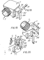
- the same reference numerals as were used in the earlier Figs. are used in Figs. 14, 15 and 16 to designate like parts, and no further description of Figs. 14, 15 and 16 will be given, other than to direct attention particularly to the form of the fuse holder 6 which, as is shown more clearly in Figs. 18,19 and 20, comprises a pivotally mounted portion 28 of a side wall of the plug body 1 formed with an internal web portion 29 (see Figs.
- a lever arm 33 is formed integrally with the side wall portion 28 to enable the same to be opened and closed manually.
- the lever arm 33 in its closed condition, makes a snap fit within a recess provided in the base of the plug body 1.
- An aperture 34 enables the fuse to be seen in its holder.
- the internal construction of the plug preferably is such that when the lever arm 33 is in its open condition, as shown in Fig.
- the connections of the live and neutral conductors of the cable to the live and neutral plug pins can be seen at least to the extent necessary to enable a visual check to be made that the correct conductor is connected to the correct plug pin.
- the lever arm 33 could be apertured to enable this check to be made even when the arm is in its closed condition; such apertures would not constitute any hazard since they would only be accessible to a user when the plug was unplugged, that is to say not plugged into a socket outlet.
- Fig. 21 illustrates a variation of the form of the plug designed to be aesthetically more pleasing.
- the recess in the plug body is inclined relative to the plug base and, as a result, the insert-driving component 10 is more readily available to be grasped and turned relative to the plug body 1.
- the component 10 furthermore is shown in Fig. 21 as being provided with a pair of opposed wings 40 (only one of which can be seen in Fig. 21) which enable the component to be grasped even more firmly.
- the component 40 could be made in two halves, which may be hingedly connected together, arranged to be snap locked around the cable; such a possibility would avoid the disadvantage which could arise sometimes that after assembly of the cable end to the insert preparatory to inserting the insert into the plug body, and with an appliance already connected to the other end of the cable, it was found that the insert driving component either had not been threaded onto the cable or had been threaded on the wrong way round.
- the insert and its cooperating recess in the plug body preferably are arranged such that the insert can be inserted into the recess only in a single orientation. This could readily be achieved by giving the insert and the recess a trapezoidal cross-section, for example, or by providing cooperating complementary formations on the two parts.
- a key is provided on the insert for engagement in a keyway formed in a surface of the recess; with such an arrangement the key on the insert could advantageously cooperate with the lever part of the fuse holder to obtain the desirable results that (a) the key lodges behind the fuse holder lever when the insert is driven fully home into the recess so that the lever acts as a physical bar against removal of the insert from the plug so long as the lever is in its closed condition, and (b) that the lever cannot be properly closed until the insert is driven fully home thereby preventing the plug from being plugged sufficiently far into the receptors of a socket outlet to make electrical connections between the plug pins and the socket outlet (it being recalled that only a small part of a plug pin at the tip thereof actually makes electrical contact with the corresponding socket outlet parts).
- the apertures 14 of the insert of the embodiment of Figs. 1 to 6 could be provided with means to enhance their grip on the insulation of a conductor received therein.
- the walls of the apertures could be provided with formations such as ribs or raised dimples to bite into and grip the cable insulation as the conductor is pulled tight in its respective aperture.
- the upper and/or lower rim(s) of the apertures could be slightly turned in and/or slightly serrated (particularly in the region of their narrower ends), and ribs could be provided on the inner walls of the apertures (again particularly at their narrower ends).
Landscapes
- Connector Housings Or Holding Contact Members (AREA)
- Details Of Connecting Devices For Male And Female Coupling (AREA)
Applications Claiming Priority (2)
| Application Number | Priority Date | Filing Date | Title |
|---|---|---|---|
| GB8410404 | 1984-04-24 | ||
| GB848410404A GB8410404D0 (en) | 1984-04-24 | 1984-04-24 | Electrical plugs |
Publications (2)
| Publication Number | Publication Date |
|---|---|
| EP0162597A2 true EP0162597A2 (fr) | 1985-11-27 |
| EP0162597A3 EP0162597A3 (fr) | 1987-05-13 |
Family
ID=10559969
Family Applications (1)
| Application Number | Title | Priority Date | Filing Date |
|---|---|---|---|
| EP85302871A Withdrawn EP0162597A3 (fr) | 1984-04-24 | 1985-04-24 | Fiche électrique domestique à assemblage aisé |
Country Status (2)
| Country | Link |
|---|---|
| EP (1) | EP0162597A3 (fr) |
| GB (2) | GB8410404D0 (fr) |
Cited By (3)
| Publication number | Priority date | Publication date | Assignee | Title |
|---|---|---|---|---|
| GB2204750A (en) * | 1987-04-13 | 1988-11-16 | Samuel Henry Alfred Lapidus | Improvements relating to electrical plugs |
| EP0345189A1 (fr) * | 1988-06-01 | 1989-12-06 | Société "S.E.D.B." SARL | Connecteur électrique |
| GB2308754A (en) * | 1995-12-29 | 1997-07-02 | Daewoo Electronics Co Ltd | Wire support for electrical plug |
Families Citing this family (7)
| Publication number | Priority date | Publication date | Assignee | Title |
|---|---|---|---|---|
| KR930004295Y1 (ko) * | 1990-12-06 | 1993-07-10 | 삼성전관 주식회사 | 편향 요크 |
| GB2263822A (en) * | 1992-01-14 | 1993-08-04 | Keith Edward Pemble | Connecting conductors to plugs. |
| GB2299461A (en) * | 1995-03-31 | 1996-10-02 | Caradon Mk Electric Ltd | Cord grip |
| FR2953334B1 (fr) * | 2009-11-27 | 2011-12-30 | Soc Ind De Construction Dappareils Et De Materiel Electriques | Dispositif de connexion electrique |
| CN102340065B (zh) * | 2010-07-16 | 2014-07-02 | 富士康(昆山)电脑接插件有限公司 | 插头连接器组件 |
| DE102014104449A1 (de) | 2014-03-28 | 2015-10-01 | Telegärtner Karl Gärtner GmbH | Elektrischer Steckverbinder |
| DE102014104446A1 (de) * | 2014-03-28 | 2015-10-01 | Telegärtner Karl Gärtner GmbH | Elektrischer Steckverbinder |
Family Cites Families (6)
| Publication number | Priority date | Publication date | Assignee | Title |
|---|---|---|---|---|
| GB288029A (en) * | 1927-04-01 | 1928-04-05 | George William Hawker | A new or improved electric lamp holder |
| NL158031B (nl) * | 1974-05-02 | 1978-09-15 | Steinmueller Kg Atlanta Kabel | Elektrische steker. |
| GB1604538A (en) * | 1978-05-30 | 1981-12-09 | Wood E | Electric lamp holders |
| GB2029650A (en) * | 1978-08-29 | 1980-03-19 | Pressac Ltd | Electrical connectors |
| WO1982000387A1 (fr) * | 1980-07-15 | 1982-02-04 | H Usher | Ameliorations relatives a des fiches electrioues |
| GB2120021B (en) * | 1982-04-28 | 1985-06-26 | Lee Hop | Electric plug |
-
1984
- 1984-04-24 GB GB848410404A patent/GB8410404D0/en active Pending
-
1985
- 1985-04-24 EP EP85302871A patent/EP0162597A3/fr not_active Withdrawn
- 1985-04-24 GB GB08510432A patent/GB2157900B/en not_active Expired
Cited By (8)
| Publication number | Priority date | Publication date | Assignee | Title |
|---|---|---|---|---|
| GB2204750A (en) * | 1987-04-13 | 1988-11-16 | Samuel Henry Alfred Lapidus | Improvements relating to electrical plugs |
| EP0287352A3 (fr) * | 1987-04-13 | 1990-04-04 | Lapidus, Samuel Henry Alfred | Fiches électriques |
| GB2204750B (en) * | 1987-04-13 | 1991-06-19 | Samuel Henry Alfred Lapidus | Improvements relating to electrical plugs |
| EP0345189A1 (fr) * | 1988-06-01 | 1989-12-06 | Société "S.E.D.B." SARL | Connecteur électrique |
| FR2632458A1 (fr) * | 1988-06-01 | 1989-12-08 | Borloz Didier | Connecteur electrique |
| GB2308754A (en) * | 1995-12-29 | 1997-07-02 | Daewoo Electronics Co Ltd | Wire support for electrical plug |
| US5833489A (en) * | 1995-12-29 | 1998-11-10 | Daewoo Electronics Co., Ltd. | Electrical plug |
| GB2308754B (en) * | 1995-12-29 | 2000-02-02 | Daewoo Electronics Co Ltd | Electrical plug |
Also Published As
| Publication number | Publication date |
|---|---|
| GB2157900A (en) | 1985-10-30 |
| GB8410404D0 (en) | 1984-05-31 |
| GB8510432D0 (en) | 1985-05-30 |
| EP0162597A3 (fr) | 1987-05-13 |
| GB2157900B (en) | 1988-05-11 |
Similar Documents
| Publication | Publication Date | Title |
|---|---|---|
| US4183603A (en) | Extension cord lock | |
| US4834677A (en) | Male and/or female electrical connectors | |
| US4148540A (en) | Electrical coupling devices | |
| US5393243A (en) | Releasable cord connecting lock | |
| US3543218A (en) | Safety connectors for electrical extension cords | |
| EP0162597A2 (fr) | Fiche électrique domestique à assemblage aisé | |
| AU743965B2 (en) | Electrical connector | |
| WO2000001971A9 (fr) | Pince pour cordon d'alimentation electrique | |
| US5839911A (en) | Adjustable and releasable strain relief | |
| US3163481A (en) | Clasp for holding an attachment plug to an electrical outlet | |
| JP4567209B2 (ja) | 胎児頭皮電極等の特に医学的な使い捨て用品のための電気的な圧接コンタクト | |
| US5782648A (en) | Electrical plug attachment system | |
| US3861771A (en) | Cable connector with five point grip and non-twist, non-pullout function and with ratchet latch | |
| US4125312A (en) | Connector for electrical apparatus | |
| US5453024A (en) | Two-pin electric plug, to be wired without unsheathing the lead | |
| US1956018A (en) | Electric safety plug | |
| US4342497A (en) | Battery terminal connector | |
| US6319044B1 (en) | Cord lock | |
| US6358103B1 (en) | No-crimp electrical connector side-by-side type | |
| US2810115A (en) | Connectors for lamp cords | |
| US2923909A (en) | modrey | |
| EP0353539A1 (fr) | Connecteur pour câbles électriques à fiche et douille volantes | |
| US2128883A (en) | Electrical plug | |
| US4834571A (en) | Universal wire lock | |
| EP0063120B1 (fr) | Ameliorations relatives a des fiches electriques |
Legal Events
| Date | Code | Title | Description |
|---|---|---|---|
| PUAI | Public reference made under article 153(3) epc to a published international application that has entered the european phase |
Free format text: ORIGINAL CODE: 0009012 |
|
| AK | Designated contracting states |
Designated state(s): AT BE CH DE FR GB IT LI LU NL SE |
|
| PUAL | Search report despatched |
Free format text: ORIGINAL CODE: 0009013 |
|
| AK | Designated contracting states |
Kind code of ref document: A3 Designated state(s): AT BE CH DE FR GB IT LI LU NL SE |
|
| 17P | Request for examination filed |
Effective date: 19871112 |
|
| 17Q | First examination report despatched |
Effective date: 19891110 |
|
| STAA | Information on the status of an ep patent application or granted ep patent |
Free format text: STATUS: THE APPLICATION IS DEEMED TO BE WITHDRAWN |
|
| 18D | Application deemed to be withdrawn |
Effective date: 19931103 |
|
| RIN1 | Information on inventor provided before grant (corrected) |
Inventor name: KING, TERENCE E. |