EP0162652A2 - Système, appareil et méthode de détection et de réglage du pompage dans un turbocompresseur - Google Patents
Système, appareil et méthode de détection et de réglage du pompage dans un turbocompresseur Download PDFInfo
- Publication number
- EP0162652A2 EP0162652A2 EP85303388A EP85303388A EP0162652A2 EP 0162652 A2 EP0162652 A2 EP 0162652A2 EP 85303388 A EP85303388 A EP 85303388A EP 85303388 A EP85303388 A EP 85303388A EP 0162652 A2 EP0162652 A2 EP 0162652A2
- Authority
- EP
- European Patent Office
- Prior art keywords
- surge
- signal
- compressor
- surges
- duration
- Prior art date
- Legal status (The legal status is an assumption and is not a legal conclusion. Google has not performed a legal analysis and makes no representation as to the accuracy of the status listed.)
- Granted
Links
Images


Classifications
-
- F—MECHANICAL ENGINEERING; LIGHTING; HEATING; WEAPONS; BLASTING
- F04—POSITIVE - DISPLACEMENT MACHINES FOR LIQUIDS; PUMPS FOR LIQUIDS OR ELASTIC FLUIDS
- F04D—NON-POSITIVE-DISPLACEMENT PUMPS
- F04D27/00—Control, e.g. regulation, of pumps, pumping installations or pumping systems specially adapted for elastic fluids
- F04D27/001—Testing thereof; Determination or simulation of flow characteristics; Stall or surge detection, e.g. condition monitoring
-
- F—MECHANICAL ENGINEERING; LIGHTING; HEATING; WEAPONS; BLASTING
- F04—POSITIVE - DISPLACEMENT MACHINES FOR LIQUIDS; PUMPS FOR LIQUIDS OR ELASTIC FLUIDS
- F04D—NON-POSITIVE-DISPLACEMENT PUMPS
- F04D27/00—Control, e.g. regulation, of pumps, pumping installations or pumping systems specially adapted for elastic fluids
- F04D27/02—Surge control
- F04D27/0292—Stop safety or alarm devices, e.g. stop-and-go control; Disposition of check-valves
-
- G—PHYSICS
- G01—MEASURING; TESTING
- G01K—MEASURING TEMPERATURE; MEASURING QUANTITY OF HEAT; THERMALLY-SENSITIVE ELEMENTS NOT OTHERWISE PROVIDED FOR
- G01K3/00—Thermometers giving results other than momentary value of temperature
- G01K3/08—Thermometers giving results other than momentary value of temperature giving differences of values; giving differentiated values
- G01K3/10—Thermometers giving results other than momentary value of temperature giving differences of values; giving differentiated values in respect of time, e.g. reacting only to a quick change of temperature
-
- G—PHYSICS
- G05—CONTROLLING; REGULATING
- G05D—SYSTEMS FOR CONTROLLING OR REGULATING NON-ELECTRIC VARIABLES
- G05D23/00—Control of temperature
- G05D23/19—Control of temperature characterised by the use of electric means
- G05D23/1927—Control of temperature characterised by the use of electric means using a plurality of sensors
- G05D23/1928—Control of temperature characterised by the use of electric means using a plurality of sensors sensing the temperature of one space
-
- G—PHYSICS
- G05—CONTROLLING; REGULATING
- G05D—SYSTEMS FOR CONTROLLING OR REGULATING NON-ELECTRIC VARIABLES
- G05D23/00—Control of temperature
- G05D23/19—Control of temperature characterised by the use of electric means
- G05D23/20—Control of temperature characterised by the use of electric means with sensing elements having variation of electric or magnetic properties with change of temperature
- G05D23/22—Control of temperature characterised by the use of electric means with sensing elements having variation of electric or magnetic properties with change of temperature the sensing element being a thermocouple
Definitions
- the present invention relates generally to detecting surges that occur in rotating compressors and, more particularly, for a method and means to quickly detect surge and generate control signals which are used to prevent serious compressor damage caused by excessive surging by providing warnings and control actions before the individual and cumulative stresses of repetative surge cycles damage the compressor.
- Turbo compressors are used to deliver compressed gas into many and varying type processes. These processes impose a resistance to flow.
- the resistance may be relatively constant, or it may vary considerably during normal or abnormal process operation.
- An increase in process resistance causes an increase in the compressor discharge pressure. If the resistance becomes excessive, a point is reached where the compressor is not capable of producing the necessary discharge pressure and a momentary flow reversal occurs. This flow reversal is called "surge”. It can cause serious compressor damage due to induced vibratory stresses and very high temperatures.
- surge the discharge gas is hot due to the compression process. When surge occurs the hot gas flows back through the compressor causing the inlet temperature to increase.
- the main protection against surging is the use of an antisurge control mechanism which, at some limiting point prior to surge, opens bypass valves to vent the compressor discharge to the atmosphere to keep the rate of fluid flow in the compressor at some admissable value.
- a surge detection system as in this invention, may be used as a backup in case the main protection system fails to prevent surge.
- Various methods of surge detection were used in the prior art.
- a single temperature sensor such as a thermocouple is located at the compressor intake to detect the sudden temperature rise which accompanies the surge.
- the system must be set to operate higher than the highest normal operating temperature in order to detect the abnormal temperature rise. For example, a 650 C set point would be typical for a maximum normal operating temperature of 38°C.
- the time to detect surge increases as the operating temperature decreases. For example, an increase of 82°C would be needed to activate the surge detector when the compressor is operating at -17°C Such a system would have failed to count medium and mild surges because the change in temperature was less than 82°C.
- the system herein described provides faster and more reliable surge detection and responds to all surges which cause greater than a 27.8 °C increase in temperature regardless of the operating temperature at which the surge occurs. Also, the system response is extremely fast and reacts to start corrective action less than 4 of a second after the onset of a surge. Further, set points at which signals are developed representing magnitude of surge are not rate-of-change dependent and thus surge tests are not necessary. Also, no automatic controls are required to disable the surge detection system when the compressor is shut down because the heat soaking is not fast enough to produce a change in temperature alarm required by the present system. Further, it provides a warning signal or compressor shut-down based upon the number, intensity and duration of the surges, not just the number of them.
- the present invention utilizes two temperature sensors located in the compressor inlet such that both sensors are subject to the common gas inlet temperature.
- One of the sensors has a rapid response, Tf, to temperature change and the other sensor has a slow response, Ts, to temperature change in comparison with the first sensor rapid response.
- These sensors which are preferably the junctions of a thermocouple, are connected electrically in opposed relationship thereby producing a signal output, Tf-Ts, for a given change in temperature.
- Tf-Ts signal output
- a differential signal is produced in proportion to the temperature change whereby the differential signal may be used to detect the number, magnitude and duration of the surges which are occurring.
- the signal Tf + Ts could be used to indicate a rapid change in termperature. If so, the signal levels would have to change in the control circuitry.
- a surge detection system for a compressor having a gas inlet and a gas outlet and experiencing rapid temperature changes in said gas inlet during surges said detection system comprising:
- a surge detection system as in claim 1 wherein said converting means includes:
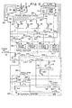
- FIG. is a diagrammatic representation of a rotary turbo compressor such as, for example only, an axial flow compressor, which utilizes an embodiment of surge detection system according to the present invention.
- a drive source 10 which could be any type of electrical or fuel driven motor, provides power to and rotates compressor 12 through a coupling means 14 such as a drive shaft.
- Compressor 12 has a gas inlet 16 and a discharge port or gas outlet 18 which is coupled to some device 20 for operating a process of any sort which could use the output of compressor 12.
- compressors are designed to operate under certain well defined stable flow conditions. When the flow becomes unstable due to a flow interruption in the system, compressors will surge. Compressor surge may be defined as a large amplitude, low frequency oscillation of the total annulus-averaged flow through the compressor. It is also well known in the art that each time a compressor surges the compressor blades and bearings are subjected to very high stresses. Excessive surging may eventually weaken the compressor blades to a point that de-blading is possible. Thus, serious compressor damage can be caused by excessive surging. The potentially damaging effect cannot be precisely measured but is a function of the number, magnitude and duration of the surge cycles. Control actions that take place in the present invention are based on these three parameters.
- an anti-surge control device 22 which regulates a valve 23 to recycle part or all of the gas back to the compressor inlet, or vent it to atmosphere as would be done for an air compressor.
- anti-surge controls and related system compo-. nents are subject to malfunctions which, in turn, can result in serious compressor damage if too many surge cycles occur.
- redundancy for the anti-surge control device 22 is needed to protect the machine from short-term damage due to sustained surging and to provide a warning when maintenance is needed to prevent serious damage due to the cumulative effects of occasional surges over a relatively long'period of time.
- thermocouples 24 and 26 are mounted in the gas inlet 16 of compressor 12 where both are subjected to the same temperature.
- one of the thermocouples 26 is of special design and responds very quickly to any temperature change.
- the other thermocouple 24 is of a standard design and has a relatively slow response to temperature change as compared to the first thermocouple 26.
- thermocouple 24 reacts more slowly to a temperature change is because it is encased in a thermowell 29 as shown in FIG. 2 which prevents the heat from reaching the thermocouple element itself quickly.
- thermocouple 24 is a slow response (Ts) thermocouple while thermocouple 26 is a fast response (Tf) thermocouple.
- Ts slow response
- Tf fast response
- the time constant of the fast thermocouple 26 may be equal to or less than .3 second while the time constant of the slow thermocouple 24 may be greater than one minute.
- the fast thermocouple 26 is made of chromel constantan, type E, 30 gauge wire as manufactured by Omega Engineering Inc. While the slow thermocouple 24 is made of the same type wire except it is 18 gauge.
- thermowell 29 is a tapered shank, 1/4 inch nominal bore sleeve made of 304 stainless steel manufactured by Ashcroft.
- These thermocouples 26 and 28 are coupled in opposing electrical relationship as shown in FIG. 2 thereby producing a differential signal level output for a given change in compressor inlet temperature. Since these thermocouples are mounted in the compressor inlet 16 such that both thermocouples 26 and 28 are subject to the same or common temperature change, and since one of the thermocouples responds to that temperature change faster than the other, a differential electrical signal (delta-t) is produced by the thermocouples when a surge occurs because of the rapid temperature rise in the inlet nozzle 16 of compressor 12.
- Table I illustrates the relationship of the temperature detected by the fast responding (Tf) thermocouple 26, the temperature detcted by the slow responding (Ts) thermocouple 24, the delta-t, (Tf-Ts), for a given operating ambient temperature of 50° F, and the millivolt signal generated by each of the thermocouple circuits and, since the thermocouples are electrically connected in opposition to each other, the algebraically summed output millivolts (Tf-Ts), and the event represented by each of these conditions. It should be noted that the values given in Table I are with the slow thermocouple (Ts) at the ambient temperature of 50° F. Due to thermocouple nonlinearity, actual delta-t values will vary approximately plus or minus five degrees over the average range of ambient operating temperatures.
- thermocouple The first event represented in Table I is a broken thermocouple. This condition could also occur momentarily during a cold weather start-up of a warm compressor. Prior to start-up, the delta-t indication would be approximately zero since both the fast thermocouple 26 and the slow thermocouple 24 would be at the same temperature of 50° F. The delta-t would then drop rapidly as the compressor begins taking in cold outside air or gas. This could cause, for instance, a delta-t of -50 degrees. This same electrical indication would exist if either thermocouple breaks because the instrument is designed to drive down scale if the thermocouple input circuit is disconnected.
- the delta-t would be 50° F and the difference in the millivolts generated by the fast responding thermocouple 26 as compared to the slow responding thermocouple 24 would be 1.8 millivolts and that signal would represent a mild surge.
- the delta-t would be 400° F and the difference in millivolts generated by the fast thermocouple 26 and the slow responding thermocouple 24 would be 15.3 millivolts which would represent a major surge taking place in the compressor.
- This unit is a millivolt-to-current converter which receives the millivolt input from the thermocouples 24 and 26 and produces a substantially linear current output as illustrated in FIG 3. It is comprised of a unit 32A designated as the TC2000A-54 which is manufactured by D ynalco Corporation and which has two set points or signal levels that are adjustable in conjunction with a companion unit 32B designated as TR2249 which is also manufactured by Dynalco and which has two adjustable set points thus giving a total of four adjustable level outputs. As can be seen in the graph in FIG.
- differential surge detector 32 will produce an analog signal on line 34 covering the range of 4-20 ma. which may be used for producing a chart or to otherwise make a permanent record of the differential temperatures occuring in the inlet manifold 16 of compressor 12.
- the signal output on line 36 may represent a major, medium or minor surge. This occurs for a minor surge by having a 7.2 milliamp signal threshold level set in detector 32 by a comparator and when the input signal from thermocouples 24 and 26 causes a signal to be produced by detector 32 that equals or exceeds that comparator threshold level, an output signal is produced on line 36 representing a minor surge.
- a second signal threshold level is set, as for instance at 12.0 milliamps by a comparator
- an output would be produced on line 38 when a major or medium surge occurs in compressor 12.
- a third signal threshold level were set by a comparator at 19.2 milliamps, an output signal would be produced on line 40 when a major surge occurs in compressor 12.
- a fourth signal threshold level is set by a comparator at 4 milliamps or less, a signal would be produced on line 42 indicating a broken or open thermocouple circuit. In such case the output of the surge detector 32 is driven downwards to 4 ma.
- Each of the signals on lines 34, 36, 38, 40 and 42 can be used in whatever manner desired to indicate and control surge conditions and to insure proper maintenance of the compressor 12 that is being subjected to the surges.
- thermocouples 24 and 26 are mounted in the compressor 12 inlet nozzle 17.
- the signal thermocouple 26 has a very fast response time and as identified "Tf”.
- the reference thermocouple 24 has a very slow response time and is referred to as "Ts”.
- the signal thermocouple (Tf) has an exposed tip of very small diameter wire.
- the reference thermocouple (Ts) has an enclosed tip of large diameter wire and is installed in a thermowell which makes its response even slower. During a surge cycle, the compressor inlet temperature rises and falls very rapidly (1-4 seconds typical). Output from the fast thermocouple 26 (Tf) increases rapidly in response to the temperature increase, but the slow thermocouple 24 (Ts) output changes ⁇ hardl ⁇ at all in the short time interval.
- thermocouples are wired with opposing polarity and therefore the rapid temperature rise appears momentarily as a differential temperature (Tf-Ts) signal.
- a differential temperature detector 32 produces analog and other output signals which are used .for visual indication, surge control and compressor shut down.
- a delta-t indicator 44 which can be a recorder or other indicator to preserve a record of the difference in temperature occurring between the thermocouple 26 having the fast response and the thermocouple 24 having the slow response.
- the surge detection circuit 46 After it receives the signals on line 36 representing all surges taking place in the compressor, the signals on line 38 representing the medium and major surges taking place in the compressor 12, the signals on line 40 representing the major surges taking place in compressor 12, and the signals on line 42 representing a broken thermocouple, the surge detection circuit 46 generates a plurality of output signals. One of these signals on line 48 is generated when a signal representing all surges appears on line 36. The surge detection circuit 46 couples the signal on line 48 to driver 10 for causing the compressor 12 to shut down whenever any surge is detected.
- the driver 10 can be deactivated, of course, in any well known means as for instance shutting off the power supply or opening the electrical circuit which is powering the driving means 10.
- Surge counters 56 receive the signals from surge detection circuit 46 on lines 50, 52 and 54 and provide a separate counter for receiving the signals on each of those lines thus counting the total number of surges occurring as indicated by the signals on line 50, counting the number of medium and minor surges according to the signals appearing on line 52, and counting the number of major surges according to the signals appearing on line 54.
- a signal appears on line 50 representing all surges, that signal is also coupled through line 57 to an oscillator circuit 58.
- the oscillator circuit is activated during the duration of the signal representing any surge and thereby generates a plurality of pulses which represents the duration and/or magnitude of each of the surges.
- These pulses are connected through coupling means 59 to a decremental counter 60 which establishes a maximum threshold of surge duration for a compressor by setting the decrementing counter 60 to a predetermined count whereby the pulses from oscillating circuit 58 decrement counter 60 thus maintaining a cumulative record of the duration, number, and magnitude of the surges being detected by oscillator circuit 58.
- decremental counter 60 Assume that a maximum of 75 pulses represents the maximum accumulation of surge stress allowed for compressor 12. This count of 75 is set in decremental counter 60. As each surge is detected by oscillator circuit 58 and pulses are produced according to number, magnitude and duration of the surges, the decremental counter is counting down until 75 pulses have been counted. At that time, the decremental counter 60 produces an output on line 64 which is coupled to an alarm annunciator 62 and/or the compressor shutdown circuits in driver 10 through line 48.
- control action and pulse counting is based on the three parameters of number, intensity and duration of said surges. Therefore, the system protects the compressor from short term damage due to intense surging and yet provides a warning when maintenance is needed to prevent serious damage due to the cumulative effects of occasional minor surges over a relatively long period of time.
- each surge which produces a delta-t greater than 50° F is counted.
- each surge subtracts at least one count from decremental counter 60. The number of counts subtracted from decremental counter 60 for each surge varies depending upon the surge intensity and duration. One count may be removed for a mild surge, but more counts for a larger surge.
- two or three counts might be subtracted for a surge of medium intensity and four or five counts for a major surge.
- the decremental counter decreases to 0, it produces an output signal to warn of maximum danger due to excessive cumulative surging and, if desired, may shut down the compressor.
- the alarm annunciator 62 generates the warning signal.
- Surge detection circuit 46 may also produce an output signal on line 66 which is coupled to the alarm annunciator 62 to cause an alarm each time a broken thermocouple signal is generated on line 42.
- the warning alerts the personnel that there is a problem with the thermocouples and they need to be checked.
- surge detector 46 may produce a signal on line 68 each time a surge signal is generated on line 36 thereby opening control valve 70 to vent the compressor to the atmosphere thus controlling the surge that is taking place at any time.
- FIG. 5 The details of the novel circuit are illustrated in FIG. 5.
- thermocouples 24 and 26 are mounted in the compressor 12 gas inlet 16 so that both thermocouples are subjected to the same temperature environment.
- the thermocouples 24 and 26 have a different time constant in response to temperature.
- the slow acting thermocouple has a time constant greater than one minute while the fast acting thermocouple has a time constant equal to or less than .3 second.
- the thermocouple outputs are coupled electrically in opposing relationship so that when the thermocouples are experiencing the same ambient temperature, the output from them is 0.
- the 4 milliamp output represents a -50° F differential temperature (Tf-Ts) being produced by thermocouples 24 and 26
- the 7.2 milliamp output represents a +50° F differential temperature (Tf-Ts) between thermocouples 24 and 26
- a 12 milliamp output represents a 200° F temperature differential (Tf-Ts) between thermocouples 24 and 26
- a 19.2 milliamp output represents a 400° F temperature differential (Tf-Ts) between thermocouples 24 and 26.
- Those output levels are used to operate a surge detection circuit 46.
- the entire range of 4 to 20 milliamps DC may appear on line 34 as an analog signal which is coupled to delta-t meter 44 which records the difference in temperature occurring between the two thermocouples. This makes a permanent record of the operation available.
- the 4 milliamp signal causes a signal to appear on line 42 which is coupled to relay 72 to de-energize it and cause its switch contact 74 to return to its normally closed position.
- the power switch 76 is activated and electrical power is available, that power is coupled through normally closed switch contact 74 and line 66 to an annunciator 62 to indicate that a broken thermocouple exists.
- this alarm condition being generated by annunciator 62 could also occur momentarily during a cold weather start up of a warm compressor. In that case, the delta-t indication would be approximately 0 prior to start up and would then drop rapidly as the compressor starts taking in cold outside air or gas.
- the differential temperature (Tf-Ts) may become a -50° F and if that occurs a signal would be caused to appear on line 42 from surge detector 32 to de-energize relay 72 and return its normally closed switch contact 74 to its closed position thus coupling power to the annunciator which would give a warning. If this occurs, several minutes should be allowed to pass so the delta-t indication may increase somewhat above the ⁇ 50° F differential temperature and then the alarm could be reset in any well known manner.
- surge detector 32 receives a +50° F temperature differential from thermocouples 24 and 26, it causes an output signal to be produced on line 36 representing 7.2 milliamps which de-energizes relay 76 and causes a first switch contact 78 to return to its normally closed position to couple power on line 50 to a minor surge counter 80.
- counter 80 records that surge because de-energized relay 76 closes contact 78.
- counter 80 keeps track of the total number of surges occurring.
- thermocouples 24 and 26 develop a differential temperature of 200° F
- the 12 milliamp signal causes a signal to be generated on line 38 thus de-energizing relay coil 82.
- coil 82 When coil 82 is de-energized, it returns its switch 84 to its normally closed position which couples power on line 52 to medium surge counter 86. This means that although that same surge was counted by the minor surge counter 80, the medium surge is also counted on medium surge counter 86.
- thermocouples 24 and 26 produce a temperature differential of 400° F
- the 19.2 milliamps signal developed by surge detector 32 on line 40 causes relay 88 to be de-energized which returns its contact 90 to its normally closed position and couples a signal on line 54 to major surge counter 92.
- the medium surge counter 86 will also be activated by a major surge.
- minor surge counter 80 records all surges
- medium surge counter 86 records both major and medium surges
- major surge counter 92 records only the number of major surges.
- minor surge 80 recorded 50 surges
- medium surge counter 86 recorded 10 surges
- major surge counter 92 recorded 2 surges, that would indicate that 2 major surges occurred, 8 medium surges occurred and 40 minor surges occurred.
- relays 72, 76, 82 and 88 have normally closed contacts. Thus, the respective contacts are held in the open position until a signal dictates that a particular relay be de-energized to close its contact. In this way, any broken wires would de-energize an affected relay and cause a warning signal to be generated.
- the compressor 12 has associated with it anti-surge controls 22 which can open valves 23 (in FIG. 1) to vent the compressor discharge to the atmosphere in an effort to control surges, it is not unknown for these anti-surge controls to malfunction. In that event, serious harm could come to the compressor if the surge isn't alleviated. For that reason, if desired, a second contact 94 may be coupled to relay coil 76 so that each time a surge occurs and relay coil 76 is de-energized, contact 94 would return to its normally closed position thus coupling power to anti-surge valve 70 which would cause the output of compressor 22 to be vented to the atmosphere and to shut down control 98 thereby protecting the compressor 12.
- the anti- surge control system 22 is made redundant by this backup system.
- the potentially damaging effect to a compressor caused by surge cannot be precisely measured but it is a function of the number, magnitude and duration of surge cycles in combination.
- the compressor may be sufficiently damaged that it ought to be inspected and/or parts replaced.
- a few surges of major intensity may cause as much or more damage than many surges of minor intensity.
- a few surges having a long duration may be considerably more damaging than many medium or minor surges of shorter duration.
- the time duration of the surge is also important to consider.
- the present system protects the compressor from short term damage due to intense or surging and yet provides warning when maintenance is needed to prevent serious damage due to the cumulative effects of occasional surges over a relatively long period of time.
- the stress measurement circuitry comprises an oscillator circuit 58 and a decremental counter circuit 60.
- the power switch 76 When the power switch 76 is first activated, power is coupled to the upper portion of the circuit in FIG. 4 immediately but is coupled to the stress measurement circuitry 58 and 60 through the action of relay coil 100 which has a second delay-before switch 102 closes. This gives time for all of the signal generating circuits in the upper portion of FIG. 5 to stabilize before the measurement circuit is coupled to them.
- switch 57 is also a contact which is operated by relay coil 76.
- switch 57 closes supplying power through normally closed switch 112 to relay coil 114 thus activating coil 114.
- relay coil 114 When relay coil 114 is energized, it closes normally open switch 116 thus coupling power on line 118 to relay 120 thus energizing relay 120.
- relay 120 When relay 120 is energized it opens switch 112 thus removing the power from relay 114.
- relay 114 is de-energized it opens switch 116 which de-energizes relay 120.
- relays 114 and 120 form a multivibrator by alternately opening and closing switches 112 and 116 so long as switch 57 is in the closed position caused by relay coil 76.
- This relay 76 thus accounts for both intensity and duration of a surge. In other words, if a small surge or minor surge de-energizes relay 76 and closes contact 57, if that minor surge is of extended duration, the oscillator circuit 58 will produce a series of output pulses by relay 114 alternately opening and closing another switch contact 59.
- the opening and closing of contact 59 decrements counter 122 which has a predetermined count stored therein.
- relay coil 76 also closes switch contact 57 and because the surge is a major one it will last for a greater length of time than the normal minor surge and thus oscillator circuit 58 will produce several pulses by opening and closing switch 59 to decrement counter 122.
- the oscillator circuit 58 produces more or less pulses depending upon either the magnitude or duration of the surge thereby taking into account both magnitude and duration of each surge.
- decremental counter relay 122 When decremental counter relay 122 has counted 75 counts, it closes normally open contact 124 which couples the power supply to relay coil 126 to energize it. When relay 126 is energized, it closes contact 64 which couples power on line 128 to annunciator 62 as well as to the compressor shutdown circuit 98.
- an output signal is generated to warn of maximum danger due to excessive surging and the compressor is shut down.
- the warning indicates that maintenance is needed to prevent serious damage to the compressor due to the cumulative effects of occasional surges over a relatively long period of time. Therefore, by varying the number of counts being decremented from counter 122 based on the number of surges, the surge intensity and the duration of the surge, the warning signal produced by the closing of switch 64 of relay 126 more truly represents the potential for surge induced blade failure than if only one count was subtracted for each surge regardless of its intensity or duration.
- relay 126 when relay 126 is energized, it closes switch contact 130 which couples power to a reset switch 132. After the proper maintenance has been performed and it is desired to start the compressor again, reset button 132 is depressed thus coupling power to reset coil 134 which resets decremental counter 122 to the 75 count and opens the switch contact 124. At the same time, it continues to maintain power on relay 126 even though contact 124 has now opened.
- reset button 132 is released, the power is removed from relay coil 126 which opens contacts 64 and 130 thus removing the signal to annunciator 62 and the computer shutdown circuit 98 and also removing the power from the push button switch 132. The unit is thus reset and ready to begin operation anew.
- thermocouples having different temperature response times mounted in a common area in the air intake section of the compressor whereby a sudden change in temperature which accompanies a surge causes a differential voltage to be produced by the thermocouples and this voltage is used to develop threshold levels to recognize minor, medium and major surges, as well as a warning when the thermocouple circuit is broken.
- the novel circuit also includes circuitry for generating counts based on surge intensity, magnitude and number to warn of surge induced blade failure potential after a predetermined number of counts have been generated.
Landscapes
- Engineering & Computer Science (AREA)
- Physics & Mathematics (AREA)
- General Physics & Mathematics (AREA)
- Mechanical Engineering (AREA)
- General Engineering & Computer Science (AREA)
- Automation & Control Theory (AREA)
- Control Of Positive-Displacement Air Blowers (AREA)
Applications Claiming Priority (4)
| Application Number | Priority Date | Filing Date | Title |
|---|---|---|---|
| US06/609,705 US4594051A (en) | 1984-05-14 | 1984-05-14 | System, apparatus, and method for detecting and controlling surge in a turbo compressor |
| US609703 | 1984-05-14 | ||
| US06/609,703 US4594050A (en) | 1984-05-14 | 1984-05-14 | Apparatus and method for detecting surge in a turbo compressor |
| US609705 | 1984-05-14 |
Publications (3)
| Publication Number | Publication Date |
|---|---|
| EP0162652A2 true EP0162652A2 (fr) | 1985-11-27 |
| EP0162652A3 EP0162652A3 (en) | 1987-06-03 |
| EP0162652B1 EP0162652B1 (fr) | 1991-05-15 |
Family
ID=27086097
Family Applications (1)
| Application Number | Title | Priority Date | Filing Date |
|---|---|---|---|
| EP85303388A Expired - Lifetime EP0162652B1 (fr) | 1984-05-14 | 1985-05-14 | Système, appareil et méthode de détection et de réglage du pompage dans un turbocompresseur |
Country Status (2)
| Country | Link |
|---|---|
| EP (1) | EP0162652B1 (fr) |
| DE (1) | DE3582821D1 (fr) |
Cited By (9)
| Publication number | Priority date | Publication date | Assignee | Title |
|---|---|---|---|---|
| DE3540088A1 (de) * | 1985-11-12 | 1987-05-14 | Gutehoffnungshuette Man | Verfahren zur erfassung von pumpstoessen an turbokompressoren |
| EP0732507A3 (fr) * | 1992-04-10 | 1998-07-08 | Ingersoll-Rand Company | Méthode et appareil pour détecter et prévenir le pompage dans un compresseur centrifugal |
| WO2008021632A3 (fr) * | 2006-08-15 | 2008-04-24 | Gen Electric | Systèmes de turbocompresseur et procédés pour commander ceux-ci |
| CN104005975A (zh) * | 2014-05-20 | 2014-08-27 | 北京工业大学 | 一种轴流式通风机失速和喘振的诊断方法 |
| CN105604973A (zh) * | 2015-12-18 | 2016-05-25 | 成都成发科能动力工程有限公司 | 一种轴流压缩机全线防喘振控制方法 |
| US10048104B2 (en) | 2012-11-21 | 2018-08-14 | Dynapar Corporation | Sensor and/or power harvesting apparatus having a wide dynamic range for responding to a driving rotational input |
| CN112628169A (zh) * | 2020-12-08 | 2021-04-09 | 中国工程物理研究院材料研究所 | 一种核设施通风机在线状态监测及故障预警系统 |
| CN115324746A (zh) * | 2022-08-15 | 2022-11-11 | 中国航发沈阳发动机研究所 | 一种航空发动机防止持续误判喘振的控制方法及装置 |
| CN116221191A (zh) * | 2023-05-06 | 2023-06-06 | 西门子能源有限公司 | 流体压缩系统和控制流体压缩系统的方法 |
Families Citing this family (1)
| Publication number | Priority date | Publication date | Assignee | Title |
|---|---|---|---|---|
| EP3332225B1 (fr) | 2015-08-07 | 2020-10-28 | Brewer Science, Inc. | Système de capteur environnemental et processeur de signal |
Family Cites Families (8)
| Publication number | Priority date | Publication date | Assignee | Title |
|---|---|---|---|---|
| US2926524A (en) * | 1956-01-12 | 1960-03-01 | John C Sanders | Method and mechanism for detecting stall and surge of gas engines |
| US2955745A (en) * | 1956-12-17 | 1960-10-11 | Fairchild Engine & Airplane | Temperature responsive surge control |
| US3341121A (en) * | 1965-01-13 | 1967-09-12 | Johnson Service Co | Condition responsive control circuit and apparatus therefor |
| US3369750A (en) * | 1965-09-03 | 1968-02-20 | Leeds & Northrup Co | Electrical control network |
| US4061116A (en) * | 1974-10-17 | 1977-12-06 | Nissan Motor Co., Ltd. | Knock level control apparatus for an internal combustion engine |
| US4060979A (en) * | 1975-11-19 | 1977-12-06 | United Technologies Corporation | Stall warning detector for gas turbine engine |
| US4046490A (en) * | 1975-12-01 | 1977-09-06 | Compressor Controls Corporation | Method and apparatus for antisurge protection of a dynamic compressor |
| US4399548A (en) * | 1981-04-13 | 1983-08-16 | Castleberry Kimberly N | Compressor surge counter |
-
1985
- 1985-05-14 EP EP85303388A patent/EP0162652B1/fr not_active Expired - Lifetime
- 1985-05-14 DE DE8585303388T patent/DE3582821D1/de not_active Expired - Fee Related
Cited By (11)
| Publication number | Priority date | Publication date | Assignee | Title |
|---|---|---|---|---|
| DE3540088A1 (de) * | 1985-11-12 | 1987-05-14 | Gutehoffnungshuette Man | Verfahren zur erfassung von pumpstoessen an turbokompressoren |
| EP0222383B1 (fr) * | 1985-11-12 | 1990-10-24 | MAN Gutehoffnungshütte Aktiengesellschaft | Procédé d'enregistrement des à-coups de pompage à des turbocompresseurs |
| EP0732507A3 (fr) * | 1992-04-10 | 1998-07-08 | Ingersoll-Rand Company | Méthode et appareil pour détecter et prévenir le pompage dans un compresseur centrifugal |
| WO2008021632A3 (fr) * | 2006-08-15 | 2008-04-24 | Gen Electric | Systèmes de turbocompresseur et procédés pour commander ceux-ci |
| CN101506528B (zh) * | 2006-08-15 | 2013-06-05 | 通用电气公司 | 涡轮增压器系统和用于操作该涡轮增压器系统的方法 |
| US10048104B2 (en) | 2012-11-21 | 2018-08-14 | Dynapar Corporation | Sensor and/or power harvesting apparatus having a wide dynamic range for responding to a driving rotational input |
| CN104005975A (zh) * | 2014-05-20 | 2014-08-27 | 北京工业大学 | 一种轴流式通风机失速和喘振的诊断方法 |
| CN105604973A (zh) * | 2015-12-18 | 2016-05-25 | 成都成发科能动力工程有限公司 | 一种轴流压缩机全线防喘振控制方法 |
| CN112628169A (zh) * | 2020-12-08 | 2021-04-09 | 中国工程物理研究院材料研究所 | 一种核设施通风机在线状态监测及故障预警系统 |
| CN115324746A (zh) * | 2022-08-15 | 2022-11-11 | 中国航发沈阳发动机研究所 | 一种航空发动机防止持续误判喘振的控制方法及装置 |
| CN116221191A (zh) * | 2023-05-06 | 2023-06-06 | 西门子能源有限公司 | 流体压缩系统和控制流体压缩系统的方法 |
Also Published As
| Publication number | Publication date |
|---|---|
| DE3582821D1 (de) | 1991-06-20 |
| EP0162652A3 (en) | 1987-06-03 |
| EP0162652B1 (fr) | 1991-05-15 |
Similar Documents
| Publication | Publication Date | Title |
|---|---|---|
| US4594051A (en) | System, apparatus, and method for detecting and controlling surge in a turbo compressor | |
| US4594050A (en) | Apparatus and method for detecting surge in a turbo compressor | |
| US5554976A (en) | Method and apparatus for detecting abnormality in gas supply equipment | |
| US4399548A (en) | Compressor surge counter | |
| US8342794B2 (en) | Stall and surge detection system and method | |
| US4295128A (en) | Apparatus for measuring the degradation of a sensor time constant | |
| EP2199202B1 (fr) | Système et procédé de détection d'une fuite dans le prélèvement d'air d'un compresseur | |
| EP0162652B1 (fr) | Système, appareil et méthode de détection et de réglage du pompage dans un turbocompresseur | |
| US7393185B2 (en) | Fuel pump with automatic shutoff | |
| NL8403734A (nl) | Stelsel voor het waarnemen van en waarschuwen tegen uitval van de compressorwerking van een gasturbinemotor. | |
| KR20010076198A (ko) | 회전 장비용 기계 장치 보호 시스템 및 그 동작 방법 | |
| EP0986800B1 (fr) | Detecteur de chaleur a diagnostic automatique | |
| EP3128307B1 (fr) | Système de capteur magnétique pour la détection de mouvement anormal dans un arbre de turbine à gaz | |
| EP3680457B1 (fr) | Procédé et système permettant de détecter une défaillance structurale de pale de soufflante | |
| EP3546914A1 (fr) | Procede et systeme de detection de torsion d'un arbre tournant | |
| US7249287B2 (en) | Methods and apparatus for providing alarm notification | |
| US4655041A (en) | Rate of change of pressure temperature protection system for a turbine | |
| US5012637A (en) | Method and apparatus for detecting stalls | |
| USRE34388E (en) | Method and apparatus for detecting stalls | |
| US4074243A (en) | Anticipatory flammable gas detection system | |
| JPH0468275A (ja) | ターボ冷凍機のサージ検出装置 | |
| US6075685A (en) | Speed protection system for a machine and a method thereof | |
| EP3206198B1 (fr) | Détecteurs d'incendie pneumatiques | |
| US11499883B2 (en) | System and method for monitoring a pressure transducer | |
| KR100360170B1 (ko) | 가스 누설 경보기용 검출 센서의 감시 방법 및 장치 |
Legal Events
| Date | Code | Title | Description |
|---|---|---|---|
| PUAI | Public reference made under article 153(3) epc to a published international application that has entered the european phase |
Free format text: ORIGINAL CODE: 0009012 |
|
| AK | Designated contracting states |
Designated state(s): CH DE FR GB LI NL |
|
| PUAL | Search report despatched |
Free format text: ORIGINAL CODE: 0009013 |
|
| AK | Designated contracting states |
Kind code of ref document: A3 Designated state(s): CH DE FR GB LI NL |
|
| 17P | Request for examination filed |
Effective date: 19871125 |
|
| 17Q | First examination report despatched |
Effective date: 19890112 |
|
| GRAA | (expected) grant |
Free format text: ORIGINAL CODE: 0009210 |
|
| AK | Designated contracting states |
Kind code of ref document: B1 Designated state(s): CH DE FR GB LI NL |
|
| ET | Fr: translation filed | ||
| REF | Corresponds to: |
Ref document number: 3582821 Country of ref document: DE Date of ref document: 19910620 |
|
| PLBE | No opposition filed within time limit |
Free format text: ORIGINAL CODE: 0009261 |
|
| STAA | Information on the status of an ep patent application or granted ep patent |
Free format text: STATUS: NO OPPOSITION FILED WITHIN TIME LIMIT |
|
| 26N | No opposition filed | ||
| PG25 | Lapsed in a contracting state [announced via postgrant information from national office to epo] |
Ref country code: DE Effective date: 19930202 |
|
| PGFP | Annual fee paid to national office [announced via postgrant information from national office to epo] |
Ref country code: NL Payment date: 19960325 Year of fee payment: 12 |
|
| PG25 | Lapsed in a contracting state [announced via postgrant information from national office to epo] |
Ref country code: NL Effective date: 19971201 |
|
| NLV4 | Nl: lapsed or anulled due to non-payment of the annual fee |
Effective date: 19971201 |
|
| PGFP | Annual fee paid to national office [announced via postgrant information from national office to epo] |
Ref country code: GB Payment date: 19980403 Year of fee payment: 14 |
|
| PGFP | Annual fee paid to national office [announced via postgrant information from national office to epo] |
Ref country code: FR Payment date: 19980508 Year of fee payment: 14 |
|
| PGFP | Annual fee paid to national office [announced via postgrant information from national office to epo] |
Ref country code: CH Payment date: 19980709 Year of fee payment: 14 |
|
| PG25 | Lapsed in a contracting state [announced via postgrant information from national office to epo] |
Ref country code: GB Free format text: LAPSE BECAUSE OF NON-PAYMENT OF DUE FEES Effective date: 19990514 |
|
| PG25 | Lapsed in a contracting state [announced via postgrant information from national office to epo] |
Ref country code: LI Free format text: LAPSE BECAUSE OF NON-PAYMENT OF DUE FEES Effective date: 19990531 Ref country code: CH Free format text: LAPSE BECAUSE OF NON-PAYMENT OF DUE FEES Effective date: 19990531 |
|
| REG | Reference to a national code |
Ref country code: CH Ref legal event code: PL |
|
| GBPC | Gb: european patent ceased through non-payment of renewal fee |
Effective date: 19990514 |
|
| PG25 | Lapsed in a contracting state [announced via postgrant information from national office to epo] |
Ref country code: FR Free format text: LAPSE BECAUSE OF NON-PAYMENT OF DUE FEES Effective date: 20000131 |
|
| REG | Reference to a national code |
Ref country code: FR Ref legal event code: ST |